Page is loading ...

(English)(EA)
INSTALLATIONMANUAL
EA EvaporativeCooler
®

INDEX
Safety Instructions....................................................................................... 1
General Instructions.....................................................................................1
Installation Details........................................................................................2
Water Installation..........................................................................................4
Electrical Installation.....................................................................................5
Wiring Diagrams...........................................................................................5
OperatingAdjustments................................................................................. 6
Operation of Cooler ......................................................................................7
Maintenance Instructions..............................................................................7
Trouble Shooting ..........................................................................................9
Exploded Views & Spare Parts......................................................................12
Installation Checklist.....................................................................................16
i
DownDischarge
SideDischarge
®
EA EvaporativeCooler

Safety
SAFETY INSTRUCTIONS
Important safety Instructions and Warnings
Read this entire manual before proceeding to install the
cooler.
!
ALWAYS disconnect the cooler from the power supply
before commencing maintenance procedures.
Avoid Dangerous Situations:
Protect the cooler from all sources of ignition because
polymers and cooling pads will burn.
In cases where BLEED-OFF is not used, pads will require
frequent inspection and replacement. Failure to do so may
cause water to leak into the building or onto the roof, that
may enter
WARNING: The warnings and safety instructions in this manual
must be followed to reduce the risk of fire, electric shock or
injury, and to provide reasonable safety and efficiency in using
this Evaporative Air Cooler. The operator is responsible for
following the warnings and instructions in this manual and on the
cooler.
During maintenance procedures, NEVER use a naked flame for
any inspection or cleaning purpose as a fire could be caused by
a flame coming into contact with the cooler materials.
NEVER use a water hose to squirt the interior of the cooler for
cleaning as residual water could damage electrical components
and create the risk of fire and /or electric shock to the user after
re-assembly.
Failure to observe these warnings and instructions will void
manufacturer's warranties and will discharge the
manufacturer of all liability.
electrical components and
create an electrical shock or fire hazard.
CAUTION
Where this condition is allowed to exist, the manufacturer
accepts no responsibility for any damage or injury that may
occur.
Installation, Repair and Operation
!
!
!
!
!
All installation and repair work must conform to local electrical,
water supply and environmental codes, rules and regulations
and applicable national standards.
All installation, maintenance and repair work must be done by
a licensed and qualified electrician and/or a qualified,
experienced heating, ventilating, air conditioning technician. All
such work must be effected with factory authorised spare parts
only.
Disconnect electrical power at the fuse or circuit breaker box
before installation commences. ALWAYS turn OFF the isolating
switch (disconnect) located on the junction box inside the cooler
BEFORE commencing any maintenance procedures. (Fig. 1).
Then disconnect the fan motor and pump plugs from the junction
box.
Use only the power supply voltage shown on the motor
nameplate.
Donotinstallorservicetheaircoolerduringrain,highwindor
severeweatherconditions.
This appliance is not intended for use by persons (including
children) with reduced physical, sensory or mental
capabilities, or lack of experience and knowledge, unless
they have been given supervision or instruction concerning
use of the appliance by a person responsible for their
safety.
Children should be supervised to ensure that they do not
play with the appliance.
! Keeploosehair,looseclothing,fingersandallotherpartsofthe
bodyawayfromopeningsandmovingparts. Checkthecoolerfor
worn,loose,missing,ordamagedpartsbeforeoperation.
Ifyouworkwithpowertools,wearprotectiveeyewearandgloves.
Takecarewhenliftingorraisingtheaircoolertoitsfinallocation.
Usesafeequipmentandneverattempttoliftthecooleralone. Always
haveassistance.Otherwiseyoumightdamagethecoolerorthe
buildingorinjureyourself.
GroundFaultCircuitInterrupter(GFCI)protectionshouldbe
providedonthecircuitsupplyingthisaircooler.Receptaclesare
availablewithbuilt-inGFCIprotection.
Aircoolersinstalledonroofsmustnothavethewastewater
directedontotheroofasstainswilloccur.Connectthecoolerdrain
outlettoagutterordrainpipeusingasuitablehose.
Alwaysusethecorrecttools.
Neverdrillholesinthepanorwallsofthecooler.Seedetailslater
aboutwheretodrillholesforentryofservicesandcoolermounting.
Secureallelectricalconnectionsinsidejunctionbox.Pumpandfan
motormustplugintoreceptacles.Neverspliceoutsidejunctionbox.
Failuretofollowwiringinstructionscreatesriskofsevereelectric
shockandfire.
:
Thewaterpumpissuppliedwiththiscoolerandisfactoryfittedintoits
correctlocation.
!
!
!
!
!
!
!
!
!
!
WARNING!thepackagingplasticonthiscoolercanbeasafety
hazard.Disposeofcarefully.
Avoiddangeroussituations.Donotusethecoolerinthe
presenceofflammableliquidsorgassestoavoidcreatingfireor
explosion.ThisaircoolerisNOTflameretardant. A firemay
resultfromcontactwithaflameorfromanelectricalshort.
Useofwrongreplacementpartscreatesriskofsevereelectric
shockandfirewhichmayresultinseriouspropertydamage,
personalinjuryordeath.
ADDITIONAL SAFETY INSTRUCTIONS
Waterpump
! Keepchildren,
bystandersandanimals
atasafedistance,a
minimumof30ft(10m)
awayfromworking
areas.
! Dresssafely.Wear
non-skidshoeswhen
workingathighlevels
androofs.Donotwear
looseclothingor
personalaccessories
whileinstallingor
servicingtheaircooler
astheymaybecome
caughtinmovingparts.
1
SEELEY INTERNATIONAL – INSTALLATIONMANUAL
1

EA EvaporativeCooler
2
®
2
®
2
3
ILL725-A
4
Safety(cont)
Ensure that it is properly secured and upright as intended.
There is no need to adjust the water flow since the cooler is designed
to operate with maximum cooling at low air velocities.
:
Factory authorised pumps are fitted with thermal overload protection.
Water pumps may seize up and overheat, creating a fire risk. Pumps
that have thermal overload protection are designed to shut off the
pump if the motor overheats.
:
Seeley "Tornado" pump (part no. 095851)
Use of these devices or any other
non-approved device will cause serious damage to the special safety
circuits of this cooler.
This cooler is supplied with a fan motor made by the cooler
manufacturers. USE ONLY THE AUTHORISED FAN MOTOR
SUPPLIED.
Seeley SEELECTRIC 2 speed motors:
½ HP MFD-2 motor part # 095431
¾ HP MFD-4 motor part # 095455
1.0 HP MFD-10 motor part # 095448
Water pump replacement
Factory authorised water pump
“Power Clean" Style Timed Pumps
Under no circumstances are "Power Clean" style timed pumps to
be used in any Breezair air cooler.
Failure to follow this instruction will VOID ALL
WARRANTY and may create severe risk of electric shock and fire!
Fan Motor
Failure to follow this instruction will VOID ALL WARRANTY and
may create severe risk of electric shock and fire!
Factory Authorised Fan Motor
The fan motor is equipped with inbuilt overheating protection that
will reset automatically on cool-down to a safe temperature. This
may take up to 45 minutes.
Circuit Breaker Protection
This cooler is fitted with circuit breaker protection for the fan motor and
pump. Should the 2 speed fan motor overload, one of the circuit
breakers located on the front face of the junction box will trip, showing
a white button. To reset, press this white button until it "clicks" and
remains in.
TIP..... A trippedhighspeedcircuitbreakerusuallyshowsthatthe
ampsettingofthemotoristoohigh.
Shouldthepumpoverloadandthecircuitbreakertrip,thepump
shouldbeexaminedcarefullyforelectricalfailurebeforeresettingthe
circuitbreaker.
Installationdetails
Removing Pad Frames:
Each pad is clipped into the cooler cabinet and is removed by
using a medium sized screwdriver. (fig 4.)
Insert the screwdriver into 2 slots along the top edge of each side
of the pan and lever downwards. The pad frame will then slide
down and out of the cabinet.
Replacing Pad Frames
Cooler Location
Keep the cooler away from heater flues, exhaust vents
(especially kitchens) and sources of ignition. Avoid
dangerous situations.
:
Ensure the pad frame is the correct way up by checking that the
ribbed gutter is at the top. Push the top edge of the frame under
the lip of the top panel. Then push the bottom edge into the edge
of the pan at the bottom. Two sharps hits by hand should locate it
over the clips. If this is not successful use the screwdriver to
lever the bottom edge of the pad frame over the clips.
:
Check the proposed cooler location first, to ensure it is
structurally capable of supporting the weight of the cooler.
Polymer coolers are light-weight but they require adequate
support. The largest cooler in the EA range is about 250 lbs
(113Kgs).
Always locate the cooler where there is a plentiful supply of
clean fresh air, and not in a recess or close to the ground where
the air may be dusty or polluted.
SEE LATER SECTION "OPERATION OF COOLER" ABOUT
ADEQUATE EXHAUST OPENINGS REQUIRED.
Allow for adequate, SAFE, access around the cooler for
maintenance, especially for pad cleaning, water connections,
electrical connections, drain connections.
It is mandatory that water cannot enter the building as a result of
poor sealing (caulking or flashing) of the various penetrations
into the building (ducts, necks, water pipes, electrical conduits).

SEELEY INTERNATIONAL – INSTALLATIONMANUAL
3
9
ILL031-A
6
5
7
Alwayscheckthat
theroofjackorduct
iscapableof
supportingthe
operatingweightof
thecooler.Ifnot,
additional
supportingframe
mayberequired.
ILL816-A
SAFEDRILLING AREA
PAD AREA
1.3/15"
1.3/15"
1.3/8"
1.3/8"
8
ADAPTADORDEL CONDUCTO
CONDUCTO
DUCT ADAPTOR
10
11
DUCT ADAPATOR
ANGLESECTION
ROOFJACK
DUCT
DUCT
CUT AWAY VIEW
CUT AWAY VIEW
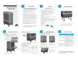
InstallationDetails
Mounting the Air Cooler
Handling and installing the cooler is always much easier if you
remove the pad frames first.
:
Use 24g or stronger metal roof jack. The cooler may then be
attached directly to the jack.
:
Roof Jack preferred size is 24g steel or stronger. The supplied
roof jack adaptor may be required to attach the cooler to the
existing roof jack.
It is recommended that a strip of foam or sealant is
applied to the upper flange on the roof jack before securing the
cooler to provide an airtight seal. Ensure that the top of the roof
jack is level, then check the lip of the pan for level when the
cooler is in position on the roof jack. (Fig. 5)
New installation, Roof Jacks
Replacement installation, Roof Jacks
NOTE!
Raising the Cooler to its final location.
HANDLE WITH CARE. DO NOT DROP.
! Take care when moving the cooler that nothing
is allowed to penetrate into the discharge opening (such as
the end of a ladder), as damage may occur to the internal
cooler components. If a ladder is used as a slide for the
cooler to be pulled onto a roof or platform, we strongly
recommend the cooler be turned upside-down first. Protect
the lid from scratching.
Down draft
For lifting or pulling the cooler, always apply the ropes around
the full cabinet or the blower housing and NEVER tie them to any
of the four corner posts.
After placing the cooler on the roof jack check that water
spreaders and other internal components are all securely in
place.
: Model EAD148 does not require a mounting frame
or adaptor as they are designed to fix directly into the 17¾" x
17¾" roof jack. Models EAD265 & EAD385 are supplied with a
metal roof-jack adaptor for 19¾" x 19¾" roof jacks. (Figs 6, 12)
WARNING
EAD265&EAD385ONLY
Theadaptormustbescrewedintotheaircooleroutletfirst.
Thenliftthecoolerassemblyontotheroofjack.(Fig.12)
Side Draft: All side draft coolers require a special frame to support the
cooler from below or from the wall. Ducts may be attached directly to
the air opening of the cooler. Fig. 8 shows the safe area for drilling and
screwing. Use a sealing compound to achieve air tight connection.
OptionalSupportLegs
CoolerOrientation
OptionalBreezairsupportlegsareavailablefromyourBreezair
supplier. TheyhavebeendesignedtoattachtoalldowndraftEA
modelsandmaybeusedwhenadditionalsupportisnecessary.
Betterairflowandlowerbackpressurewillresultfromcareful
orientationoftheblowerandhousingasshowninfig.9below:
SideDraftcoolersshouldbesecuredtotheirmountingframes(where
used)withtheratchetclipanchorstrapssupplied.(Fig.10).Donot
over-tightenthestrapsasyoumightdistortthepan.

WaterInstallation
A permanent water supply is required to be connected to the float valve
that is factory fitted inside the cooler. The float valve controls the water
level in the pan automatically. The water connection point for DOWN
draft coolers is located underneath the pan, where the ½" float valve
nipple protrudes . (Fig. 12)
ThewaterconnectionpointforSIDEdraftcoolersisinsidethecooler
directlyontothefloatvalve.Routethewatersupplypipeeitherthrough
aholeintheblankfrontpanelofthecooler,or,throughaholeinthe
pandrilledinanycorneradjacenttothecornerposts.
Installamanualwatershut-offvalvenearthepointofentryofthe
watersupplytothecooler.Inareassubjecttowinterfreezing
installadraindownfeature.DONOTFITSHUTOFFVALVES
DIRECTLY ONTOTHEFLOATVALVENIPPLE.
WARNINGS!
1)Flushforeignmatterfromwatersupplypipebeforefinal
connectiontoavoiddamagetothefloatvalve.
2) Alwaysensurethatthewatersupplypipedoesnotplace
sidewayspressureontothefloatvalvenippleasitisplastic.
Overflow&BleedOffFeature
A special “bleed-off"fittingissuppliedwiththecoolerorinthePower
Pack.Ithasa3-foldfunction:itactsasanoverflow,adrainanda
bleed-off.Ifthewaterlevelgetstoohightheexcesswateroverflows
intothefittingandawaytowaste.Iftheuserwantstodrainthepanhe
canliftthefittingoutofthedrainholeandthepanwaterwillrunaway
towaste.Thebleedfunctionmustalwaysbecommissioned,exceptin
areaswhereitisillegaltorunwatertowaste.
EA EvaporativeCooler
4
®
14
15
12
4
®
Thecontinuous
bleedingofasmall
amountofwaterto
drainforcesfreshwater
toenterthecoolerand
reducestherateat
whichsaltandscale
builduponthepads.
Thebleed-offfittingis
insertedintothelarge
holealreadyformedin
thepan.(Fig.13,20).
Screwthetanknut
firmlyunderthepanby
hand.
Thebleedratecanbe
variedaccordingto
localconditions.Withall
theplasticplugs
removedfromthetray,
minimumbleedwill
occur.
13
Insert plugs to increase the bleed rate to suit your salt build up
experience. See heading Operating Adjustments for further
details. In those areas where draining of bleed-off water is illegal,
the bleed must be disabled. Use the "bleed stop" shield supplied
with the cooler. (Fig. 13)
WARNING! In cases where bleed-off is not used the pads
will require frequent inspection and replacement. Failure to
do so may cause water to leak into the building or onto the
roof, which may enter electrical components creating an
electric shock or fire hazard. Where this condition is
allowed to exist, Seeley International (Americas) accepts no
responsibility for any damage or injury that might occur.
Make sure the fitting is located correctly in relation to the pads
and that the large O-ring is on before placing the fitting into the
hole in the pan. Secure with clips provided. (Fig. 14)
Thedrainadaptorallowstheattachmentofa¾"drainhoseto
runwatertoawastepoint. Attachittothebleedfitting
underneaththepanbyusingthedrainnut.(Fig.15)

ElectricalInstallation
ELECTRICAL INSTALLATION
WARNING
WARNING
!
!
The electrical installation must be carried out by a licensed
and qualified electrician.
Ensure that all electrical connections are tight.
When retro-fitting the cooler to an existing
installation always turn off the electrical power at the source of
the wiring. DO NOT TAKE RISKS! Turn off and tape over the
circuit breaker or remove the fuses and keep them with you until
the job is complete. Set cooler, isolator switch, wall switch,
motor and pump to "off". Be sure to tell other occupants of the
building what you are doing.
Check to be sure that the voltage rating of the cooler
matches your electrical system voltage.
Sub-circuit wiring must be rated at cooler rated amperes or
higher, and must be protected by a suitable fuse or circuit
breaker. Sub-circuit cables are to be double insulated all the way
into the cooler junction box.
Loose
connections will cause overheating that may lead to machine
damage or fire.
Replace all covers on completion of the work, using only the
screws supplied.
SEELEY INTERNATIONAL – INSTALLATIONMANUAL
5
WIRINGDIAGRAMS
WiringOption1
WiringOption2
Fig.18showsthefieldwiringfora2
speedcoolerWITHLINESUPPLY
WIREDFIRST TO THECOOLER(not
firsttothewallcontrol).
Fig.19showsthefieldwiringfora2
speedcoolerWITHLINESUPPLY
WIREDFIRST TO THEWALL
CONTROL (notfirsttothecooler).
FORINFORMATIONCONCERNING
OTHERWIRINGCONFIGURATIONS
CALL BREEZAIR TECHNICAL
DEPARTMENT.(800)926-6824
18
17
WiringOption1
WiringOption2
Do not tamper with factory wiring.
must set the motor full load amps
using a clip-on ammeter.
Before leaving the job, a trained,
licensed technician must check that
the cooler is operating correctly, and
Make this
adjustment at the motor pulley
(sheave). See later detail under
heading "Operating Adjustments".
Thejunctionboxisalreadyfactoryfittedtotheblowerhousing.
Attachedtothejunctionboxisamainpowersupplyterminationbox.
Themainpowerterminationboxismadeintwosectionstofacilitate
easywiringconnections.Knock-outsareprovidedfor½"conduit. A
holemustbedrilledfor¾"conduits.(Fig.17)
Thejunctionboxcontainsplugreceptaclesforfanmotor,waterpump,
andotheroptionalfeaturesifused.Fanmotoramperesmustbe
adjusted usingaclip-onammeter
onthepowerwires.
Connectthepowersupplyandcontrolcablesinsidethis
terminationboxasshownonwiringdiagram/sbelow.
Thejunctionboxisfactorysealed;donotattempttoopenit;
therearenofieldserviceablepartsinside.
beforeclosingtheterminationbox
16

P
o
l
e
a
h
a
c
i
a
f
u
e
r
a
P
o
l
e
a
h
a
c
i
a
a
d
e
n
t
r
o
ILL1208-B
C
A
B
D
E
Waterlevelshouldbe
about¾"belowthe
overflowoutlet(top
lipofbleed-offtray)
whenthevalveshuts
off.(Fig.20)
½"NPT (15NB)
19
6
®
NEVER ADJUST
THE WATER LEVEL
WITH THE COOLER
RUNNING because
the residual water in
the pads and pipes
will cause the water
to over flow when it
runs back into the
pan.
21
20
22
EA EvaporativeCooler
Operating Adjustments
Water level:
The water level in the cooler is important. Adjust the level at the float
valve inside the cooler. Rotate the large plastic float CCW or CW to
change the level. CW will lower the level; CCW will raise the level. (Fig.
19)
ILL579-E
Motor Power (Amps)
Important: Install all the pad frames except the one on the motor side.
Ensure that all intended doors, windows or other means of exhaust are
open in the building, and that all outlet grilles are open fully.
Set the cooler running at the highest speed for about 10 minutes, or
until the motor has reached its normal operating temperature (hot!).
Motorloadmustbechecked thepumprunning.
Thisshouldbedonebyatrainedlicensedelectrician.
motornameplateamps.
without
Clipyourammeterontothefreecableinthemainterminationbox.
(Fig21)
Checkthemeasuredampsagainstthe
If the measured amps are less than the nameplate amps the adjustable
motor pulley sheave must be altered to increase the blower speed,
thereby delivering the full capability of the cooler to your installation.
The measured amps must be equal or close to, but never
more than the nameplate amps.
Failure to do this will
cause overheating in the motor and may cause the motor’s
thermal protector to trip.
Pulley (Sheave) Adjustment
DO NOT USE THE PULLEY ADJUSTMENT TO SET BELT
TENSION.
Never
attempt this procedure with the cooler operating.
increase the fan speed
turn the
adjustable sheave clockwise.
(See heading "Pulley
(Sheave) Adjustment")
If the measured amps are greater than the motor nameplate
amps the fan MUST be slowed down by adjusting the motor
pulley sheave in the opposite manner.
Replace all covers when adjustments are completed using the
screws provided.
The motor pulley is adjustable in order to set the motor amperes
at the correct (nameplate) level, and thus provide the owner with
full machine cooling capacity.
The adjustment is made with the cooler switched OFF.
Remove the drive belt.
To (and therefore the motor amps), the
two halves of the pulley must be closer together, ie:
(Fig.22)
A =
B=Grubscrew.
C= Adjustable
Sheave.
D=
E=Lockingcap
securingscrew.
FixedSheave.
LockingCap.
To (andthereforethemotoramps),the
twohalvesofthepulleymustbefurtherapart,ie:
.(Fig.22)
Theouterhalfofthepulleyisonathreadandcanbemovedin
oroutbyremovingthelockingcapandthenturningtheouter
halfbyhandinthedesireddirection.
Whenanadjustmentismade,replacethelockingcap,aligning
thescrewholewiththenearestholeintheadjustablesheave.
Lockitintoplacewiththesecuringscrew.Refitthebelt,reset
thebelttension,thenrunthe
decreasethefanspeed
turnthe
adjustablesheavecounter-clockwise
coolerandchecktheamps.
Repeattheprocessuntiltheamplevelisset.Youcanstartand
stopthecoolerforthisprocedurebyusingtheisolatingswitch
insidethecooler.
Ifitistootighttherewillbe
excessivebeltandbearingwear.Ifitistooloosetherewillbe
beltslip,excessivebeltwearandlossofcoolerperformance.
Therearetwoadjustingboltswithlockingnutsalreadyfittedto
themotorcradle.
Thetensionshouldbeadjustedsothatthedeflectiononone
sideofthebeltis5/8"to13/16". Tomaketheadjustment,loosen
thelockingnutsandscrewtheboltsinoroutasrequiredto
changethebelttension.Re-tightenthelockingnuts.
BeltTension
Belttensionisimportant.

1
7
Maintenance
Instructions
Bleed Off
Salt deposit can NEVER be entirely
eliminated, only the rate of deposit
can be changed.
!
OPERATION OF COOLER
See previous heading "Overflow and
Bleed-Off feature" under "Water
Installation".
Adjusting the bleed rate is necessary to
reduce the salt deposit on the pads.
The bleed feature
causes some salt concentrated water in
the pan to be drained away. Fresh water
enters the cooler automatically as the
salty water exits.
The rate of bleed will vary according to
water quality, but should be set to a
minimum rate as set out below:-
EA148 (small cabinet): 0.05 gpm
Previous warning about running
coolers without bleed-off.
Evaporative air coolers always function
on 100% fresh outside air.
EA265 (med. cabinet): 0.08 gpm
EA385 (large cabinet): 0.13 gpm
Bleed adjustment cannot be
precise as operating conditions vary
continually.
NOTE!
NOTE
Using your Cooler
!
!
!
!
!
!
!
!
Replace the Bleed-off fitting. (This
should have been removed at the end of
last season. Refer. End Season
Maintenance).
Reconnect the water supply line and
turn on the water supply.
Check the float valve for correct
operation and check water level.
Inspect and clean the pump filter and
impellor housing.
(To remove pump from filter)
Press release button on filter, twist the
pump body with button depressed, lift
pump body out of filter base.
Check belt tension and adjust if
necessary.
The main blower shaft bearings are
sealed for life and do NOT require oiling
or greasing.
Turn on the cooler isolating switch.
Put the pad frames back on the cooler.
Restore main power supply and run
cooler according to the previous
instructions under "Operation of
Cooler".
!
!
!
!
!
!
!
!
In-season Maintenance
Turn off the power supply to the cooler.
Remove pad frames
Turn off the isolating switch inside the
cooler.
Inspect the pads and clean or replace
as required (see previous instructions
under "Pre-season Maintenance").
Check water level and adjust if
necessary.
Turn on the cooler isolating switch.
Put the pad frames back on the cooler.
Restore main power supply and run
cooler according to the previous
instructions under "Operation of
Cooler".
It is important to recheck the motor
amps again after re-setting the belt
tension. Correct belt tension ensures
the belt will not slip. Check the
temperature of the belt by hand after
each adjustment, by turning off the
cooler and holding one side of the
belt in your hand. If the belt is warm
to touch, it is slipping! Continue to
tighten until it runs cool. (fig. 24)
Therefore you must either open doors
and windows, or, provide exhaust
outlets in the building. FAILURE TO
PROVIDE ADEQUATE EXHAUST
OPENINGS WILL CAUSE A BUILD UP
OF HUMIDITY INSIDE THAT WILL
BECOME VERY UNCOMFORTABLE.
Turn on the water supply and make
sure the shut off valve at the cooler is
also on.
Turn on electrical power supply.
Wait a few minutes for the water to fill
the cooler pan.
Turn on "cooling" at the wall control to
start the pump and pre-wet the pads.
Turn on the fan to High or Low speed
as desired.
In humid weather you may feel more
comfortable by turning off the cooling to
run the fan only.
You can create your own pattern of air
flow in the building by adjusting the
outlet vents and doors and windows to
direct the air where you want it.
All maintenance must be done
by a trained, licensed technician.
Turn off the power supply to the cooler.
Remove pad frames
Turn off the isolating switch inside the
cooler.
Fit new pads if necessary.
If the pads are re-used they can be
easily cleaned by hosing them with
clean water, but do not use excess
pressure because you might create
holes in the pad media.
Start up
MAINTENANCE INSTRUCTIONS
!
The pads supplied have been
selected to give the highest possible
c ooli n g p erfo r m a n ce. W H E N
REPLACING PADS DO NOT USE
ALTERNATIVES. The manufacturer
i s n o t r e s p o n s i b l e f o r t h e
performance, damage to, or safety of
the air cooler when alternative pads
are used. Using poor quality or
incorrect pads may cause water
carry-over that might enter electrical
components creating an electric
shock or fire hazard.
!
!
!
!
!
!
!
!
!
!
!
Pre-season Maintenance
NOTE
Operating
Adjustments
24
SEELEY INTERNATIONAL – INSTALLATIONMANUAL
7

1
8
To remove bearings:
Disconnect electrical power to the
cooler.
Remove V-belt.
Remove black plastic end cap (if fitted)
from the end of the square shaft.
Remove small black plastic pin in
blower pulley (use screw driver as a
lever).
Remove two small, black, plastic pins
in the shaft on each side of the blower.
(use screw driver as lever).
Remove blower pulley. As you begin to
extract the pulley, depress the two
bearing mount clips together (located
inside the pulley boss) to allow the
pulley to slide off the shaft.
Remove the black, plastic bearing
locks covering the bearing hubs by
twisting them counter-clockwise. You
may need make a special tool for this
job. (Fig. 26).
!
!
!
!
!
!
!
!
!
Discard all the old components and
use the new ones in the bearing kit.
:
Fit new bearings to the two bearing
mounts.
To replace bearings
!
!
!
!
!
!
!
!
!
!
Fit new rubber resilient mounts over
the bearings.
Clean the shaft and apply a small
amount of lubricant to aid re-assembly.
Push the blower shaft through so it
protrudes through the non-drive end
hub.
Push the non-drive end bearing
assembly onto the shaft, lining up the
small hole on the mount with the hole in
the shaft. Insert the pin.
Gently drift the non-drive end
bearing/shaft assembly into the hub and
replace the bearing lock by twisting
clockwise.
Push the drive end bearing assembly
along the shaft and into the hub. This
may require gentle assistance with
hammer and drift.
Engage drive end bearing lock into its
housing and twist clockwise to lock.
Replace the two small pins each side of
the blower on the shaft.
Push the blower pulley back onto the
shaft making sure the small hole in the
pulley lines up with the corresponding
hole in the shaft. Insert small black pin.
Push black plastic end-cap into end of
shaft.
NOTE! The bearing mount is different
for drive end and non-drive end of
shaft.
End-season Maintenance
!
!
!
!
!
!
!
!
!
!
Turn off the power supply to the cooler.
Remove pad frames
Turn off the isolating switch inside the
cooler.
Remove pad frames. Clean them by
hosing them with clean water, but do not
use excess pressure because you
might create holes in the pad media.
Remove and clean the special water
"spreader" plates located under each
edge of the top panel. Do not disconnect
from water hose. When replacing them,
check underneath to see that the
spreaders are correctly located in the
notches under the top panel.
Drain all the water form the cooler by
removing the bleed tray. Do NOT put it
back until next season. Do not lose the
O-ring seal.
Disconnect the water supply pipe from
the pan. Make sure no water is left in the
float valve. Leave pipe disconnected
and drained for winter to prevent
freezing and splitting.
Clean the bottom pan thoroughly.
Replace pads frames.
Cover the cooler for winter if desired.
Bearing Replacement
Sometimes a blower shaft bearing will
fail and must be replaced in the field.
Before removal of the failed bearing/s
obtain a Bearing Kit, part no. 800523.
(Fig. 25)
! Place a strong, flat screwdriver across
the corner of the non-drive end bearing
mount (still on the shaft) and hit it
sharply with a hammer to break the
mount. The bearing should then be
freed to slide off the shaft. (Fig. 27)
The blower shaft should then be able to
be pushed to push the drive end bearing
assembly out from the hub. In a similar
way, break the drive end bearing mount
to free the bearing.
MaintenanceInstructions
27
25
26
28
EA EvaporativeCooler
8
®

1
9
Troubleshooting
PROBLEM PROBABLECAUSE SUGGESTEDREMEDY
InadequateCooling
Under-sized cooler.
Replace with larger cooler.
Replace with larger ducts.
Under-sized ducts.
Clean or replace pads.
Clogged or dirty cooling pads.
Check water distribution system for
possible obstruction in hoses.
Check pump.
Dry pads or lack of water while
cooler is operating.
Make sure there is adequate
provision for exhausting stale air
from building (open windows and
doors).
Insufficient air discharge openings
or inadequate exhaust from
building, causing high humidity and
discomfort.
Remove backdraft damper and
substitute manual slide damper.
Excessive resistance from poorly
located backdraft damper.
On days during summer when
ambient humidity is high the cooler
will not reduce the temperature as
much as on drier days. There is no
remedy except to shut off the pump.
Excessive ambient humidity (see
also item above re inadequate
exhaust).
Check motor amps. If below motor
nameplate amps, re-adjust motor
pulley to increase fan speed.
Blower running too slow.
Rapid formation of white deposits
on pads and louvres.
Belt slipping.
Tighten belt by re-adjusting motor
position. Replace belt if worn.
Fanoutofbalanceduetodirt.etc.
Cleanthefan.
Noisycooler.
Air distribution system creating too
much back pressure, or changes of
direction too sudden, or grilles too
small.
Havecontractorre-evaluatehis
design;usebendsinsteadof
elbows;changegrillesizes.
Beltsquealing.
Tightenbelt.
Highmineralcontentofsupplywater.
Increase the bleed rate.
SEELEY INTERNATIONAL – INSTALLATIONMANUAL
9

1
10
Troubleshooting
PROBLEM PROBABLECAUSE SUGGESTEDREMEDY
Beltloose.
Tightenbelt.
Belt slipping or wearing excessively.
Pulleysoutofline.
Alignpulleys.
Wornbelt.
Replacebelt.
Wornorwarpedpulleys.
Replaceandre-alignpulleys.
Moistureonbelt.
Stopanywaterleaks.
Pumpcircuitbreakertripped.
Checkpumpforfaults.Replaceif
necessary.
Pumpfailstooperate.
Pumpmotorfailure.
Replacepump.
Looseelectricalterminations.
Checkallelectricalterminations.
Pumpcontrolswitchfaulty.
Replacecontrolswitch.
Motor circuit breaker tripped.
Check cause of overload, especially
motor amp setting. Adjust if
necessary to at or below motor
nameplate amps. Reset circuit
breaker.
Blower fails to start.
Incorrectwiringofpumpand
controlswitch.
Connecttheelectricalconnections
correctly.
Check cause of overload. Reset
circuit breaker or replace fuse.
Check all electrical terminations.
Replace control switch.
Replace motor.
Check and tighten pulley and belt.
Install new belt.
Consult with power supply authority.
Fit correct size motor.
Main power circuit breaker tripped
or fuse blown.
Loose electrical terminations.
Defective control switch.
Blower motor burned out.
Belt or pulley loose.
Belt broken.
Low system voltage.
Incorrect motor; motor changed but
wrong size fitted.
EA EvaporativeCooler
10
®

1
11
Troubleshooting
PROBLEM PROBABLECAUSE SUGGESTEDREMEDY
Floatvalveadjustmentnotcorrect.
Adjustfloatvalve.Ensuresupply
waterpipeisnotstrainingthevalve
sideways.
Continuousoverflowofwater.
Unpleasantodour.
Heavypaddeposits.
Cleanorreplacepads.
Loosewaterhoseconnections.
Tightenallconnections.
Waterbeingblownintothe
building.
Waterhosebroken.
Replaceanycrackedorbroken
hoses.
Covernotfittedonfloatvalve.
Installcorrectcoveronfloatvalve
topreventspray.
Padsnotfittedcorrectlyintopad
frames.
Makesurepadsproperlyinstalled.
Waterleveltoolow,causingpump
tocreatefountainthatisbeing
suckedintoairstream.
Increasewaterlevel.
Incorrectordamagedpadsfitted.
Replacewithmanufacturer's
recommendedpads.
Newcoolerpads.
Draintank,refill,runpumpfora
while.
Coolerlocatednearsourceof
unpleasantodour.
Removesourceofodouror
relocatecooler.
Algaeinpanwater.
Drainpan,cleanthoroughlywith
strongcleansingagent,refill,
changepads.
Padsremainwetaftershutdown.
Runfanon"vent"for10minutes
aftercoolingcycletodrypadsout.
Heavypaddeposits.
Cleanorreplacepads.
Insufficientwaterinpan.
Adjustfloatlevel.
Pump runs but no water circulation.
Pump runs but pads lack water.
Waterhosesblocked.
Checkandcleanoutblockage.
Unkinkhose.
Pumpfilterblocked.
Cleanpumpfilterandimpellor
housing..
SEELEY INTERNATIONAL – INSTALLATIONMANUAL
11

1
12
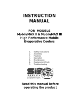
ExplodedViews&SpareParts
EXPLODEDVIEWS ANDREPLACEMENTPARTS
Whenorderingreplacementparts,pleasequoteitemnumberanddescription.
TYPE
Small
Medium
Large
DOWNDRAFT
EAD148
EAD265
EAD385
SIDEDRAFT
EAS148
EAS265
EAS385
DRIVEEND
38
40
42
39
17
18
21
23
22
28
9
33
34
41
37
35
13
32
33
8
31
30
32
36
ILL654-C
19
20
19A
BLOWERHOUSINGEXPLODEDDIAGRAM
29
V-BELTREPLACEMENT
Refertotableforappropriatebeltsizeinformation.
EAS148- A49(supplied),4L-510(alternate)
SIDEDRAFT DOWNDRAFT
Small EAD148- A49(supplied),4L-510(alternate)
EAS265- A50(supplied),4L-520(alternate) EAD265- A50(supplied),4L-520(alternate)
EAS385- A55(supplied),4L-570(alternate) EAD385- A54(supplied),4L-560(alternate)
Medium
Large
EA EvaporativeCooler
12
®

1
13
ExplodedViews
SEELEY INTERNATIONAL – INSTALLATIONMANUAL
13

1
14
ExplodedViews
EA EvaporativeCooler
14
®

1
15
Notes
SEELEY INTERNATIONAL – INSTALLATIONMANUAL
15

1
16
Installationchecklist
CUT ALONG LINE
Cooler level and secure.
All roof work properly sealed.
Ductwork and air distribution checked and outlets correctly set.
Signed by Installer: …………………………………………………
Dated: ………………………………………………………………
All wiring complete.
Control switch correctly installed.
Belt tension and alignment correctly adjusted.
Fan runs in correct direction at all speeds (clockwise when viewed
from pulley side).
Motor amps tested at high speed with vents and windows open.
Amps input to the motor recorded: high__________amps
low___________amps
Motor and pump correctly plugged into sockets.
Motor pulley adjusted and tight on shaft.
Drain/overflow fitting correctly installed.
Water level and float adjustment checked.
Pump runs and water evenly distributed to all cooling pads.
All control functions checked.
Owner instructed on correct operating procedure and supplied with
operating instructions.
SERVICEENQUIRIES:
ContactyourlocalDealerorInstaller
forassistance.
OwnersName:______________________
__________________________________
Telephone:_________________________
Address:___________________________
__________________________________
__________________________________
Dealer:____________________________
__________________________________
Installer:___________________________
__________________________________
DateInstalled:_______________________
ModelNo.:__________________________
SerialNo.:__________________________
Motor Type:_________________________
MotorHP:__________________________
EA EvaporativeCooler
16
®

1
17
SparePartsList
ITEM DESCRIPTION QTY
1 PAN(TANK) 1
2 LID 1
3 PANEL FRONT (forSidedraftandsmalldowndraft) 1
4 PADFRAME 3or4
5 PAD ASSEMBLY 3or4
6 WIRE ASSEMBLY (padretainer) 3or4
7 POST CORNER 4
8 SCROLL (blowerhousing)LH(motorside) 1
9 SCROLL (blowerhousing)RH 1
10 PLATE(cut-off) 1
11 BRIDGE 1
12 CONNECTOR(lidtoscroll)forsmalldowndraft 2
13 BAFFLE(anti-vortex) 2
14 COVERPLATE(smalldowndraftonly) 1
15 SEALING TAPE
16
17 PLATE(motormount) 1
18 BOLT ROUNDHEADCOACH 2
19 SPEEDNUT 5/16UNC (motormount) 2
19a BOLT 5/16HEX.(motormount) 2
20 NUT 5/16HEX. (adjusterbkts-2 &bolts-4) 6
21 BRACKET adjuster 2
22 BOLT 5/16adjusting 2
23 BOOT plastic,adjusterbolttip 2
24 RIVETS&WASHERS
25 PLUGforslotsindowndraftpan,blowermountupstand. 16
26 WASHER,NYLONfloatvalve 1
27 PUMP WATER 1
28 MOTORBLOWER 1
29 JUNCTIONBOX 1
30 BLOWERCENTRIFUGAL 1
31 SHAFT BLOWER 1
32 BEARINGBLOWER 2
33 MOUNT RESILIENT BEARING 2
34 MOUNT,BEARINGnon-driveend 1
35 MOUNT,BEARINGdriveend 1
36 LOCK,BEARINGnon-driveend 1
37 LOCK,BEARINGdriveend 1
38 PULLEY,BLOWER,8"OR9" 1
39 PULLEY,MOTOR-adjustable 1
40 PIN,plastic,black 3
41 CAP,ENDSHAFT 1
42 V-BELT 1
43 SPREADERwaterdistribution 3or4
44 4-WAY DISTRIBUTOR(water) 1
45 HOSE¾"ID,PVCwaterdistribution
46 HOSE½"ID,PVCwaterdistribution
47 BLEED-OFFFITTING 1
48 BLEEDSTOP usedonlywherebleedillegal 1
49 BLEED-OFF ADAPTOR 1
50 FLOAT VALVE, AUTO 1
51 BLEED-OFFLOCKING NUT 1
53 CAP usedtopluganyunuseddistributoroutlet 1
54 ADAPTOR,ROOFJACK(galv.steel) 1
56 TIEDOWN, ANCHOR&STRAP 4
SEELEY INTERNATIONAL – INSTALLATIONMANUAL
17

SeeleyInternational(Americas)
Phone:602-353-8066
Fax:602-353-8070
TollFree:1-800-926-6824
www.convaircooler.com
839165-E
seeleyinternational.com
US1112
ItisthepolicyofSeeleyInternationaltointroducecontinualproductimprovement.
Accordingly,specificationsaresubjecttochangewithoutnotice.
/