Page is loading ...

Subject to change without prior notice [email protected].hk
www.acs.com.hk
User Manual V1.02
ACR330 Validator
with QR Code Scanner

ACR330 Validator with QR Code Scanner – User Manual [email protected].hk
Version 1.02 www.acs.com.hk
Page 2 of 61
www.acs.com
.hk
Table of Contents
1.0. Introduction ............................................................................................................. 4
2.0. ACR330 Hardware Overview ................................................................................... 5
2.1. Parts of the Reader ................................................................................................................ 5
2.1.1. Connection Ports ........................................................................................................... 6
2.1.2. Input Power, RS232, RS485 Pin Assignment ............................................................... 7
2.1.3. SAM Slot Arrangement ................................................................................................. 8
2.1.4. LTE Board Description .................................................................................................. 9
2.2. ACR330 EVK Components.................................................................................................. 10
2.3. Installing the Back Mount ..................................................................................................... 11
2.3.1. Preparing the Components ......................................................................................... 11
2.3.2. Installing ACR330 using a Vertical Pole ..................................................................... 16
2.3.3. Installing the ACR330 using a Horizontal Pole ........................................................... 23
2.4. Turning the Device ON/OFF ................................................................................................ 30
2.4.1. Turning on the Device ................................................................................................. 30
2.4.2. Turning off the Device ................................................................................................. 30
2.5. Accessing the ACR330 through a PC using LAN ................................................................ 31
2.6. Replacing the Real Time Clock (RTC) Battery .................................................................... 34
3.0. ACR330 Software Overview .................................................................................. 36
3.1. C++ Software Block Diagram .............................................................................................. 36
3.2. Java Software Block Diagram.............................................................................................. 37
3.3. ACR330 Demo ..................................................................................................................... 38
3.3.1. Contactless Module..................................................................................................... 38
3.3.2. Connectivity Module .................................................................................................... 43
3.3.3. Barcode Module .......................................................................................................... 48
3.3.4. GPS Module ................................................................................................................ 50
3.3.5. Card Slot Module ........................................................................................................ 51
3.3.6. LED/Speaker Settings Module .................................................................................... 52
3.3.7. Settings Module .......................................................................................................... 54
3.3.8. Power OFF Module ..................................................................................................... 55
3.4. Installing an Application ....................................................................................................... 56
3.4.1. Method 1: Loading the Application via USB Thumb Drive .......................................... 56
3.4.2. Method 2: Loading the Application to the Device ....................................................... 57
3.5. Removing the Installed Application ..................................................................................... 59
3.6. Changing the Application Directory (For FW1.7.10 and below) .......................................... 60
3.7. Re-flashing the Device ......................................................................................................... 61
List of Figures
Figure 1 : ACR330 Parts ....................................................................................................................... 5
Figure 2 : ACR330 Connection Ports ..................................................................................................... 6
Figure 3 : ACR330 Input Power ............................................................................................................. 7
Figure 4 : SAM Slot Arrangement .......................................................................................................... 8
Figure 5 : LTE Board Components ........................................................................................................ 9
Figure 6 : ACR330 EVK Components .................................................................................................. 10
Figure 7 : Pole Hole Position ................................................................................................................ 11
Figure 8 : Power Button ........................................................................................................................ 30
Figure 9 : Jumper Location................................................................................................................... 31
Figure 10 : RSR232 Debug Console Cable ......................................................................................... 31
Figure 11 : Ethernet Port ...................................................................................................................... 32
Figure 12 : RJ11 Serial Port ................................................................................................................. 33
Figure 13 : C++ Software Block Diagram ............................................................................................. 36

ACR330 Validator with QR Code Scanner – User Manual [email protected].hk
Version 1.02 www.acs.com.hk
Page 3 of 61
www.acs.com
.hk
Figure 14 : Java Software Block Diagram ............................................................................................ 37
Figure 15 : ACR330 Demo Default Screen .......................................................................................... 38
Figure 16 : Contactless Module ........................................................................................................... 38
Figure 17 : DESfire TOP-UP ................................................................................................................ 39
Figure 18 : DESfire PAY ....................................................................................................................... 40
Figure 19 : DESfire CHECK BALANCE ............................................................................................... 41
Figure 20 : EMV Contactless Card ....................................................................................................... 42
Figure 21 : Connectivity Module ........................................................................................................... 43
Figure 22 : Connection and APN Settings ........................................................................................... 44
Figure 23 : NTP Settings ...................................................................................................................... 45
Figure 24 : Wi-Fi Settings ..................................................................................................................... 46
Figure 25 : Bluetooth Settings .............................................................................................................. 47
Figure 26 : Barcode / QR code Validity Check..................................................................................... 48
Figure 27 : Barcode / QR code Information ......................................................................................... 49
Figure 28 : GPS Settings ...................................................................................................................... 50
Figure 29 : Card Slot Information ......................................................................................................... 51
Figure 30 : LED Settings ...................................................................................................................... 52
Figure 31 : Speaker Settings ................................................................................................................ 53
Figure 32 : Device Information ............................................................................................................. 54
Figure 33 : Additional Settings ............................................................................................................. 54
Figure 34 : Auto Power Settings .......................................................................................................... 54
Figure 35 : Power OFF Module ............................................................................................................ 55
List of Tables
Table 1 : ACR330 Parts Description ....................................................................................................... 5
Table 2 : ACR330 Connection Ports Description ................................................................................... 6
Table 3 : ACR330 Input Power Pins Description .................................................................................... 7
Table 4 : ACR330 LTE Board Description .............................................................................................. 9
Table 5 : Rubber Adapter According to Pole Size and Orientation ...................................................... 14
Table 6 : Hole Cover According to Pole Size and Orientation.............................................................. 15

ACR330 Validator with QR Code Scanner – User Manual [email protected].hk
Version 1.02 www.acs.com.hk
Page 4 of 61
www.acs.com
.hk
1.0. Introduction
The ACR330 Bus Validator is designed specifically for Automatic
Fare Collection (AFC) systems. It offers the convenience of
cashless payment in buses, ferries, trams, railways and other
transportation modes.
The bus validator enables high-speed transaction processing and
records collection through 13.56 MHz contactless (RFID)
technology, supporting ISO 14443 Type A and B cards,
MIFARE®, and FeliCa. Being certified with major payment
standards such as PBOC Level 1 (Contactless) and EMV™
Levels 1 and 2 (Contactless) including MasterCard® Contactless
and Visa PayWave® offers flexibility to adapt to an open loop
payment system. An embedded barcode scanner enables
transactions through the use of print or mobile barcodes.
It has advanced wireless connectivity options for data transfer such as GSM/GPRS, 3G/4G, and Wi-Fi.
With an optional GPS feature, it can also be used to locate vehicles, manage fleets and set flexible
distance-based fares. Protecting the bus validator from harsh environment is its IP54 rating for dust
and water protection and the additional Military Standard MIL-STD-810 for shock and vibration.
This document provides detailed guidelines on using the ACR330.

ACR330 Validator with QR Code Scanner – User Manual [email protected].hk
Version 1.02 www.acs.com.hk
Page 5 of 61
www.acs.com
.hk
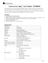
2.0. ACR330 Hardware Overview
2.1. Parts of the Reader
Figure 1: ACR330 Parts
Part Number
Part Name
1a, 1b, 1c,1d
Programmable Button with Backlight (Blue)
2
Blue LED Indicator (For passenger)
3
Yellow LED Indicator (For passenger)
4
Green LED Indicator (For passenger)
5
Red LED Indicator (For passenger)
6
LCD Display with Touch Panel
7
Tapping Area
8
1D/2D Barcode Scanning Area
9
Speaker
10
Green LED Indicator (For Driver)
11
Red LED Indicator (For Driver)
12
Buzzer
13
Power Button
14
SIM and SD Card Cover
15
Back Cover
Table 1: ACR330 Parts Description
1a
1b
1c
1d
2
3
4
5
6
7
8
9
10
11
12
13
14
15

ACR330 Validator with QR Code Scanner – User Manual [email protected].hk
Version 1.02 www.acs.com.hk
Page 6 of 61
www.acs.com
.hk
2.1.1. Connection Ports
Figure 2: ACR330 Connection Ports
Port Number
Port Name
1
Power Socket
2
RJ11 Serial Port (RS232, RS485)
3
USB Host
4
Ethernet
5
USB Client (for internal debugging)
6
Socket for External GPS Antenna
7
SAM Cover with 4 ISO7816 SAM Socket
inside
Table 2: ACR330 Connection Ports Description
1
2
3
4
5
6
7

ACR330 Validator with QR Code Scanner – User Manual [email protected].hk
Version 1.02 www.acs.com.hk
Page 7 of 61
www.acs.com
.hk
2.1.2. Input Power, RS232, RS485 Pin Assignment
Power Socket Type: Molex 43045-0400, Micro-Fit 3.0 Right Angle Header, 3.00mm Pitch, Dual Row,
4 Circuits
RS232, RS485 Socket type: RJ11
Pin Assignment is shown as below:
Figure 3: ACR330 Input Power
Pin Number
Pin Name
1
NC
2
RS232-TX
3
RS232-RX
4
RS485-A
5
RS485-B
6
GND
Table 3: ACR330 Input Power Pins Description
Note: Below is the application direct access device paths list:
RS232 - /dev/ttyO0 (115200 baud, 8 data bits, no parity, and 1 stop bit)
RS485 - /dev/ttyO1(115200 baud, 8 data bits, no parity, and 1 stop bit)
USB disk - /media/udiskp1

ACR330 Validator with QR Code Scanner – User Manual [email protected].hk
Version 1.02 www.acs.com.hk
Page 8 of 61
www.acs.com
.hk
2.1.3. SAM Slot Arrangement
The SAM Slot Arrangement is shown in the image below.
Figure 4: SAM Slot Arrangement

ACR330 Validator with QR Code Scanner – User Manual [email protected].hk
Version 1.02 www.acs.com.hk
Page 9 of 61
www.acs.com
.hk
2.1.4. LTE Board Description
Figure 5: LTE Board Components
Part Number
Part Name
1
4G Antenna Socket
2
GPS Socket
3
SD Card Slot
4
SIM Card Slot
5
Console Jumper Port (Console mode is
enabled through RS232 when jumper is
plugged in.
Speed: 115200 baud, 8 data bits, no parity,
and 1 stop bit)
Note: Jumper is not included in standard
product. May be purchased locally.
Table 4: ACR330 LTE Board Description
Note: Below is the application direct access device paths list:
MicroSD - /media/sdcardp1
4
5
1
2
3

ACR330 Validator with QR Code Scanner – User Manual [email protected].hk
Version 1.02 www.acs.com.hk
Page 10 of 61
www.acs.com
.hk
2.2. ACR330 EVK Components
Figure 6: ACR330 EVK Components
The ACR330 EVK contains the following items:
1. Debug Cable
2. Console Jumper Port
3. 1m DC Power Jack to Molex Power Cord
The cable should comply with the required power rating.
(example: 12V == 4A; 24V == 2A)
A DC jack adapter may be needed depending on the power supply used.
4. Demo Cards
Purpose: To be used for the demo pre-installed on the reader
2 pcs. Test Cards [Type: Mifare Desfire EV1]
There are QR Codes at the back of the cards to emulate both a valid and an expired
card.
Note: For more information about the demo, please check Section 3.3 - ACR330 Demo
1
2
3
4

ACR330 Validator with QR Code Scanner – User Manual [email protected].hk
Version 1.02 www.acs.com.hk
Page 11 of 61
www.acs.com
.hk
2.3. Installing the Back Mount
2.3.1. Preparing the Components
Prior to installation, it is necessary to ensure that the components are complete and in good condition.
Both the pole and the back-mount should be ready before the installation.
2.3.1.1. The Pole
To prepare the pole:
1. On the right side of the pole, check if the holes needed to secure the position of the ACR330 have
been well-drilled. For reference, please refer to the illustration below.
Note: The position of the holes can be adjusted depending on the requirement
Figure 7: Pole Hole Position
Cable out
2 Holes that
prevent the
back- mount
from moving
Cable in

ACR330 Validator with QR Code Scanner – User Manual [email protected].hk
Version 1.02 www.acs.com.hk
Page 12 of 61
www.acs.com
.hk
2. Check if the required cables (e.g. power cords) have been properly passed through the poles, and
that they can reach the position of the mounting with ample extra length.
3. Check the following details of the pole:
Diameter (31/32mm or 35mm)
Orientation (Vertical or Horizontal)
4. After checking the pole, proceed to check the back-mount.
2.3.1.2. The Back-mount
To prepare the back mount:
1. Unbox the tools. A back-mount, a key, and a brown box are included in the package.
Key
Back-mount
Brown Box

ACR330 Validator with QR Code Scanner – User Manual [email protected].hk
Version 1.02 www.acs.com.hk
Page 13 of 61
www.acs.com
.hk
2. Using the key, open the lock of the back-mount. The lock is located at the bottom part of the
back-mount as shown on the image below:
3. Unlocking the back-mount will cause it to disassemble into three parts: front cover, back
cover, and the water-resistant part. Rubber adapters are also included inside the back-
mount.
Front Cover
Back Cover
Water-resistant
Part
Rubber
Adapters

ACR330 Validator with QR Code Scanner – User Manual [email protected].hk
Version 1.02 www.acs.com.hk
Page 14 of 61
www.acs.com
.hk
4. Using the codes on their inner side, select the rubber adaptors that match the pole’s size
and orientation, as shown in the table below:
Orientation of pole
for mounting
Pole diameter
31/32mm
35mm
Horizontal (H)
HB-D31/32, HB-D31/32,
HT-D31/32, HT-D31/32,
HB-D35, HB-D35,
HT-D35, HT-D35,
Vertical (V)
VB-D31/32, VB-D31/32,
VT-D31/32, VT-D31/32,
VB-D35, VB-D35,
VT-D35, VT-D35,
Table 5: Rubber Adapter According to Pole Size and Orientation
5. Open the brown box. The following components should be inside the box:
For 31/32mm Pole
For 35mm Pole
Hole Cover
Screws
Rubber Part
Metal Part 1
Metal Part 2
Brown Box

ACR330 Validator with QR Code Scanner – User Manual [email protected].hk
Version 1.02 www.acs.com.hk
Page 15 of 61
www.acs.com
.hk
6. Select the appropriate hole cover according to the orientation of the pole, as shown in the
photo and in the table below:
Orientation of pole
for mounting
Pole diameter
31/32mm
35mm
Horizontal
VT, VT
VT, VT
Vertical
HT, HT
HT, HT
Table 6: Hole Cover According to Pole Size and Orientation
HT
HT
VT
VT
VT for
Horizontal Pole
HT for Vertical Pole

ACR330 Validator with QR Code Scanner – User Manual [email protected].hk
Version 1.02 www.acs.com.hk
Page 16 of 61
www.acs.com
.hk
2.3.2. Installing ACR330 using a Vertical Pole
Note: Please ensure that the components are well prepared before starting the installation.
To install the ACR330 using a vertical pole:
1. Place the rubber part on top of the metal part 1.
Note: This step is only applicable when using a 31/32mm pole. When using a 35mm pole,
please skip this step.
2. Put metal part 1 and metal part 2 on top of the pole and screw them together using PM4*20
screws (4 pieces). The order of screwing is shown on the picture below:
1
2
3
4

ACR330 Validator with QR Code Scanner – User Manual [email protected].hk
Version 1.02 www.acs.com.hk
Page 17 of 61
www.acs.com
.hk
Note: The gap between the two metal parts is around 3mm for any size (31/32/35mm) of
pole.), as shown in the picture below.
3. Screw the rubber adapters and hole covers using the PB2.0 screws (2 pieces). The exact
position is shown on the photos below:
Note: This is where the Connection
Cable (ie, Power Cord) will go
through. Make sure that the cables
are out so that they may be easily
connected to the ACR330 Validator
later on.
HT
HT

ACR330 Validator with QR Code Scanner – User Manual [email protected].hk
Version 1.02 www.acs.com.hk
Page 18 of 61
www.acs.com
.hk
For 31/32mm pole:
For 35mm pole:
HT
Hole Cover
HT
Hole Cover
HT
Hole Cover
HT
Hole Cover
VT-D31/32
Rubber Adapter
VT-D31/32
Rubber Adapter
VB-D31/32
Rubber Adapter
VB-D31/32
Rubber Adapter
VT-D35
Rubber Adapter
VT-D35
Rubber Adapter
VB-D35
Rubber Adapter
VB-D35
Rubber Adapter

ACR330 Validator with QR Code Scanner – User Manual [email protected].hk
Version 1.02 www.acs.com.hk
Page 19 of 61
www.acs.com
.hk
4. Screw the back cover to the metal parts using PM4*25 screws (4 pieces).
5. Place the O-ring on top of the metal part. The exact position is shown on the photo below:
O-ring
Note: This is where the
Connection Cable (ie, Power
Cord) will go through. Make
sure that the cables are out
so that they may be easily
connected to the ACR330
Validator later on.
Note: This is where the
Connection Cable (ie, Power
Cord) will go through. Make
sure that the cables are out
so that they may be easily
connected to the ACR330
Validator later on.

ACR330 Validator with QR Code Scanner – User Manual [email protected].hk
Version 1.02 www.acs.com.hk
Page 20 of 61
www.acs.com
.hk
6. Screw the water resistant part using PM3*8 screws (2 pieces).
7. Using the key, open the lock. The exact location is shown on the photo below:
Note: This is where the
Connection Cable (ie, Power
Cord) will go through. Make
sure that the cables are out
so that they may be easily
connected to the ACR330
Validator later on.
/