
H3C WA530X Access Point
Installation Guide
New H3C Technologies Co., Ltd.
http://www.h3c.com
Document version:6W101-20190527

Copyright © 2018-2019, New H3C Technologies Co., Ltd. and its licensors
All rights reserved
No part of this manual may be reproduced or transmitted in any form or by any means without prior written
consent of New H3C Technologies Co., Ltd.
Trademarks
Except for the trademarks of New H3C Technologies Co., Ltd., any trademarks that may be mentioned in this
document are the property of their respective owners.
Notice
The information in this document is subject to change without notice. All contents in this document, including
statements, information, and recommendations, are believed to be accurate, but they are presented without
warranty of any kind, express or implied. H3C shall not be liable for technical or editorial errors or omissions
contained herein.
Environmental protection
This product has been designed to comply with the environmental protection requirements. The storage, use,
and disposal of this product must meet the applicable national laws and regulations.

Preface
This installation guide describes the installation procedure for the H3C WA530X Access Point .
This preface includes the following topics about the documentation:
• Audience.
• Conventions.
• Documentation feedback.
Audience
This documentation is intended for:
• Network planners.
• Field technical support and servicing engineers.
• Network administrators working with the WA530X.
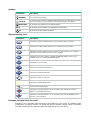
Conventions
The following information describes the conventions used in the documentation.
Command conventions
Convention Description
Boldface Bold
text represents commands and keywords that you enter literally as shown.
Italic
Italic text represents arguments that you replace with actual values.
[ ] Square brackets enclose syntax choices (keywords or arguments) that are optional.
{ x | y | ... }
Braces enclose a set of required syntax choices separated by vertical bars, from which
you select one.
[ x | y | ... ]
Square brackets enclose a set of optional syntax choices separated by vertical bars,
from which you select one or none.
{ x | y | ... } *
Asterisk marked braces enclose a set of required syntax choices separated by vertical
bars, from which you select a minimum of one.
[ x | y | ... ] *
Asterisk marked square brackets enclose optional syntax choices separated by vertical
bars, from which you select one choice, multiple choices, or none.
&<1-n>
The argument or keyword and argument combination before the ampersand (&) sign
can be entered 1 to n times.
# A line that starts with a pound (#) sign is comments.
GUI conventions
Convention Description
Boldface
Window names, button names, field names, and menu items are in Boldface. For
example, the
New User
window opens; click
OK
.
>
Multi-level menus are separated by angle brackets. For example,
File
>
Create
>
Folder
.

Symbols
Convention Description
WARNING!
An alert that calls attention to important information that if not understood or followed
can result in personal injury.
CAUTION:
An alert that calls attention to important information that if not understood or followed
can result in data loss, data corruption, or damage to hardware or software.
IMPORTANT:
An alert that calls attention to essential information.
NOTE:
An alert that contains additional or supplementary information.
TIP:
An alert that provides helpful information.
Network topology icons
Convention Description
Represents a generic network device, such as a router, switch, or firewall.
Represents a routing-capable device, such as a router or Layer 3 switch.
Represents a generic switch, such as a Layer 2 or Layer 3 switch, or a router that
supports Layer 2 forwarding and other Layer 2 features.
Represents an access controller, a unified wired-WLAN module, or the access
controller engine on a unified wired-WLAN switch.
Represents an access point.
Represents a wireless terminator unit.
Represents a wireless terminator.
Represents a mesh access point.
Represents omnidirectional signals.
Represents directional signals.
Represents a security product, such as a firewall, UTM, multiservice security
gateway, or load balancing device.
Represents a security module, such as a firewall, load balancing, NetStream, SSL
VPN, IPS, or ACG module.
Examples provided in this document
Examples in this document might use devices that differ from your device in hardware model,
configuration, or software version. It is normal that the port numbers, sample output, screenshots,
and other information in the examples differ from what you have on your device.
T
T
T
T

Documentation feedback
You can e-mail your comments about product documentation to [email protected].
We appreciate your comments.

1
Contents
Preparing for installation ···································································· 1
Examining the installation site ······································································································· 1
Installation site selection ······································································································· 1
Temperature and humidity requirements ·················································································· 1
Power supply ······················································································································ 1
Grounding and lightning protection ·························································································· 1
Installation accessories ··············································································································· 3
Installation tools and equipment ···································································································· 3
Installing the AP ··············································································· 5
Pre-installation tasks··················································································································· 5
Installation flowchart ··················································································································· 6
Connecting the grounding cable ···································································································· 6
Connecting Ethernet cables ········································································································· 7
Installing the AP ························································································································ 8
Attaching the AP bracket to the AP·························································································· 8
Pole-mounting the AP ·········································································································· 9
Wall-mounting the AP ········································································································· 11
Positioning the AP ···················································································································· 13
Connecting the AP to a PoE injector and the network ······································································ 13
Labeling cables ······················································································································· 15
Verifying the installation ············································································································· 15
Powering on the AP ·················································································································· 16
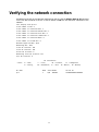
Verifying the network connection ······················································· 17
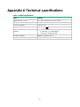
Appendix A Technical specifications ··················································· 18
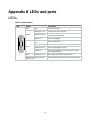
Appendix B LEDs and ports ······························································ 19
LEDs ····································································································································· 19
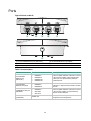
Ports ····································································································································· 20
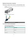
Optional transceiver modules ····································································································· 21
Transceiver module, fiber connector, and optical fiber views ······················································· 21
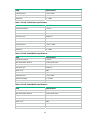
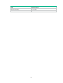
Transceiver module specifications························································································· 21
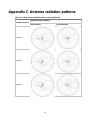
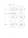
Appendix C Antenna radiation patterns ··············································· 24

1
Preparing for installation
WARNING!
Install the AP under the guidance of technical engineers and read this chapter before installation.
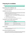
Examining the installation site
The AP is used for outdoor installation. Before installation, examine the installation site to ensure that
the AP will work in a good environment.
Installation site selection
The installation site must be selected according to the network planning and technical requirements
of telecommunications equipment, with factors such as climate, hydrology, geology, earthquake,
electric power, and transportation taken into consideration.
The location for installing the AP must meet the following requirements:
• Not exposed to high temperature, dust, harmful gases, electromagnetic interference sources
(high powe radars, radio stations, or electrical substations), unstable voltage, heavy vibration,
and loud noise.
• Dry, without any leakage, dripping, or dew.
• Away from inflammable and explosive substances.
• More than 5 m (16.40 ft) away from 3G and 4G base stations and antennas.
Temperature and humidity requirements
Table 1 Temperature and humidity requirements
Item Specification
Operating temperature
–30°C to +55°C (–22°F to +131°F)
Storage temperature
–40°C to +85°C (–40°F to +185°F)
Operating humidity
0% RH to 100% RH, non-condensing
Storage humidity 0% RH to 100% RH, non-condensing
Power supply
The AP uses a power injector for power input. No power injector is provided with the AP. You can
order an H3C PoE power injector to power the AP. See "Connecting the AP to a PoE injector and the
netwo
rk" for the connection method.
Grounding and lightning protection
The AP must be reliably grounded. Make sure the grounding points of the grounding conductor of the
AP, lightning arrestors, PE wire of the power cord, and antenna support are separate from each other,
make good contact, and are securely connected and treated with corrosion protection.

2
Ground resistance
• The ground resistance is usually required to be less than 5 ohms, and less than 10 ohms in an
area with less than 20 thunderstorm days a year. If a piece of angle steel is buried as the
grounding conductor, the ground resistance is required to be less than 10 ohms. In an area with
a higher ground resistance, reduce the ground resistance by using brine or resistance reducing
agent around the grounding conductor.
• The top of the grounding conductor must be a minimum of 0.7 m (2.30 ft) away from the ground
surface. In cold areas, the grounding conductor must be buried below the frozen soil layer.
Grounding conductor
• If a grounding strip is available, connect the yellow and green grounding cable of the AP to the
grounding strip. To make a grounding cable, make sure the cable has a cross-section area of a
minimum of 6 mm
2
(0.01 in
2
) and a length of no longer than 3 m (9.84 ft).
• If no grounding strip is available, bury a piece of angle steel/steel tube a minimum of 0.5 m (1.64
ft) long in the earth to act as the grounding conductor. It must be zinc-plated.
{ In the case of a piece of angle steel, the size must be a minimum of 50 × 50 × 5 mm (1.97. ×
1.97 × 0.20 in).
{ In the case of a piece of steel tube, it must have a wall thickness of a minimum of 3.5 mm
(0.14 in). Weld the yellow and green grounding cable of the AP onto the grounding
conductor and use anti-erosion treatment on the welding joint. With a cross-section area of
a minimum of 6 mm
2
(0.01 in
2
), the grounding cable must be as short as possible and must
not be coiled.
• Make sure the grounding terminals of all the lightning arresters of the AP and the peer device of
the AP are reliably grounded.
Ground lead
A ground lead is a metal conductor connecting a grounding net and a grounding strip. The grounding
cable of the AP must be connected to the grounding strip. The ground lead must be 30 m (98.43 ft) or
shorter. A piece of zinc-coated flat steel with a cross-section area of 40 × 4 mm (1.57 × 0.16 in) or 50
× 5 mm (1.97 × 0.20 in) is recommended. Connect the grounding strip and the ground lead of the AP
through the yellow and green grounding cable with an area of 35 mm
2
(0.05 in
2
), or weld them directly.
Use anti-erosion treatment on the welding joint.
Power grounding (AC)
• Use a power cord with a protective earth (PE). Do not use a power cord with only an L line and
an N line.
• The neutral line of the power cord must not be connected with the PGND of other
communications equipment. The L and N lines cannot be connected.
Lightning rod
• The lightning protection grounding (for example, the grounding of the lightning rod) must be
connected to the grounding conductor of the equipment room.
• The lightning rod must be tall enough to protect the AP and its antennas.
• In plain areas, the shielding angle of the lightning rod must be less than 45 degrees. In
mountainous areas or lightning areas, the shielding angle must be less than 30 degrees.
Ethernet cable
• Use a shielded twisted pair cable for outdoor installation. Make sure the devices at the two ends
of the cable are reliably grounded.
• If a metal tube is used, make sure the Ethernet cable is reliably grounded at both ends of the
tube.

3
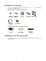
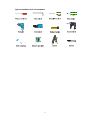
Installation accessories
Figure 1 lists the installation accessories provided with the AP. Figure 2 lists the installation
accessories to be prepared by users.
Figure 1 Installation accessories provided with the AP
Figure 2 Installation accessories to be prepared by users
Installation tools and equipment
When installing the AP, you might need the following tools. Prepare these tools and equipment
yourself as required.

4
Figure 3 Installation tools and equipment

5
Installing the AP
IMPORTANT:
To ensure radio coverage, have the AP installed by technical personnel as a best practice.
When you install the AP, follow these restrictions and guidelines:
• The AP is large and heavy. Avoid bodily injury and device damage during the installation.
• If you install the AP on a pole, make sure the pole is vertical to the ground and iron components
have been treated with corrosion protection.
• If you pole-mount the AP on the top of a building, make sure the AP does not project beyond the
sides of the building.
• To avoid high temperature caused by exposure to the sun, install the AP in a place without or
with less direct sunlight and take protection measures if necessary.
Pre-installation tasks
Before installing an AP, perform the following tasks:
• Connect the AP to the power source and the network. Examine the LED to verify that the AP
can operate correctly. For more information about the AP LED, see "Appendix B LEDs and
ports."
• Verify that cabling at the installation site has been completed.
• Record the AP MAC address and serial number marked on the rear of the AP for future use.

6
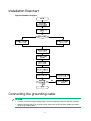
Installation flowchart
Figure 4 Installation flowchart
Connecting the grounding cable
CAUTION:
• Correctly connecting the grounding cable is crucial to lightning protection and EMI protection.
• Before connecting the AP to a power injector, make sure the AP has been reliably grounded
using the grounding cable.

7
The AP is not provided with a grounding cable. Prepare one yourself.
To connect the grounding cable to the AP:
1. Attach the ring terminal to the grounding cable.
Figure 5 Attaching the ring terminal to the grounding cable
2. Attach the ring terminal of the grounding cable to the grounding screw on the AP. Connect the
other end of the grounding cable to the earth.
Figure 6 Attaching the grounding cable to the AP
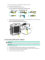
Connecting Ethernet cables
IMPORTANT:
Only CAT5e and above Ethernet cables can be used. As a best practice, use shielded twisted pair
(STP) cables.
To connect an Ethernet cable:
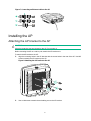
1. Disassemble the liquid-tight adapter and detach the rubber split sealing washer.
2. Feed the Ethernet cable through the liquid-tight adapter and attach the split sealing washer.
3. Connect the Ethernet cable to the target port on the AP.
4. Fasten the liquid-tight adapter and sealing nut.

8
Figure 7 Connecting an Ethernet cable to the AP
Installing the AP
Attaching the AP bracket to the AP
CAUTION:
Keep the protective vent port closed on the AP. Do not open it.
Before mounting the AP on a wall or pole, attach the AP bracket to it.
To attach the AP bracket to the AP:
1. Align the mounting holes in the AP bracket with the screw holes in the rear of the AP. Use M5
screws to attach the AP bracket to the AP.
Figure 8 Attaching the AP bracket to the AP
2. Use an M6 screw to attach the articulating arm to the AP bracket.

9
Figure 9 Attaching the articulating arm to the AP bracket
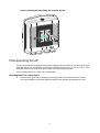
Pole-mounting the AP
Worm-gear clamps and a wall/pole bracket are required to pole-mount the AP. The worm-gear clamp
provided with the AP is applicable to poles with a diameter of 65 to 90 mm (2.56 to 3.54 in). If the
diameter of the pole is not in the range, prepare worm-gear clamps yourself.
You can mount the AP on a vertical or horizontal pole.
Mounting the AP on a vertical pole
1. Pass the worm-gear clamps through the mounting holes in the wall/pole bracket. Use the
worm-gear clamps to secure the wall/pole bracket to the vertical pole and fasten the nuts.

10
Figure 10 Securing the wall/pole bracket to the pole
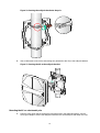
2. Use an M6 screw to secure the articulating arm (attached to the AP) to the wall/pole bracket.
Figure 11 Securing the AP to the wall/pole bracket
Mounting the AP on a horizontal pole
1. Pass the worm-gear clamps through the mounting holes in the wall/pole bracket. Use the
worm-gear clamps to secure the wall/pole bracket to the horizontal pole and fasten the nuts.

11
Figure 12 Securing the wall/pole bracket to the pole
2. Use an M6 screw to secure the articulating arm (attached to the AP) to the wall/pole bracket.
Figure 13 Securing the AP to the wall/pole bracket
Wall-mounting the AP
No expansion bolts are provided with the AP. Prepare them yourself.
To wall-mount the AP:
1. Use the AP bracket as a template to mark installation hole locations on the wall.

12
Figure 14 Marking installation hole locations on the wall
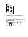
2. Drill holes with a diameter of 8 mm (0.32 in) at the marked locations, as shown in Figure 15.
When you drill holes, follow these restrictions and guidelines:
{ Hold the drill handle with both hands, with the bit vertical to the wall surface, and prevent
wall damage or tilted holes.
{ If the wall surface is too solid and slippery to locate the bit, punch a notch first.
{ Each hole must have the same depth.
3. Hammer expansion bolts into the holes and remove the nut and washers from each bolt. Do not
hammer the expansion bolts all the way into the wall and leave some space for hanging the AP.
Figure 15 Installing expansion bolts
4. Hang the AP on the expansion holes and fasten the screws to secure the wall/pole bracket to
the wall, as shown in Figure 16.
5. Use an M6 screw to
secure the articulating arm (attached to the AP) to the wall/pole bracket.
1
5
0
m
m
(
5
.
9
1
i
n
)

13
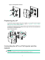
Figure 16 Securing the AP to the wall
Positioning the AP
The WA530X uses built-in antennas. After the AP installation, you can position the AP as required
based on the antenna radiation patterns as shown in "Appendix C Antenna radiation
patternsAppendix C Antenna radiation patterns"
T
o adjust the AP to the desired elevation angle, loosen the screw that attaches the articulating arm to
the AP bracket. To adjust the AP to the desired azimuth angle, loosen the screw that attaches the
articulating arm to the wall/pole bracket.
Figure 17 Adjusting the AP
Connecting the AP to a PoE injector and the
network
CAUTION:
Make sure the installation of the AP is complete before powering on the AP.

14
CAUTION:
• Place the PoE injector stable indoors in a well ventilated location.
• If multiple PoE injectors are installed in one equipment room or maintenance hole, use one
power strip for all these injectors and lead in the power strip from the air switch of the AC power
distribution box.
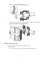
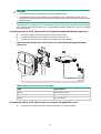
The PoE1 port on the dual-port H3C PoE injector must be connected to the uplink network through
the LAN1 port, and PoE2 through LAN2. The following procedures use the PoE1 port as an example
to connect the AP.
Connecting the AP to a PoE injector and to the network through the Ethernet copper port
1. Connect the power cord of the injector to an AC power source.
2. Connect the PoE1 port on the injector to the GE1 port on the AP.
3. Connect the LAN1 port on the injector to a switch or access controller.
Figure 18 Connecting the AP to a PoE injector and to the network through the Ethernet
copper port
Table 2 Dual-port H3C PoE injector description
Item Specifications
Model ADP060-55V-PoE-GL
Input 100 V – 240 V @ 1.5 A
Output 55 V @ 1100 mA
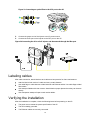
Connecting the AP to a PoE injector and to the network through the fiber port
1. Connect the SFP port on the AP to an Ethernet switch or access controller.
LAN1
PoE1
GE1
Page is loading ...
Page is loading ...
Page is loading ...
Page is loading ...
Page is loading ...
Page is loading ...
Page is loading ...
Page is loading ...
Page is loading ...
Page is loading ...
Page is loading ...
-
 1
1
-
 2
2
-
 3
3
-
 4
4
-
 5
5
-
 6
6
-
 7
7
-
 8
8
-
 9
9
-
 10
10
-
 11
11
-
 12
12
-
 13
13
-
 14
14
-
 15
15
-
 16
16
-
 17
17
-
 18
18
-
 19
19
-
 20
20
-
 21
21
-
 22
22
-
 23
23
-
 24
24
-
 25
25
-
 26
26
-
 27
27
-
 28
28
-
 29
29
-
 30
30
-
 31
31


H3C WA530X Installation guide
- Type
- Installation guide
- This manual is also suitable for
Ask a question and I''ll find the answer in the document
Finding information in a document is now easier with AI
Related papers
-
H3C WA536 Installation guide
-
-
-
-
-
-
-
-
-
Other documents
-
 Fastcabling 6100-58 User manual
-
 Hey! Play! M350042 Operating instructions
-
Dahua AWA6220-C Installation guide
-
-
-
A2 Software Owner's manual
-
Comnet CNGE28FX4TX24MSPOE2/48 User manual
-
Cisco Aironet 1570 Series Installation guide
-
 Wavion WBS-2400 SCT 120 Installation guide
-
CAME XNS08P Installation guide


