Page is loading ...

Owner’s Guide
Guide du propriétaire
Guía para el usuario
TH114-AF-GA / TH114-AF-GB
Non-programmable thermostat
Thermostat non programmable
Termostato no programable
33-00226EFS-06
M39044

Need Help?
For assistance with this product please visit https://www.resideo.com
Besoin d’aide?
Pour obtenir de l’aide, visitez https://www.resideo.com
¿Asistencia?
Para obtener ayuda sobre este producto, visite https://www.resideo.com

TH114-AF-GA / TH114-AF-GB
1
ENGLISH
Overview & operation
Before you start...........................................................................................................................................2
About your thermostat.................................................................................................................................3
Controls and display....................................................................................................................................4
Installation
Installing the thermostat..............................................................................................................................6
Wiring diagrams ..........................................................................................................................................7
Connecting the floor temperature sensor / remote control system .............................................................8
Setting the configuration switches...............................................................................................................9
Appendix
Floor temperature limits ............................................................................................................................10
Unoccupied Mode .....................................................................................................................................11
Ground fault protection (GFCI)..................................................................................................................12
Error messages.........................................................................................................................................14
Technical specifications.............................................................................................................................15
Warranty....................................................................................................................................................16
Table of contents

Owner’s Guide
2
ENGLISH
Read the entire document
CAUTION:
• Installation must be carried out by a certified electrician and must comply with national and
local electrical codes.
• Use this thermostat for resistive loads only.
• Do NOT install the thermostat in an area where it can be exposed to water or rain.
• To prevent severe shock or electrocution, always turn the power OFF at the service panel
before working with wiring.
• Install the thermostat onto an electrical box.
• Use special CO/ALR solderless connectors if you connect the thermostat to aluminum wires.
• Keep the thermostat's top and bottom air vents (openings) clean and unobstructed at all
times.
Before you start

TH114-AF-GA / TH114-AF-GB
3
ENGLISH
The TH114 non-programmable thermostat has three temperature control modes:
See page 9 on how to change the temperature control mode setting.
Supplied Parts
• One (1) thermostat
• Two (2) mounting screws
• Four (4) solderless connectors for copper wires
• One (1) floor sensor
• One (1) flat-tip screwdriver
About your thermostat
A mode: controls the ambient air temperature
F mode: controls the floor temperature using an external temperature sensor
AF mode: controls the ambient air temperature
maintains the floor temperature within desired limits using an external temperature
sensor

Owner’s Guide
4
ENGLISH
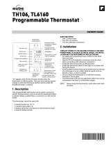
Controls and display
M39043
Backlight button (see page 5)
Temperature adjustment button
On/Off switch (see page 5)
Heating indicator. The number
of flames indicates the heating
intensity. The image disappears
when heating stops.
Temperature (see page 5)
GFI appears when the ground
fault protection is triggered
(see page 12)
Unoccupied Mode indicator
(see page 11)
TEST light/button for ground
fault protection (see page 12)
Appears when the set
temperature is displayed

TH114-AF-GA / TH114-AF-GB
5
ENGLISH
Temperature Display and Setting
The thermostat usually displays the room temperature. To view the set (desired)
temperature, press either of the buttons once. The set temperature is displayed for 5
seconds.
To set a new temperature, press one of the buttons repeatedly until the desired
temperature is displayed. To scroll faster, press and hold the button.
Backlight
The display illuminates for 5 seconds when the backlight button is pressed.
When either of the buttons is pressed, the display illuminates for 10 seconds. The set-
point temperature appears for the first 5 seconds, then the current temperature is displayed.
On/Off Switch
You can set the thermostat to OFF to cut power to the heating system when it is not in use
(e.g. in summer). The thermostat screen becomes blank but the settings are saved.

Owner’s Guide
6
ENGLISH
Turn the heating system off at the main electrical panel.
Loosen the bottom screw and remove the thermostat faceplate from
its wallplate. (The screw cannot be completely removed.)
Connect the thermostat to the load and to the power supply (see
page 7).
If the thermostat will be used in F or AF mode (see page 9), connect
the floor sensor (see page 8).
If you wish to connect a remote control device, see page 8.
Install the wallplate to the electrical box using the provided screws.
Set the configuration switches on the back of the faceplate (see page
9).
Install the faceplate back on the wall plate and tighten the screw. If
there is a sticker on the screen, peel it off.
Apply power to the heating system at the main electrical panel.
Test the ground fault protection (see page 12).
Installing the thermostat
M39045
Wallplate
Faceplate

TH114-AF-GA / TH114-AF-GB
7
ENGLISH
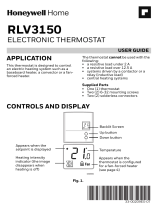
NOTE: Connect the wires using the provided solderless connectors for copper wires.
Wiring diagrams
M39036
L1(L)
L2(N)
M39035
L1(L)
L2(N)
120 V
Load
Power
supply
Black
Red
Red
Black
Black
Red
Red
Black
240 V Power
supply
Load
Black
Red
White
Black
Red
White
Black
Black Black

Owner’s Guide
8
ENGLISH
Insert the floor sensor wires through one of the two
openings on the wallplate and connect them to
terminals 1 and 2 (no polarity).
• The sensor wires must not come in contact with the
electrical wires and must be routed outside the
electrical box and follow the wall down to the floor.
• Position the sensor cable such that it does not
come in contact with the floor heating wires. The
sensor must be centered between two floor heating
wires for best temperature control.
• Do NOT staple the sensor head (the plastic end) to
the floor. Doing so might damage the sensor. Any
damage might not be noticeable during testing but
can become apparent several days later.
If you wish to connect a remote control device (see
page 11), insert the wires (use 18- to 22-gauge flexible
wires) through one of the two openings on the wallplate
and connect them to terminals 2 and 3 (no polarity).
Connecting the floor temperature sensor / remote control system
M39037
TEST
Floor
temperature
sensor
Remote control device

TH114-AF-GA / TH114-AF-GB
9
ENGLISH
Configuration switches are on the back of the faceplate. Factory settings are inside grey cells.
* See page 3 for definition of each mode.
- To select the F Mode, connect the floor temperature
sensor (see page 8) and place the switch in the F position.
- To select the AF Mode, proceed as follows: Connect the floor temperature sensor (see page 8).
Place the switch in the F position. If the thermostat displays Er, the sensor is improperly connected or
damaged. If the thermostat displays a temperature reading, place the switch in the AF position.
- To select the A Mode, place the switch in the AF position but do NOT connect the floor temperature
sensor.
Setting the configuration switches
# Configurations Up Down
S1 Displayed temperature unit °F °C
S2 Temperature control mode * FAF
M39018

Owner’s Guide
10
ENGLISH
The minimum and maximum floor temperature limits are available only if the temperature control mode is AF (see page 9).
If the floor temperature drops below the minimum limit or rises above the maximum limit, the thermostat will turn heating On
or Off respectively, regardless of the ambient temperature, to maintain the floor temperature within the set limits.
NOTE: The desired ambient temperature might not be attainable if the maximum floor temperature is set too low.
The minimum and maximum floor temperature limits are factory-set at 10 °C (50 °F) and 28 °C (82 °F) respectively. To
modify the limits, proceed as follows:
WARNING: To avoid damaging your floor, follow your floor supplier’s recommendations regarding floor temperature limits.
Switch the thermostat to Off.
While pressing either button, switch the thermostat back to On to access the floor tem-
perature limit settings.
Press the Backlight button briefly to switch between minimum and maximum floor temperature
settings.
Press the buttons to set the desired limit.
Press the Backlight button for 3 seconds to save your modifications. After the data are saved,
the thermostat displays the current temperature or “– –”.
NOTE: Your modifications are automatically saved if no button is pressed for 60 seconds.
Floor temperature limits (AF mode only)
M39019
M39020

TH114-AF-GA / TH114-AF-GB
11
ENGLISH
The Unoccupied Mode can be activated if you have connected the thermostat to a
remote control device equipped with a dry contact (see page 8). When the contact
closes, the Unoccupied Mode is activated and appears on the screen. In this
mode, the thermostat lowers its setpoint by 3.5 °C (7 °F) and all temperature
adjustments are blocked except for temporary bypass.
Temporary Bypass
You can temporarily bypass the Unoccupied Mode by pressing the backlight but-
ton. During the bypass, flashes. The bypass is automatically cancelled after 2
hours or if the backlight button is pressed again.
Unoccupied Mode

Owner’s Guide
12
ENGLISH
This ground fault protection thermostat is different from conventional thermostats. In the event of a ground
fault, the ground fault protection mechanism on the thermostat will trip and quickly stop the flow of
electricity to prevent serious injury.
Definition of a ground fault
Instead of following its normal safe path, electricity passes through a person’s body to reach the ground.
For example, a defective floor heating mat can cause a ground fault.
A ground fault protection thermostat does not protect against circuit overloads, short circuits, or
electrical shocks. For example, you can still receive an electrical shock if you touch bare wires while
standing on a non-conducting surface such as a wood floor.
Ground fault protection reset
When the ground fault protection mechanism trips, the TEST light is On (red). To reset the ground fault
protection, switch the thermostat to Off and back to On. The TEST light will turn off.
End of Life
If the TEST light is flashing permanently the device must be replaced.
Ground fault protection (GFCI)

TH114-AF-GA / TH114-AF-GB
13
ENGLISH
Testing the ground fault protection
To ensure the ground fault protection is always in working order, test it once the thermostat is installed
and on a monthly basis thereafter.
Increase the set temperature above the actual temperature to start heating.
Wait for the heating indicator to appear on the screen.
Press the TEST button.
• If the TEST light does NOT turn on, the test has failed. Cut power to the
heating system at the main electrical panel, have an electrician verify the
installation and, if necessary, replace the thermostat.
• If the TEST light turns on, continue the test.
Switch the thermostat to Off then back to On.
• If the TEST light turns off, the test has passed. Set the thermostat back to the desired tempera-
ture. The test is now completed.
• If the TEST light remains on, the test has failed. Continue with the rest of the procedure.
Switch the heating system to off then back to on at the main electrical panel.
Repeat the test. If the test fails again, cut power to the heating system at the main electrical panel,
have an electrician verify the installation and, if necessary, replace the thermostat.
M39038
TEST
TEST button/light

Owner’s Guide
14
ENGLISH
The measured temperature is below the display range. Heating is
activated.
The measured temperature is above the display range. Heating is
deactivated.
Verify the thermostat and sensor connections. Heating is deactivated.
Error Messages

TH114-AF-GA / TH114-AF-GB
15
ENGLISH
Setpoint range - F mode: 5 °C to 40 °C (40 °F to 104 °F)
- A/AF mode: 5 °C to 30 °C (40 °F to 86 °F)
Floor limit range - AF mode: 5 °C to 40 °C (40 °F - 104 °F)
Display range - F mode: 0 °C to 60 °C (32 °F to 140 °F)
- AF mode: 0 °C to 50 °C (32 °F to 122 °F)
Resolution: 0.5 °C (1 °F)
Heating cycle length: 15 minutes
Data protection: All settings are saved during a power failure.
Technical Specifications
Model Supply
Max. load (resistive only) Ground Fault
Protection
(GFCI)
Wiring
Current Power
TH114-AF-GA 120 VAC, 60 Hz
15 A
1800 W 5 mA 4 wires,
double pole
240 VAC, 60 Hz 3600 W
TH114-AF-GB 120 VAC, 60 Hz 1800 W 15 mA
240 VAC, 60 Hz 3600 W

Owner’s Guide
16
ENGLISH
Resideo warrants this product to be free from defects in workmanship or materials, under normal use and service, for a period of three (3)
years from the date of first purchase by the original purchaser. If at any time during the warranty period the product is determined to be
defective due to workmanship or materials, Resideo shall repair or replace it (at Resideo’s option).
If the product is defective,
(i) return it, with a bill of sale or other dated proof of purchase, to the place from which you purchased it; or
(ii) call Resideo Customer Care at 1-800-468-1502. Customer Care will make the determination whether the product should be returned
to the following address: Resideo Return Goods, 1985 Douglas Dr. N., Golden Valley, MN 55422, or whether a replacement product can
be sent to you.
This warranty does not cover removal or reinstallation costs. This warranty shall not apply if it is shown by Resideo that the defect was
caused by damage which occurred while the product was in the possession of a consumer.
Resideo’s sole responsibility shall be to repair or replace the product within the terms stated above. RESIDEO SHALL NOT BE LIABLE
FOR ANY LOSS OR DAMAGE OF ANY KIND, INCLUDING ANY INCIDENTAL OR CONSEQUENTIAL DAMAGES RESULTING,
DIRECTLY OR INDIRECTLY, FROM ANY BREACH OF ANY WARRANTY, EXPRESS OR IMPLIED, OR ANY OTHER FAILURE OF
THIS PRODUCT.
Some states do not allow the exclusion or limitation of incidental or consequential damages, so this limitation may not apply to you.
THIS WARRANTY IS THE ONLY EXPRESS WARRANTY RESIDEO MAKES ON THIS PRODUCT. THE DURATION OF ANY IMPLIED
WARRANTIES, INCLUDING THE WARRANTIES OF MERCHANTABILITY AND FITNESS FOR A PARTICULAR PURPOSE, IS
HEREBY LIMITED TO THE THREE YEAR DURATION OF THIS WARRANTY. Some states do not allow limitations on how long an
implied warranty lasts, so the above limitation may not apply to you.
This warranty gives you specific legal rights, and you may have other rights which vary from state to state. If you have any questions
concerning this warranty, please write Resideo Customer Care, 1985 Douglas Dr, Golden Valley, MN 55422 or call 1-800-468-1502.
Warranty

TH114-AF-GA / TH114-AF-GB
1
FRANÇAIS
Survol & utilisation
Avant de commencer ..................................................................................................................................2
À propos de votre thermostat......................................................................................................................3
Contrôles et affichage .................................................................................................................................4
Installation
Installer le thermostat..................................................................................................................................6
Schémas de branchement ..........................................................................................................................7
Brancher la sonde de plancher / le dispositif de commande à distance .....................................................8
Régler les sélecteurs de configuration ........................................................................................................9
Annexe
Limites de température du plancher..........................................................................................................10
Mode Inoccupé..........................................................................................................................................11
Protection contre les fuites à la terre.........................................................................................................12
Messages d’erreur ....................................................................................................................................14
Fiche technique.........................................................................................................................................15
Garantie ....................................................................................................................................................16
Table des matières

Guide du propriétaire
2
FRANÇAIS
Veuillez lire le document en entier
MISE EN GARDE :
• L’installation doit être effectuée par un électricien certifié et doit être conforme aux codes
nationaux et locaux de l’électricité.
• Utiliser ce thermostat avec une charge résistive seulement.
• Ne PAS installer le thermostat à un endroit où il risque d’être exposé à l’eau ou à la pluie.
• Afin de prévenir les chocs électriques graves ou les électrocutions, toujours COUPER le
courant à partir du panneau électrique principal avant de travailler avec le câblage.
• Installer le thermostat sur une boîte électrique.
• Utiliser des connecteurs marqués CO/ALR pour le raccordement à des fils d'aluminium.
• Garder les ouvertures d’aération du thermostat propres et dégagées en tout temps.
Avant de commencer
/