Page is loading ...

www.TrailFX.com
Page 1 of 9 Rev 100118
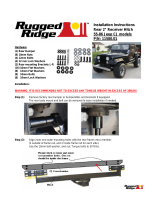
PARTS LIST:
Qty
Part Description
Qty
Part Description
1
Grille Guard Assembly
6
12mm Lock Washers
2
Frame Brackets
6
12-1.75mm Hex Nuts
1
Driver/Left Side Mounting Bracket
4
10-1.50mm x 30mm Hex Bolts
1
Passenger/Right Side Mounting Bracket
8
10mm x 27mm x 3mm Flat Washers
1
Driver/Left Top Bracket (for 14-15 MY)
4
10mm Lock Washers
1
Passenger/Right Top Bracket (for 14-15 MY)
4
10-1.50mm Hex Nuts
1
Driver/Left Top Bracket (for 16-18 MY)
2
8-1.25mm x 25mm Button Head Allen Bolts
1
Passenger/Right Top Bracket (for 16-18 MY)
6
8-1.25mm x 25mm Hex Bolts
2
50mm x 150mm Adhesive Foam Tapes
10
8mm x 24mm x2mm Flat Washers
2
12-1.75mm x 30mm Double Bolt Plates
6
8mm Lock Washers
2
12-1.75mm x 35mm Single Bolt Plates
2
8-1.25mm Nylon Lock Nuts
6
12mm x 24mm x 2.5mm Flat Washers
1
Allen Wrench S=5
Grille Guard
Part No. E0034S/B
Fits: 2014 - Current GMC Sierra 1500
Driver/Left
Mounting Bracket
(2) Frame Brackets
Driver/Left Top
Bracket (for 14-15 MY)
Passenger/Right Top
Bracket (for 14-15 MY)
(2) 12mm x 35mm
Single Bolt Plates
Passenger/Right Top
Bracket (for 16-18 MY)
(2) 12mm x 30mm
Double Bolt Plates
Passenger/Right
Mounting Bracket
Driver/Left Top
Bracket (for 16-18 MY)
EXCL. DENALI
REMOVE CONTENTS FROM BOX. VERIFY ALL PARTS ARE PRESENT.
READ INSTRUCTIONS CAREFULLY BEFORE STARTING INSTALLATION.
60-180 min
support@trailfx.com
1 866 638 4870
POLISHED STAINLESS STEEL – LIMITED LIFETIME
POWDER COATED BLACK – 3 YEARS
Cutting
Required
Drilling Not
Required
DO NOT OVER TORQUE. STANDARD OPERATING LOAD FOR TIGHTEN
BODY MOUNT NUTS & BOLTS VARIES FROM
45
TO
65
FOOT POUND.

www.TrailFX.com
Page 2 of 9 Rev 100118
INSTALLATION PROCEDURE:
DO NOT ATTEMPT INSTALLATION ALONE; PERSONAL INJURY OR DAMAGE TO THE VEHICLE MAY RESULT.
CUTTING MAY BE REQUIRED. ASSISTANCE IS HIGHLY RECOMMENDED. INSTALLATION MAY INTERFERE WITH
FRONT MOUNTED SENSORS.
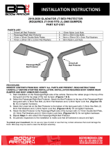
1. Start installation from the front of the vehicle. Locate and remove the screws attaching the ends of the plastic body panel,
(fascia), to the fenders, (Figures 1 & 2). NOTE: Fascia body panel fills the area between the headlights and the top of the
bumper and must be removed to access the bumper bolts.
2. From behind the bumper, release the clips attaching the fascia panel to the bottom of the grille and remove the panel,
(Figures 3 & 4).
3. Next, open the hood and remove the plastic cover from the top of the radiator and the grille, (Figure 5). Locate and remove
the hardware attaching the top and bottom of the grille, (Figures 6 & 7). Carefully pull the grille straight out from the vehicle.
4. Determine if the vehicle is equipped with tow hooks, (Figure 8). IMPORTANT: Tow hooks cannot be reinstalled with the
Grille Guard.
Tow Hook equipped vehicles:
a. On the passenger side, locate the (2) bumper bracket bolts from the top of the bumper, (Figure 9). Remove the
bottom bolt and loosen the top bumper bolt to help tilt the bumper and remove the long hex bolt through the tow
hook. Repeat this Step to remove driver side tow hook.
b. NOTE: If necessary, loosen and/or completely remove the outer support Brackets attaching the bumper to the
frame to help tilt the bumper forward, (Figure 10).
c. Once both tow hooks have been removed and the openings have been checked for Bracket clearance, reinstall the
bottom bumper Bracket bolts and support bracket hardware, if removed.
d. Only tighten the bottom bumper bracket bolts and outer support Bracket hardware at this time.
e. Proceed to Step 5.
Vehicles without tow hooks:
a. Cut out the lower portion of the indented area in both sides of the plastic bumper insert to clear the Brackets,
(Figures 11 & 12). IMPORTANT: Make several small cuts for best fit.
5. Starting on the passenger side, select (1) Frame Bracket. Insert the Bracket through the opening in the passenger side of
the plastic bumper, (Figures 13 & 14). Line up the (3) holes in the Bracket with the holes in the end of the frame.
6. Select (1) 12mm Double Bolt Plate, (Figure 15A). Insert the Bolt Plate into the end of the frame channel, through the (2)
holes in the side of the frame and out through the Bracket. Secure the Bracket to the Double Bolt Plate with (2) 12mm Flat
Washers, (2) 12mm Lock Washers and (2) 12mm Hex Nuts, (Figure 15B). Snug but do not fully tighten hardware at this
time. Repeat this Step to install the 12mm x 35mm Single Bolt Plate, (Figure 16A), into the remaining hole in the other side
of the frame channel and through the Bracket, (Figure 16B).
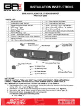
7. Next, select the passenger side Mounting Bracket, (Figure 17). Attach the Mounting Bracket to the bottom of the Frame
Bracket with (3) 8mm x 25mm Hex Bolts, (3) 8mm Lock Washers and (3) 8mm Flat Washers, (Figures 17 & 18). Do not
tighten hardware at this time.
8. Repeat Steps 5—7 to install the driver side Frame and Mounting Brackets.
9. Starting on the passenger side, locate and remove the top factory bumper bolt, (Figure 19). Depending on the model year of
the vehicle, select either the passenger side 14-15 Top Bracket or passenger side 16-18 Top Bracket, (Figure 20). Apply a
layer of Adhesive Foam Tape to the Top Bracket to protect the finish on the bumper, (Figure 21). Reuse the factory top
bumper bolt to attach the Top Bracket to the vehicle, (Figures 22 & 23). Leave hardware loose at this time.
10. Repeat Step 9 to attach the appropriate driver side Top Bracket to the top of the bumper bracket.
11. With assistance, hold the Grille Guard up in position on the outside of the Mounting Brackets. Attach the Grille Guard to the
Brackets with (4) 10mm Hex Bolts, (8) 10mm Flat Washers, (4) 10mm Lock Washers and (4) 10mm Hex Nuts, (Figures
24—26). Snug but do not tighten hardware.
12. Check the Grille Guard alignment with the vehicle. Adjust as required then tighten first the Frame Bracket hardware, then the
(6) 8mm Hex Bolts securing the Mounting Brackets to the bottom of the Frame Brackets. Do not fully tighten the Grille Guard
to Bracket hardware at this time.
13. Line up the outer bent end of the passenger side Top Support Bracket with the hole in the Grille Guard upright. Attach the
Top Bracket to the Grille Guard with (1) 8mm Button Head Bolt, (2) 8mm Flat Washers and (1) 8mm Nylon Lock Nut,
(Figures 24—26).
14. Repeat Step 13 to attach the driver side Top Support Bracket to the Grille Guard.
15. Level and adjust the Grille Guard and fully tighten all brackets to frame hardware only.
16. Temporarily remove the Grille Guard and reinstall the plastic body panel, (fascia), grille and cover.
17. Repeat Steps 11—15 to reinstall the Grille Guard.
18. Do periodic inspections to the installation to make sure that all hardware is secure and tight.

www.TrailFX.com
Page 3 of 9 Rev 100118
Passenger/right Installation Pictured
(Fig 1) Locate and remove screws attaching
ends of fascia body panel to front fenders
Front
(Fig 2) Remove the screws from the inside
of the fender to remove the body panel
Front
(Fig 3) From behind bumper release plastic
clips to remove fascia body panel
(Fig 4) Remove the fascia body panel to access the
top bumper bolts and remove tow hooks, if equipped
Front
(Fig 5) Remove the plastic cover (arrow)
Front
Front

www.TrailFX.com
Page 4 of 9 Rev 100118
Passenger/right Installation Pictured
(Fig 8) Opening for tow hook pictured
(Fig 7) Remove the top bolts from the grille
and carefully pull and remove grille
(Fig 6) Remove fascia and bottom
bolts attaching grille to the vehicle
Front
(Fig 10) Loosen and/or remove the support
bracket attaching the bumper to the frame to
help tilt bumper, (passenger side pictured)
Front
(Fig 9) Remove the bottom bolt on the
bumper Bracket, (passenger side pictured)
Front
Factory top
bumper bolt

www.TrailFX.com
Page 5 of 9 Rev 100118
Passenger/right Installation Pictured
(Fig 11) "No tow hook" model pictured
(Fig 12) Driver side cut out
illustrated for reference only
(Fig 15A) 12mm Double Bolt Plate
Front
(Fig 13) Frame Bracket w-Bolt Plates
(Fig 14) Driver side pictured without plastic
panel for instruction purposes only
Locate mounting holes
in end of frame for
factory tow hooks
Front

www.TrailFX.com
Page 6 of 9 Rev 100118
Passenger/right Installation Pictured
Fig 16A Single Bolt Plate
(Fig 18) Passenger side Mounting Bracket
attached to the bottom of the Frame bracket
Front
12mm Double Bolt Plate
(2) 12mm Flat Washers
(2) 12mm Lock Washers
(2) 12mm Hex Nuts
Front
(Fig 15B) Outer passenger side of
Frame Bracket with double bolt plate
Front
12mm Bolt Plate
12mm Flat Washer
12mm Lock Washer
12 mm Hex Nuts
(Fig 16B) Outer driver side of Frame
Bracket with single bolt plate
Bolt the Mounting Bracket
to the bottom of the Frame
Bracket with:
(3) 8mm x 25mm Hex Bolts
(3) 8mm Lock Washers
(3) 8mm Flat Washers
(Fig 17) Passenger side Mounting Bracket
attached to Frame Bracket illustrated
Front

www.TrailFX.com
Page 7 of 9 Rev 100118
Passenger/right Installation Pictured
(Fig 21) Adhesive Foam Tape
(Fig 20) Passenger side Top Brackets illustrated
Front
Passenger/Right Top
Bracket (for 14-15 MY)
Passenger/Right Top
Bracket (for 16-18 MY)
(Fig 22) Passenger side Top
Bracket for model years 14-15
Front
Reuse factory top bolt
(Fig 19) Remove top factory bumper bolts
Front
NOTE: On MY 16-
18, the end of the
bracket faces up.
(Fig 23) Passenger side Top Bracket
for model years 16-18
Front
Reuse factory top bolt

www.TrailFX.com
Page 8 of 9 Rev 100118
Passenger/right Installation Pictured
Complete Installation
Front
(Fig 26) Grille Guard attached to
passenger side Brackets (pictured with
MY 16-18 Top Bracket)
Bolt the Top Bracket to the
Grille Guard with:
(1) 8mm Button Head Bolt
(2) 8mm Flat Washers
(1) 8mm Nylon Lock Nut
(2) 10mm Hex Bolts
(4) 10mm Flat Washers
(2) 10mm Lock Washers
(2) 10mm Hex Nuts
(Fig 24) Passenger side Brackets
attached to Grille Guard
Front
Model year 14-15 Passenger
side Top Bracket
Model year 16-18 Passenger
side Top Bracket
Mounting holes for optional
parking sensor relocation
kit (available separately)
(Fig 25) Grille Guard attached to
passenger side Brackets (pictured with
MY 14-15 Top Bracket)
Front

www.TrailFX.com
Page 9 of 9 Rev 100118
1. Hardware’s are not of correct size.
In GMC / Chevrolet truck model 2006 & up, customer needs to reuse the factory body bolts to install the bracket. If your vehicle is not
GMC / Chevrolet 2006 & up, ensure that holes are not partially covered with any plastic grommet or rust? If it is, remove the plastic
grommet & rust from the thread holes & re-try the installation.
2. Mounting Bracket are not getting Installed properly.
In some cases Illustration images shown in Installation manual may not be the exactly same as per actual vehicle images ,also if Driver /
Passenger side mounting brackets are very identical in the design, suggest referring Parts Identification guide to avoid fitment issue.
3. Products are thumping / rattling after installation.
Ensure that all required mounting brackets / hardware’s are installed & tighten correctly. Suggest using white lithium / regular grease
between the metal to metal contact surfaces.
4. Side Bar is not aligning with vehicle / Step Pads are not aligning with vehicle doors.
Side bar may be interchanged or mounting brackets are not installed at the correct position in the vehicle. Refer Parts identification guide.
5. Missing / Excess Hardware.
Recheck hardware count as per the part list.
6. Product not installing properly.
Ensure make model year, cab length and bed size of your vehicle is listed in the application. All installation steps are followed correctly.
Check out these other TrailFX Products!! www.TrailFX.com
Periodically check the product to ensure all fasteners are tight and components are intact.
Regular waxing is recommended to protect the finish of the product.
Use ONLY Non-Abrasive automotive wax. Use of any soap, polish or wax that contains an abrasive is detrimental and can scratch the
finish leading to corrosion.
Aluminum polish may be used to polish small scratches and scuffs for Stainless Steel finish.
Mild soap may be used to clean the product for both
Stainless Steel and Black finish.
Keystone Automotive Operations Inc. (KAO) warrants this product to be free of defects in material and workmanship at the time of purchase by the
original retail consumer. KAO disclaims any other warranties, express or implied, including the warranty of fitness for a particular purpose or an
intended use. If the product is found to be defective, KAO may replace or repair the product at our option, when the product is returned prepaid,
with proof of purchase. Alteration to, improper installation, or misuse of this product voids the warranty. KAO’s liability is limited to repair or
replacement of products found to be defective, and specifically excludes liability for any incidental or consequential loss or damage.
/