
Installation guide
4-Line small business system
1080 with digital answering system and
caller ID/call waiting
1070 with caller ID/call waiting
1040 speakerphone

Congratulations
on purchasing your
new AT&T product.
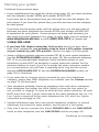
Before using this AT&T product, please
read the Important product information
in your User’s manual.
Please thoroughly read the installation
guide for all the installation
and troubleshooting information you
need to install and setup your new
AT&T product. You can also visit our
website at www.telephones.att.com
or call 1 (800) 222-3111.
In Canada, dial 1 (866) 288-4268.
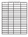
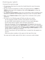
The form on the next page helps you to inventory your
new sets. Please have this with you if you need to call
customer service.
© 2007-2009 Advanced American Telephones. All Rights Reserved. AT&T and
the AT&T logo are trademarks of AT&T Intellectual Property licensed to
Advanced American Telephones, San Antonio, TX 78219.

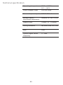
Model,
(circle one)
Location Serial number,
(found on the bottom of
the telephone base)
Purchase date
and place
1080 1070 1040
1080 1070 1040
1080 1070 1040
1080 1070 1040
1080 1070 1040
1080 1070 1040
1080 1070 1040
1080 1070 1040
1080 1070 1040
1080 1070 1040
1080 1070 1040
1080 1070 1040
1080 1070 1040
1080 1070 1040
1080 1070 1040
1080 1070 1040
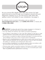
4-line small business system

STOP!
For customer service or product information, visit our website at
www.telephones.att.com or call 1 (800) 222-3111. In Canada, dial
1 (866) 288-4268.
CAUTION: To reduce the risk of fire or injury to persons or damage to
the telephone, read and follow these instructions carefully:
• Use only alkaline 9V batteries (size 1604A, purchased separately).
• Do not dispose of the battery in a fire. Like other batteries of this type, it could
explode if burned. Check with local codes for special disposal instructions.
• Do not open or mutilate the battery. Released electrolyte is corrosive and may
cause damage to the eyes or skin. It may be toxic if swallowed.
• Exercise care in handling batteries in order not to create a short circuit. Do not
allow conductive materials such as rings, bracelets, or keys to touch the battery.
The battery or conductor may overheat and cause harm.
• Use the battery identified for use with this product only in accordance with
the instructions and limitations specified in this manual.
• Observe proper polarity orientation between the battery and metallic contacts.
• Do not disassemble your telephone. There are no user-serviceable parts inside.
Refer to qualified service personnel for servicing.
Do you receive DSL (digital subscriber line) service for high-
speed Internet access through your telephone line(s) from your
telephone company? If so, you will need to add either DSL
splitters and/or microfilters to your installation. See page 9.

Table of contents
Planning your system .......................................................................................................................1
System planner ....................................................................................................................................4
Parts checklist (1040/1070/1080) ...........................................................................................5
Important information for DSL users ........................................................................................6
Professionally installed splitter for DSL lines ......................................................................9
Table/desktop installation .......................................................................................................... 10
Wall mounting .................................................................................................................................. 14
Directory card ................................................................................................................................... 16
Optional headset (purchased separately) ........................................................................... 17
Feature menu .................................................................................................................................... 18
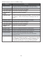
DTAD feature menu (1080 only) ..............................................................................................25
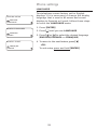
Menu operation ................................................................................................................................ 28
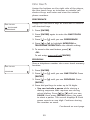
Phone settings .................................................................................................................................. 29
LANGUAGE ..................................................................................................................................... 29
One touch ........................................................................................................................................... 30
PREFERENCE .................................................................................................................................. 30
PROGRAM ....................................................................................................................................... 30
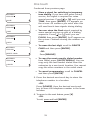
Phone settings .................................................................................................................................. 32
EXTENSION NUMBER ................................................................................................................. 32
RINGER ON/OFF ..........................................................................................................................33
RINGER TYPE .................................................................................................................................33
DELAY RING ................................................................................................................................... 34
AUTO-MUTE .................................................................................................................................... 35
TONE/PULSE.................................................................................................................................. 36
HOLD REMINDER ......................................................................................................................... 36
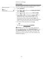
Time/date .......................................................................................................................................... 37
Special options ................................................................................................................................. 39
PRIME LINE ..................................................................................................................................... 39
AUTOMATIC MODE ..................................................................................................................... 39
SCROLL RATE ................................................................................................................................ 40
LCD CONTRAST ............................................................................................................................ 40
COVM ON/OFF, 1080 and 1070 only ............................................................................... 41
AREA CODE, 1080 and 1070 only ......................................................................................42
LINE GROUP .................................................................................................................................. 43
RESET ALL ....................................................................................................................................... 45
AUTO ATT SETUP (1080 only) ................................................................................................... 46
EVERY 1080=AA........................................................................................................................... 47
NO 1080=AA ................................................................................................................................. 47
PER 1080=AA ................................................................................................................................ 48
AUTO ATT DELAY ......................................................................................................................... 49
DAY/NIGHT TIMES ....................................................................................................................... 50
RESET AUTO ATT, (1080 only) ...............................................................................................51
SYS EXT mailbox (1080 only) .................................................................................................... 52
About system extension mailboxes ................................................................................... 52
System Extensions ......................................................................................................................52
AUTO SETUP .................................................................................................................................. 53
CUSTOM SETUP ............................................................................................................................53
UNASSIGN MBOXES ................................................................................................................... 54
REMOVE EXT MSGS..................................................................................................................... 55
To delete all messages from one SYS EXT telephone .............................................. 55
To delete all messages of all SYS EXT phones ............................................................ 56
DTAD setup (1080 only) ............................................................................................................... 57
ANSWER STATUS ......................................................................................................................... 57
ANSWER DELAY ........................................................................................................................... 58
TOLL SAVER ................................................................................................................................... 58

REMOTE CODE .............................................................................................................................. 59
MESSAGE LENGTH....................................................................................................................... 60
MESSAGE ALERT .......................................................................................................................... 61
CALL SCREENING ........................................................................................................................ 62
DTAD INTERCEPT .........................................................................................................................62
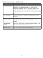
DTAD FEATURE MENU (1080 only) ......................................................................................... 63
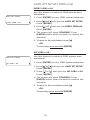
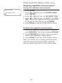
Outgoing announcements for auto attendant ............................................................. 65
Outgoing daytime announcement ...................................................................................... 66
Outgoing nighttime announcement .................................................................................. 68
Directory announcement.........................................................................................................70
Share system announcements ............................................................................................. 72
Download system announcements .................................................................................... 73
Centrex .................................................................................................................................................74
CONSOLE ........................................................................................................................................ 74
CSL DELAY RING .......................................................................................................................... 75
Language .............................................................................................................................................76
Centrex operation ........................................................................................................................... 77
Set ring delay duration ............................................................................................................ 78
About a fax machine ..................................................................................................................... 79
Adding a fax machine ............................................................................................................... 79
Using a fax switch ...................................................................................................................... 79
Technical specification ................................................................................................................. 80
Appendix A, Glossary .................................................................................................................... 81
Appendix B, Optional spare battery (purchased separately) ..................................... 84
Troubleshooting ............................................................................................................................... 86
Index ...................................................................................................................................................... 97

1
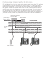
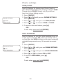
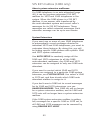
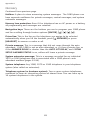
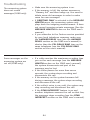
Planning your system
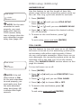
Your system can have up to 16 telephones (models 1040, 1070 or 1080,
purchased separately) and up to 19 telephone numbers. Your system can
have all the system features (intercom call, voice page, call transfer, multiple
telephone conference call, DTAD mailbox, and auto-attendant).
To set up a small business system
Purchase your telephones (model 1040, 1070 or 1080), arrange for your
telephone lines, and purchase any line outlet adapters and additional
telephone line cords you might need. To order them, visit our website at
www.telephones.att.com
, or call
1 (800) 222-3111
. In Canada, dial
1 (866) 288-4268.
NOTES:
• All connected phones must have the same line 1 phone number for the
intercom and paging features to work.
Line 1
Line 2
Line 3
Line 3, 4
System
telephone
System
telephone
System
telephone
System
telephone
Line 1, 2
Line 4
• The total length of telephone wiring used for Line 1 MUST NOT be more
than 600 feet as it may cause interference with the advanced features of
this telephone.
• You must have modular telephone jacks and electrical outlets not
controlled by wall switches near where you are installing the phones.
• To use the auto-attendant function (see the Auto attendant operation
section on the 1080 user’s manual), you must purchase at least one
1080 telephone, and we recommend it be set up as Extension 11 (see the
EXTENSION NUMBER section on page 32).
• If a 1080 extension is an active auto attendant and its auto attendant is
answering or directing a call, playing or recording an announcement or
message, the LINE light will flash continuously (two short flashes followed
by one long flash). To interrupt the auto attendant, press the flashing LINE
button on this 1080 telephone to talk to the caller on that line, or press
any other LINE button to disconnect this call and make a new call on
another line.
Continued on next page

2
Planning your system
Continued from previous page
• If your establishment has single-line phone jacks (page 11), you must purchase
two-line adapters (model 16598, part number 89-0071-00).
If you have two or three phone lines, you will need one two-line adapter for
each phone. If you have four phone lines, you will need two two-line adapters
for each phone.
If you have one-line phone jacks, and four phone lines, you will also need to
purchase one short telephone line (model 51920, part number 89-0052-00)
or equivalent for each phone. If some phones are being wall mounted, you
may need more short telephone line cords. To order them, visit our website at
www.telephones.att.com, or call 1 (800) 222-3111. In Canada, dial
1 (866) 288-4268.
•
If you have DSL (digital subscriber line) service and if you have more
than three telephones, you probably need to have a DSL splitter installed
at your location by your DSL provider. Please see page 9 of this guide.
• Assign a different system extension number EXT XX to each system telephone
(see the EXTENSION NUMBER section on page 32). We recommend assigning
EXT 11 to an auto-attendant telephone. Every individual phone in your
telephone system MUST be assigned a unique extension number for the
intercom feature to work. If you try to assign the same extension number
to a second phone, you will hear a repeating short ring and the screen
displays ASSIGN NEW EXT #. See the EXTENSION NUMBER section on
page 32 for directions.
• If you subscribe to Centrex service provided by your local telephone
company, assign that 1080 telephone as a console (see the Centrex section
on page 74 for directions).
• Your telephone probably shares its telephone lines with other extensions.
Each telephone line button has LEDs (lights) to show the line status (in
use, on hold, or ringing). To have an accurate line status indication, all units
MUST have their Line 1 jacks connected to the same telephone line (i.e. L1),
Line 2 jacks connected to the same telephone line (L2), and Line 3 jacks
connected accordingly to (L3).
• System telephones have their own private telephone numbers, or several
extensions can share the same number, and be part of a line group.
• Only Line 4 can be a private line. Select
PRIVATE LINE in the LINE GROUP
menu on that telephone (see the LINE GROUP section on page 43).
Continued on next page

3
Planning your system
Continued from previous page
• All extensions that share the same line should share the same line group
number (4-15).
• You can connect fax machines or other non-system devices to
AUXL3 or
AUXL4 on the back of the telephone (also called data ports), so they can
access line 3 or 4.
• See
Optional spare battery, page 84 for information about installing spare
batteries to maintain basic telephone features in case of a power failure.
• Refer to the
Feature menu section, page 18, to customize each system
telephone.
•
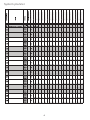
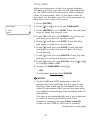
The chart on the following page will help you plan your system.
- List the extension number, location, and model for each phone.
- For each 1080, decide whether you want it to be an auto attendant.
- Decide which phone numbers each extension should have.
- Plan your line groups. This is necessary only if all telephone lines are not
attached to all telephones. See LINE GROUP, page 43, for more information.
- Decide which 1070 and 1040 extensions will be assigned to which 1080
system extension mailbox (see the Forwarding to DTAD mailbox section
on the 1070 or 1040 user’s manual).
- Decide if any phones will have private lines. A private line only appears on
one set.
- Write your phone numbers in the spaces at the top of the chart.
You may want to make copies of this chart, in case your needs change.

4
System planner

5
Tool needed (optional)
You will need a Phillips screwdriver to install your optional backup battery.
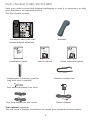
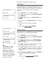
Parts checklist (1040/1070/1080)
Save your sales receipt and original packaging in case it is necessary to ship
your telephone for warranty service.
The box should include:
Telephone base with wall
mount bracket attached
Handset
One short telephone line cord
Two long telephone line cords
Handset coiled cord
Power adapter
Replacement directory card (In
bag with user’s manual)
User's manual
Quick reference guide
Installation guide
Quick reference guide
1080
4-Line small business
system with digital
answering system and
caller ID/call waiting
User’s manual
1080
4-Line small business
system with digital
answering system and
caller ID/call waiting

6
Important information for DSL users
Do you receive DSL (digital subscriber line) service for high-speed Internet
access through your telephone line(s) from your telephone company? If
so, add either DSL splitters and/or microfilters to your installation. Without
these DSL splitters and/or microfilters, your telephone service will interfere
with your data reception, and your data reception will interfere with your
telephone sound quality and the advanced features that work by sending data
signals over Line 1 (such as intercom, hold, and line privacy).
If you have fewer than four telephones, if Line 1 can be a non-DSL line, and
if there is no alarm system, you can use microfilters between each telephone
and each telephone wall jack.
If your system meets any of the following three criteria, you will need DSL
splitter(s) installed near where the telephone lines come into the building.
You will need one for each DSL line. This usually requires a professional
installer.
1) If you have more than three telephones in your system, you probably
need the help of a professional installer. For each telephone line connected
to more than three telephones of any type or brand, you will need to install
a DSL splitter near where the phone lines come into the building. This usually
requires a professional installer.
2) If you need line 1 to be a DSL line, you probably need the help of a
professional installer. The telephone system information is carried on Line
1. Therefore, you must connect the same telephone line to the Line 1 jacks
of all telephone sets. This telephone information and the Internet access
information cannot coexist on the same telephone line without a DSL splitter
that should be installed near where the phone lines come into the building.
This usually requires a professional installer. Do not use microfilters on Line
1 as they interfere with telephone operation.
3) If you have an alarm system, you probably need the help of a professional
installer. Alarm systems use telephone lines. This telephone system and the
alarm system cannot share the same telephone line.
Other DSL information: Voice and high-speed data access can share your
telephone lines because the Internet modems use high-frequency data signals
and telephones use low-frequency voice signals. However, to provide high
quality voice and to enable the telephones to work as an integrated system,
most telephones need to have the high frequency signals removed. You will
need either DSL splitters or filters to remove these signals.
Continued on next page

7
Important information for DSL users
Continued from previous page
Use splitters to separate the high-frequency DSL signals from the low-
frequency signals used by the telephone equipment. Although some splitters
can be installed by end users, most DSL splitters are installed by the
telephone company.
You can use microfilters at each individual phone jack or telephone set.
Telephone service providers typically supply them for free to self installers.
However, if you install more than three microfilters on system phones, the
sound quality and advanced features’ operation may suffer. If you have
more than three telephones, you will probably need to have your telephone
company install the DSL splitter near where your telephone lines come into
the building.
For only one or two DSL lines, install the DSL filter into the L3/L4 jack on the
back of the telephone.
If your system will only use two or three telephone lines, plug a single non-
DSL telephone line into the L1/L2 jack. If the lines have DSL, be sure to use
the microfilter(s) on lines 3 and/or 4.
If there are two telephone lines, one of which is DSL, and both appear at a
single wall jack, use a triplex adapter to separate the lines at the wall jack. If
you need help doing this, visit our website at www.telephones.att.com
or call 1 (800) 222-3111. In Canada, dial 1 (866) 288-4268.
If you must install a DSL line into the L1/L2 jack on the back of the
telephone, use a DSL splitter.
Lines 1 and 2 share a telephone jack. If it is necessary to install a DSL line
for telephone line 1 or line 2, you will need additional equipment to avoid
interference. Any telephone line connected to the L1/L2 jack cannot have
a microfilter. It must have a DSL splitter. A DSL splitter allows the data and
voice signals to use the same telephone line without interfering with each
other. Use a dual-line DSL splitter or a two-line DSL filter. If you need help
doing this, visit our website at www.telephones.att.com or call
1 (800) 222-3111. In Canada, dial 1 (866) 288-4268.
Installing a DSL splitter (not a microfilter) as close as possible to the
protection block or network interface (where the telephone line enters the
house or building) may resolve DSL interference. (It may be necessary to use a
DSL splitter intended for outdoor use.)
Continued on next page

8
Important information for DSL users
Continued from previous page
AT&T cannot supply the DSL splitter. Please contact your DSL service provider
or professional contractor for details about obtaining and installing a DSL
splitter. Your DSL service provider may require you to bear any installation
costs. AT&T and the manufacturer of this product have no affiliation with your
DSL provider and the type or quality of services they offer. Installation must
be performed at your own expense. AT&T cannot provide installation or after
sale support.
NOTE: If your DSL service provider cannot supply a DSL splitter, it is
possible to purchase an outdoor DSL splitter over the Internet.
If you are a new DSL customer, your DSL service provider will probably
ask you whether you have more than one telephone line in your home or
business, or whether you are installing a telephone system. If you answer
yes, your DSL service provider will probably advise you that you will need
a splitter. In most cases, your DSL service provider will supply you with the
proper splitter for your specific situation. When installed properly, the DSL
filter helps eliminate any interference between the DSL signal and the signals
sent by your telephone system.
AT&T shall not be responsible for the cost of installation, any damages, lost
business, direct or indirect expenses accrued or associated with installation,
or other compatibility issues that may arise as a result of using this product
while you subscribe to DSL service.

9
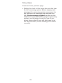
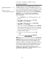
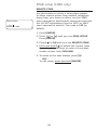
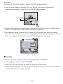
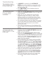
Professionally installed splitter for DSL lines
DSL telephone lines that are used in the system must have either DSL splitters
or microfilters. If you are using the DSL line for line 1, or if you have more
than three telephones, or if you have an alarm system, you probably need a
DSL splitter. Install this splitter (also known as the network interface device
or NID) near where the telephone lines enter the building. This will allow the
DSL telephone line to be split into two different lines, one for your system
telephones, and the other for your data device. Please seek the assistance of
your DSL service provider or professional contractor to do this installation.
DSL Modem
From Telco
Central Office
(Network)
Network Interface
Device (NID)
Outside Wall
DSL Splitter
Line
Data
Voice
Inside Wall
To all phones (voice only)
To DSL modem
only
OUTDOORS
INDOORS

10
Table/desktop installation
Connect the two long telephone line cords to the telephone. How
you connect the telephone line cords to the wall is determined by your
telephone service. Determine if you have one or two-line telephone wall
jacks and if you receive DSL (digital subscriber line) service. If one or more
of the telephone lines has DSL service, see Important information for DSL
users, pages 6-8. Use only the line cords that come with the phones. If you
need additional cords, visit our website at www.telephones.att.com
or call 1 (800) 222-3111. In Canada, dial 1 (866) 288-4268.
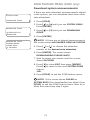
If you have two-line wall jacks, you can just plug the line cords into the
wall jacks. Use Illustration A on page 11.
If you have one-line wall jacks, you need to purchase one or two two-
line adapters. Adapters are available at retail stores, by visiting our
website at www.telephones.att.com or by calling
1 (800) 222–3111. In Canada, call 1 (866) 288-4268.
You need two adapters if you have four telephone lines and use
the AUX jacks (on the back of the telephone) for equipment like fax
machines. You will also need an additional short 2- or 4- conductor
telephone line cord for this installation. Use Illustration B on page 11.
You need one adapter if you use both AUX jacks for installing your
phones. Use Illustration C on page 12.
NOTE: To purchase 2-line adapters (model 16598, part # 89-0071-00),
you can visit our website at www.telephones.att.com or call
1 (800) 222-3111. In Canada, dial 1 (866) 288-4268. You can
purchase 2-line adapters at some electronic and hardware stores.
1.
•
•
—
—

11
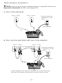
Table/desktop installation
A: Two 2-line wall jacks
B: Four one-line wall jacks with two 2-line adapters.
NOTE: If one or more of your telephone lines is using DSL service, see
Important information for DSL users, pages 6-8.
In this installation, four-conductor telephone line cord (RJ 14) is gray.
The long cords supplied with the phone are four-conductor cords.
Two-line adapter
Power adapter
Electrical outlet not
controlled by a wall
switch
Line 1Line 2Line 3Line 4
Power adapter
Electrical outlet not
controlled by a wall
switch
Line 2 + Line 1Line 4 + Line 3

12
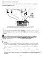
Table/desktop installation
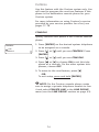
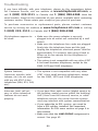
2. Connect the power adapter to the telephone. Plug the small end of the
power adapter into the jack labeled POWER on the back of the phone.
Plug the large end into a standard electrical outlet not controlled by a wall
switch.
Use only the power adapter provided with this product. To obtain a
replacement, visit our website at www.telephones.att.com or call
1 (800) 222-3111. In Canada, dial 1 (866) 288-4268.
NOTES:
1. The phone runs through initialization any time it is reconnected to AC
power if a working battery is not installed (for example, after a power
failure or when the unit has been unplugged). See page 84, Optional
spare battery.
2. Connect power to each telephone sequentially so that each set is
assigned a unique extension number. If all sets are powered up at the
same time, the same extension numbers could be assigned to more
than one set. Please see page 32 for information on assigning extension
numbers.
C: Four one-line wall jacks with one 2-line adapter using the
telephone AUX jacks.
In this installation, four-conductor telephone line cord (RJ 14) is gray.
The long cords supplied with the phone are four-conductor cords.
Two-line adapter
Power adapter
Electrical outlet not
controlled by a wall
switch
Line 1Line 2Line 3Line 4

13
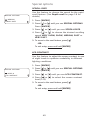
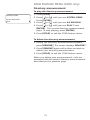
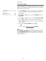
3. Check the extension number. Once you have attached the Line 1 telephone
line and AC power to the set and the wall outlets, the set automatically
assigns the next available extension number, and shows it in the second
line of the display. Plug in the phones in the same order as the extension
numbers you assigned on the system planner, (see page 4).
4. Connect the handset cord. Plug one end of the coiled handset cord into
the HANDSET jack on the left side of the phone. Plug the other end into
the handset and hang up.
5.
Check for dial tone. Lift the handset and listen for a dial tone. If you
cannot hear a dial tone, please see Troubleshooting beginning on page 86
for details.
6. Identify lines. To identify the telephone lines, press [ SPEAKER], then
the [LINE 1] key. Call one of the telephone numbers. If there is a busy
signal, it confirms that line 1 is the number called. If line 2 rings, line 2 is
the number called. Use the same steps to identify the other two telephone
lines.
AT&T shall not be responsible for the cost of installation, any damages, lost
business, direct or indirect expenses accrued or associated with installation,
or other compatibility issues that may arise as a result of using this product
while you subscribe to DSL, Fiber optic, VoIP (Voice over Internet Protocol), or
cable telephone service.
Table/desktop installation

14
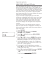
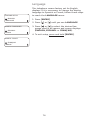
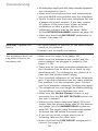
Wall mounting
The telephone base comes with the bracket mounted for table/desktop
use. To mount the telephone on a wall, you will need a telephone outlet
wall mounting plate with mounting studs. This mounting plate is available for
purchase from many hardware and consumer electronics retailers and may
require professional installation.
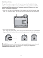
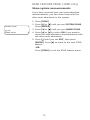
1. Press on the tabs in the direction of the arrows and pull the bracket away
from the telephone base. You do not need the bracket for wall mounting.
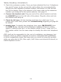
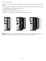
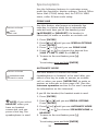
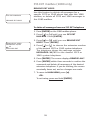
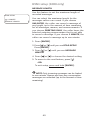
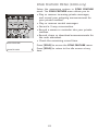
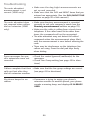
Getting started
Spare battery installation
Polarity label
7
+
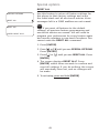
2. Reverse the handset tab.
Hold down the switch hook, then pull out the handset tab and rotate it 180
degrees. Push the handset tab down into the grooves so it settles into position.
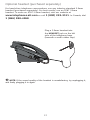
NOTE: If you receive DSL service for high-speed Internet access through
your telephone line(s) from your telephone company, see Important
information for DSL users, pages 6-8.
Handset tab
Switch hook
Page is loading ...
Page is loading ...
Page is loading ...
Page is loading ...
Page is loading ...
Page is loading ...
Page is loading ...
Page is loading ...
Page is loading ...
Page is loading ...
Page is loading ...
Page is loading ...
Page is loading ...
Page is loading ...
Page is loading ...
Page is loading ...
Page is loading ...
Page is loading ...
Page is loading ...
Page is loading ...
Page is loading ...
Page is loading ...
Page is loading ...
Page is loading ...
Page is loading ...
Page is loading ...
Page is loading ...
Page is loading ...
Page is loading ...
Page is loading ...
Page is loading ...
Page is loading ...
Page is loading ...
Page is loading ...
Page is loading ...
Page is loading ...
Page is loading ...
Page is loading ...
Page is loading ...
Page is loading ...
Page is loading ...
Page is loading ...
Page is loading ...
Page is loading ...
Page is loading ...
Page is loading ...
Page is loading ...
Page is loading ...
Page is loading ...
Page is loading ...
Page is loading ...
Page is loading ...
Page is loading ...
Page is loading ...
Page is loading ...
Page is loading ...
Page is loading ...
Page is loading ...
Page is loading ...
Page is loading ...
Page is loading ...
Page is loading ...
Page is loading ...
Page is loading ...
Page is loading ...
Page is loading ...
Page is loading ...
Page is loading ...
Page is loading ...
Page is loading ...
Page is loading ...
Page is loading ...
Page is loading ...
Page is loading ...
Page is loading ...
Page is loading ...
Page is loading ...
Page is loading ...
Page is loading ...
Page is loading ...
Page is loading ...
Page is loading ...
Page is loading ...
Page is loading ...
-
 1
1
-
 2
2
-
 3
3
-
 4
4
-
 5
5
-
 6
6
-
 7
7
-
 8
8
-
 9
9
-
 10
10
-
 11
11
-
 12
12
-
 13
13
-
 14
14
-
 15
15
-
 16
16
-
 17
17
-
 18
18
-
 19
19
-
 20
20
-
 21
21
-
 22
22
-
 23
23
-
 24
24
-
 25
25
-
 26
26
-
 27
27
-
 28
28
-
 29
29
-
 30
30
-
 31
31
-
 32
32
-
 33
33
-
 34
34
-
 35
35
-
 36
36
-
 37
37
-
 38
38
-
 39
39
-
 40
40
-
 41
41
-
 42
42
-
 43
43
-
 44
44
-
 45
45
-
 46
46
-
 47
47
-
 48
48
-
 49
49
-
 50
50
-
 51
51
-
 52
52
-
 53
53
-
 54
54
-
 55
55
-
 56
56
-
 57
57
-
 58
58
-
 59
59
-
 60
60
-
 61
61
-
 62
62
-
 63
63
-
 64
64
-
 65
65
-
 66
66
-
 67
67
-
 68
68
-
 69
69
-
 70
70
-
 71
71
-
 72
72
-
 73
73
-
 74
74
-
 75
75
-
 76
76
-
 77
77
-
 78
78
-
 79
79
-
 80
80
-
 81
81
-
 82
82
-
 83
83
-
 84
84
-
 85
85
-
 86
86
-
 87
87
-
 88
88
-
 89
89
-
 90
90
-
 91
91
-
 92
92
-
 93
93
-
 94
94
-
 95
95
-
 96
96
-
 97
97
-
 98
98
-
 99
99
-
 100
100
-
 101
101
-
 102
102
-
 103
103
-
 104
104


AT&T 1040 User manual
- Category
- Headphones
- Type
- User manual
Ask a question and I''ll find the answer in the document
Finding information in a document is now easier with AI