Unique Home Designs 1S1001CL1BHP5A Installation guide

Category
Holders
Type
Installation guide
Premium Security Door Installation
SURFACE MOUNT
IMPORTANT: Read the complete installation instructions
before proceeding with installation.
• Installation may require two people when lifting and installing the door
• Use appropriate protective equipment, including safety glasses
• Children should not be allowed in work area
• Failure to install door correctly could result in injury
Parts and Recommended Tools
Recommended Tool List:
• Measuring tape
• Pencil
• Level
• Drill and drill bits*
(1/8", 5/32", 3/16")
• Flat-blade screwdriver
• Phillips head screwdriver
• One-way screw driver
and remover
• Square
• Tin snips/aviation snips
• Box knife
• Safety glasses
• Wood blocks and shims
• Paintable caulk and caulk gun
4" One-Way Screws
Touch-up Paint
One-Way Driver Tool
Self-tapping screws
#10 3-1/2" Dry wall screws (2 pcs.)
#8 Black screws (8 pcs.)
6" x 36" Cardboard Threshold Template
Parts:
A) Hinge-side jamb
B) Door slab
C) Lock-side jamb
D) Top header jamb
E) Bottom bar
F) Threshold plate
G) Multi-blade bug sweep
H) Touch-up paint
I) One-way driver tool
J) 4" one-way screws
(12 pcs.)
K) #10 3-1/2" drywall screws
(2 pcs.)
L) #8 black screws (8 pcs.)
M) 6" x 36" cardboard
threshold template
*Drill bits should be a minimum 4" in length
4" one-way screws (12 pcs.)
CA
E
D
F
G
B
M
H
L
I
K
J
Determining Your Build Out Area
1
Determine Type and Readiness of Mounting Surface
Your new security door will require a minimum mounting
surface of 1" on the trim above, and on both sides of your
entry door. Mounting screws must be secured to a stud in
the wall. Review diagrams below, and determine which one
most resembles the trim around the entry door to which you
will mount your security door.
Inspect Your Entryway for Obstructions
Check for any obstructions above and around your entryway
that may prevent the outward swing of your new security
door, and/or its installation, such as:
Light xtures
Door bell
Low overhang
Door handle of your existing entry door
Trees, bushes, or hanging plants
Page 1
or or
or
Ready for installation
Entry Door Jamb
Entry Door
Stucco 2 (Top View)
Stucco
Pop-Out
1" minimum
mounting
surface
1" minimum
mounting
surface
This application will require 6" screws (Sold separately)
StudStud
Entry Door Jamb
Entry Door
Sloped Trim (Top View)
Sloped Trim*
Stud
Stud
Entry Door Jamb
1" minimum
mounting
surface
1" minimum
mounting
surface
Entry Door
Flat Trim (Top View)
Flat Trim
StudStud
Entry Door Jamb
Entry Door
Stucco 1 (Top View)
Stucco
Pop-Out
1" minimum
mounting
surface
1" minimum
mounting
surface
StudStud
Entry Door Jamb
Brick molding trim
Entry Door
Brick Molding (Top View)
StudStud
1" minimum
mounting
surface
1" minimum
mounting
surface
mounted between stucco pop-outs
mounted to front surface of stucco pop-outs
MK615 09212012
Ask an Associate for details or visit the Millwork Desk.
Determining Your Threshold Conguration
2
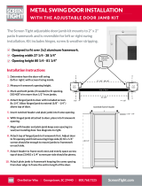
Look at your existing entry door threshold and use the diagrams below to determine which threshold conguration best applies
to your entryway. This will determine whether a bottom bar is or is not required for your security door.
The concrete extends at least
7/8" further than your trim.
The existing threshold sticks out
beyond the trim by 3/16" or less.
The existing threshold extends
beyond the trim by 7/8" or more.
The concrete and threshold sets
back behind the trim.
The concrete is set back and lacks
space to mount to the threshold plate.
The existing threshold extends past
the trim between 3/16" and 7/8".
Preparing Your Security Door
3
Glass Removal
If your door includes glass, remove it before
you start the installation procedure. Loosen
(do not remove) each screw. Carefully hold the
glass panel in place and rotate each clip 90°.
Carefully remove the glass panel and store it in a
safe place during installation.
Handleset Attachment
Following the manufacturer's instructions,
install your choice of 2-3/8" backset handle
and lock set (Sold separately). Fully extend
the lock bolts into the "locked" position on
the security door (B).
Rotate
clips 90°
Installing the Hinge-Side Jamb
4
For Left Swing Door For Right Swing Door
Primary
Entry Door
Primary
Entry Door
Jamb mounting
Position hinge-side jamb (A) on the desired side of the opening for
your door swing. Allow for a 1/8" gap between the hinge-side edge of
jamb and inside-edge of your mounting surface.
Note: There should be a minimum of 2-3/4" space below the hinge
side jamb and below the entire width of the door to allow space for
the bottom bar (attached in Step 7). It is okay to move the doors
up within the doorway to ensure this space, as long as the top of
the jambs do not go beyond the top-edge of your trim framing. If
a 2-3/4" space exists across the entire doorway, skip to the next
paragraph. Otherwise, position bottom bar (E) on the ground in front
of the doorway with the legs pointing up. Position the hinge-side jamb
assembly (A) on the inactive side of the door, sliding the jamb over the
bottom bar leg to correctly position the jamb. This alignment will be
repeated for the active side jamb. See diagram below:
Important: All jambs must be positioned to allow secure mounting to
your trim framing around the opening.
Make certain hinge-side jamb is plumb. Mark the location of the 1 & 2
mounting holes for hinge-side jamb, by inserting a screw through the
jamb and either making a dent or scratching the mounting surface.
Set the hinge-side jamb aside and, where marked, pre-drill the two
holes, using a 3/16" drill bit.
Support Jamb with temporary screws:
Return the hinge-side jamb to position, verify again that it is plumb,
and install two of the #10 3-1/2" dry wall screws (K) supplied into
holes 1 & 2 (see diagram at top left), and temporarily mount the hinge-
side jamb (A). These screws are inserted only to hold the security
door frame plumb while test tting the door, and will be removed and
replaced with one-way screws, later in this step.
Hang the door to test t:
Holding the door open at more than a 90° angle (see diagram at
center left), hang the security door (B) onto the hinge pins of the
hinge-side jamb (A), starting with the bottom pin rst (see diagram at
bottom left). Ensure that door is fully seated on hinges.
Place a level across the top of the door, to verify that the security door
is level, then re-verify that the hinge-side jamb has remained plumb
during the hanging of the security door. The door will be removed in
Step 6, then reinstalled in Step 9 . If the door is not plumb vertically
and/or horizontally, remove door panel and re-position jamb.
Hinge side jamb installs
opposite entry door handle
Note: verify
that direction of
hinge pins match
illustration
This side up
1
3
4
2
A
More than 90°
Top View
A
B
Jamb-side
hinge
Door-side
hinge
A
B
Hinge side jamb installs
opposite entry door handle
Note: verify
that direction of
hinge pins match
illustration
This side up
1
3
4
2
A
More than 90°
Top View
A
B
Jamb-side
hinge
Door-side
hinge
B
A
E
A
C
Insert bottom bar legs into the left
and right door jambs
Bottom Bar Required Bottom Bar NOT Required
Page 2
Continued
The contour of door framing varies, making it necessary to cut the threshold plate (F) to t. We recommend cutting a cardboard template to t the opening rst,
to avoid cutting the threshold plate incorrectly.
Lay provided cardboard template (M) on top of the bottom bar and push into existing threshold, as far as it will go. Using a straight edge, mark the template at
the various widths of your existing molding and trim at both ends.
Move template so that front edge is ush to the front edge of bottom bar (it is okay to bend template to allow to t the shortest width between your molding and
trim). Mark at the various corners of your existing molding and trim.
1
2
3
Continued
4
Secure Hinge-side Jamb with One-way Screws:
Pre-drill two 3/16" holes, 1-1/4" deep, into the entryway trim mounting surface, through holes 3 & 4 of the hinge-side jamb. Install two one-way screws
(J) into holes 3 & 4, securing the jamb to the entryway trim, using your drill and the supplied one-way driver tool (I).
Remove the two #10 3-1/2" dry wall screws (K) previously installed into the hinge-side jamb (holes 1 & 2 in the diagram). Drill two 3/16" holes, 1-1/4"
deep, into the entryway trim mounting surface, through holes 1 & 2. Install two one-way screws (J) into holes 1 & 2 using your drill and the supplied
one-way driver tool (I).
Installing the Lock-Side Jamb
5
Jamb Alignment
Align the lock holes, in the lock-side jamb (C), with the lock bolts extended. Maintain
a space between door (B) and the lock-side jamb (C) equal or similar to the space
between the door (B) and hinge-side jamb (A), from top to bottom. Make sure the
lock-side jamb is plumb, then mark the location of mounting holes 5 & 6 of the jamb, by
inserting a screw through the jamb and either making a dent or scratching the mounting
surface. Set the lock-side jamb aside and, where marked, pre-drill the two holes, using
a 3/16" drill bit.
Temporary Screws
Return the lock-side jamb to position, verify again that it is plumb, and install two #10 3-1/2" dry wall screws (K) supplied
into holes 5 & 6 (see diagram at left), and temporarily mount the lock-side jamb (C). These screws are inserted solely to
temporarily hold the jamb plumb.
Permanent Screws
Pre-drill two 3/16" holes, 1-1/4" deep, into the entryway trim mounting surface, through holes 7 & 8 of the lock-side
jamb. Install two one-way screws (J) into holes 7 & 8, using your drill and the supplied one-way driver tool (I).
Remove the two #10 3-1/2" dry wall screws (K) previously installed into the lock-side jamb (holes 5 & 6 in the
diagram). Pre-drill two 3/16" holes, 1-1/4" deep, into the entryway trim mounting surface through holes 5 & 6. Install
two one-way screws (J) into holes 5 & 6 using your drill and the supplied one-way driver tool, being careful to insure
that the jamb does not move and maintaining the 1/8" to 1/4" gap between the door and the jamb.
Gap between door (B) and both
side jambs (A & C) should appear
equal on each side with a
minimal reveal of 1/8", up to a
maximum reveal of 1/4"
Hinge side
Lock side
5
7
8
6
CA
B
Installing the Top/Head Jamb
6
Place the top head jamb (D) above the door (B) and between the two side jambs
(A & C). Take care to make sure that a minimum of 1/8" reveal is consistent on both sides
jambs (A & C) as well as on the top head jamb (D). Spacing should be equal from left to
right and above the door. Mark the location of the mounting holes. Set the top head jamb
(D) aside and, where marked, pre-drill 3/16" holes 1-1/4" inches deep. Return top head
jamb to position and fasten to mounting surface using the provided one-way screws (J)
and the supplied one-way driver tool (I).
D
C
A
B
Installing the Bottom Bar
7
Page 3
Note: If you will NOT be installing the bottom bar as determined in step 2, discard the bottom bar and skip to step 9,
otherwise, remove door from hinges and set aside.
Bottom Bar Placement
The bottom bar (E) will need to be installed 1/8" to 1/4" lower than
the existing doorway so that there is a slope to the threshold. This
allows any moisture to drain away from the door.
Bottom Bar Installation
Insert bottom bar legs into the left and right door jambs. Adjust the bottom bar to
the correct height. Install bottom bar (E) using two #8 self-tapping screws (L) as
shown. Keep your drill on a low speed so the threads do not strip.
E
A
C
Insert bottom bar legs into the left
and right door jambs
Installing the Threshold Plate
8
10
Using a box knife, cut template to shape of molding and trim revealed by the markings. Test t the template. (It should lay across the bottom bar, with the front
edge ush to the front edge of the bottom bar, and t in and around the corners of the existing molding and trim.)
Once you have created a good template, use the template to mark the threshold plate.
Using tin snips/aviator snips, cut threshold plate to match the shape of the template (6). Position threshold plate to extend across the bottom bar and into the
existing threshold. Use 1/8" drill bit to pre-drill holes for mounting screws. Attach threshold plate to existing threshold using the provided screws (L).
4
5
6
Existing door contour Make cardboard template Fit template to contour Cut template to contour Mark threshold plate Cut threshold plate to t
1 2 3 4 5 6
Installing the Door
9
Hang the security door (B) on the jamb hinges (A),
holding the door open at more than a 90° angle
(see diagram below), starting with the bottom pin rst.
More than 90°
Top View
A
B
Jamb side (A) hinge
Door side (B) hinge
Leveling Washers
Installing the Bug Sweep
Open the door. Slip the multi-blade bug sweep (G) onto the bottom of the door. Hold sweep in place and close the door.
Allow the sweep to fall and sit resting on the threshold plate (F). Note: Be sure there is not a gap between the sweep and the
threshold plate and that the sweep is centered on the bottom of the door. Use a 1/8" drill bit to pre-drill the two outer holes
for mounting screws. Using the screws provided (L), attach the sweep to the bottom of the door through the two outer holes.
Test that the door opens and closes freely. If not, loosen the screws and make necessary adjustments. Retighten screws and
test again. Repeat until successful. Pre-drill remaining holes and install the rest of the provided screws (L).
11
Installing the Door Closer and Wind Chain (Optional, Purchased Separately)
Follow the manufacturer’s instructions included with the wind chain and door closer to install on your new security door.
Note: It is not required to use a wind chain and door closer for your security door.
12
Installing the Door Closer and Wind Chain (Optional, Purchased Separately)
Page 4
Caulk (not included)
Caulk around the outside
of the security door jamb
frame, using paintable
caulk, and paint to the
desired color.
Paintable caulk & gun
Touch-Up Paint
Shake the supplied touch-up paint (H)
vigorously for 2 minutes and paint the
heads of the one-way screws as indicated
in the diagram.
White Grease Lubricant (not
included)
Use white grease to lubricate the hinges of
your new security door every six months.
2
3
(H)
Continued
8
Warranty Information
Your Unique Home Designs Premium Security Screen door is warranted for residential installations against manufacturer defects under normal use for as long as you own your UHD product, and
terminates if you sell or otherwise transfer the product or the property upon which it was installed. The Powder Coat Finish is warranted for ve years from date of purchase. All other components
of the product, including sunscreen material, bug sweeps, weather-stripping, and composite materials are covered for one year from date of purchase. If the door breaks or structural defects occur,
Unique Home Designs will, at our discretion, repair or replace the door. If your home is burglarized and entry was accomplished through a UHD security door, locked with a double dead bolt, UHD
will pay your insurance deductible up to $1000 or replace as applicable the damaged UHD security door at no charge (the "Home Protection Warranty"). Replacement items may vary in style due
to changes in suppliers and product. Not all colors can be reproduced if colors have been discontinued. UHD is not responsible for any labor expense required to repair or replace the door. UHD
is not responsible for securing the property while warranted items are being repaired or replaced. Cutting parts not specied by the installation guide or parts drilled incorrectly are not included in
this warranty. Any problem caused by abuse, misuse, failure to maintain warranted item properly, adjustments due to settling of the structure that the product is mounted on, or acts of God, are not
covered.
To make a claim under this Warranty, send a brief written description of the problem, a picture of the claim, proof of purchase,
and your contact information to: Unique Home Designs, 973 N. Colorado Street, Gilbert AZ. 85233 Attn: Warranty Claims
  • Page 1 1
  • Page 2 2
  • Page 3 3
  • Page 4 4

Unique Home Designs 1S1001CL1BHP5A Installation guide

Category
Holders
Type
Installation guide

Ask a question and I''ll find the answer in the document

Finding information in a document is now easier with AI