Manual
Ordering Information
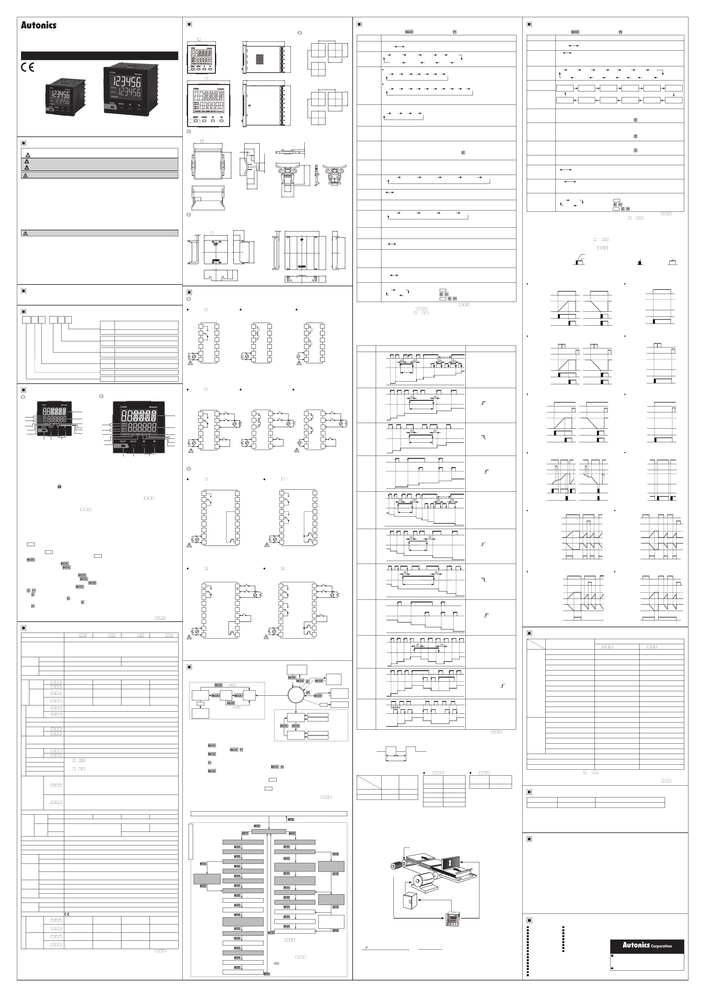
Unit Description
Specications
I N S T R U C T I O N M A N U A L
Thank you for choosing our Autonics product.
Please read the following safety considerations before use.
LCD Display Counter/Timer
CX SERIES
DRW171461AB
CX6S Series CX6M Series
1.
Fail-safe device must be installed when using the unit with machinery that may cause
serious injury or substantial economic loss. (e.g. nuclear power control, medical equipment,
ships, vehicles, railways, aircraft, combustion apparatus, safety equipment, crime/disaster
prevention devices, etc.)
Failure to follow this instruction may result in re, personal injury, or economic loss.
2. Install on a device panel to use.
Failure to follow this instruction may result in electric shock or re.
3. Do not connect, repair, or inspect the unit while connected to a power source.
Failure to follow this instruction may result in electric shock or re.
4. Check ‘Connections’ before wiring.
Failure to follow this instruction may result in re.
5. Do not disassemble or modify the unit.
Failure to follow this instruction may result in electric shock or re.
Safety Considerations
Dimensions
Warning
Caution
1. When connecting the power input and relay output, use AWG 20 (0.50mm2) cable or over,
and tighten the terminal screw with a tightening torque of 0.74 to 0.90N.m.
Failure to follow this instruction may result in re or malfunction due to contact failure.
2. Use the unit within the rated specications.
Failure to follow this instruction may result in re or product damage.
3. Use the unit within the rated specications.
Failure to follow this instruction may result in shortening the life cycle of the unit, or re.
4. Do not use the unit in the place where ammable/explosive/corrosive gas, humidity, direct
sunlight, radiant heat, vibration, impact, or salinity may be present.
Failure to follow this instruction may result in re or explosion.
5. Keep metal chip, dust, and wire residue from owing into the unit.
Failure to follow this instruction may result in re or product damage.
CX 1P
64 FS -
Power supply
Signal input method
Output
Size
Display digit
Item
No mark
Voltage input (PNP) /no-voltage input (NPN)
selectable type
FFree voltage input
224VAC 50/60Hz, 24-48VDC
4100-240VAC 50/60Hz
1P 1-stage setting
2P 2-stage setting
SDIN W48×H48mm
MDIN W72×H72mm
6999999 (6-digit)
CX LCD Display Counter/Timer
1. Counting value display component (red)
RUN mode
: Displays counting value for counter operation or time progress value for timer operation.
Function setting mode: Displays parameter.
2. Setting value display component (green)
RUN mode: Displays setting value.
Function setting mode: Displays parameter setting value.
3. Time unit indicator (h:m:s): Turns ON for time unit for timer.
4. Key lock indicator ( ): Turns ON for key lock setting.
5. Reset input indicator (RST): Turns ON for reset key input or reset signal input.
6. INH indicator (INH)
:
For the voltage input (PNP)/no-voltage input (NPN) selectable model (CX6 - ),
it turns ON for INHIBIT signal input.
(In case of CX6S Series and timer mode, it turns ON for INB/INH signal input.)
For free voltage input model (CX6 - F), it turns ON for INB/INH signal input for timer.
7. Output indicator (OUT1, OUT2): Turns ON for the dedicated control output ON.
8. SV checking and changing indicator (SET, SET1, SET2) (green)
: Turns ON when checking and changing SV.
9. COUNTER indicator (COUNTER): Turns ON for counter operation.
10. TOTAL indicator※1 (TOTAL)
: In case of TOTAL counter display mode, it turns ON with the COUNTER indicator.
11. TIMER indicator (TIMER)
: Flashes (progressing time) or Turns ON (stopping time) for timer operation.
12.
RESET
key
RUN mode, Function setting mode
: Press the
RESET
key to reset the counting value and turn OFF the output.
TOTAL counter display mode
※1
: Press the
RESET
key to reset the counting value of TOTAL counter.
13. key
RUN mode: Hold the key over 3 sec to enter function setting mode.
Press the key to select SV2 (SET2)/SV1 (SET1)/TOTAL counter※1 display for
counter operation.
Function setting mode: Hold the key over 3 sec to return RUN mode.
Press the key to save the SV and enter the next setting.
Function setting check mode: Hold the key over 1 sec to return RUN mode.
Changing SV mode: Press the key to save SV and return RUN mode.
14. , key
1) key
RUN mode: Press the key to change SV and move SV (SET, SET1, SET2) digits.
Changing SV mode: Press the key to change digits.
2) key
Changing SV mode: Increases SV.
Function setting mode: Changes the settings.
CX6S Series CX6M Series
※1: This is for the voltage input (PNP)/no-voltage input (NPN) selectable model (CX6 - ).
※1: This is for the voltage input (PNP)/no-voltage input (NPN) selectable model (CX6 - ).
※2: The weight includes packaging. The weight in parenthesis is for unit only.
※Environment resistance is rated at no freezing or condensation.
For the detail information and instructions, please refer to user manual and be sure to follow cautions.
Visit our homepage (www.autonics.com) to download manuals.
※
Please observe all safety considerations for safe and proper product operation to avoid hazards.
※ symbol represents caution due to special circumstances in which hazards may occur.
Warning Failure to follow these instructions may result in serious injury or death.
Caution Failure to follow these instructions may result in personal injury or product damage.
1
2
93
4
5
6
7
8
10
11
12 13 14
1
2
93
4
5
6
7
8
10
11
12 13 14
48 6 64.5
□44.8
72 6 64.5
□67.5
Bracket
Panel cut-out
Terminal cover (sold separately)
● CX6S Series
● CX6S Series
(RSA-COVER, 48×48mm)
● CX6M Series
● CX6M Series
(RMA-COVER, 72×72mm)
30.6
20
15
21
5
16
44.9
36
+0.2
-0.05
+0.3
0
45
48.6±0.2
+0.2
0
55
56
3.3
37.5
40.5
4
46
23.9
12
Min. 65
45
Min. 65
45
+0.6
0
+0.6
0
Min. 91
68
Min. 91
68
+0.7
0
+0.7
0
(unit: mm)
Connections
Operations
1. Voltage input (PNP)/no-voltage input (NPN) selectable model
CX6S-1P CX6S-2P4 CX6S-2P2
2. Free voltage input model
CX6S-1P F CX6S-2P2F CX6S-2P4F
CONTACT OUT
: 250VAC 3A, 30VDC 3A
RESISTIVE LOAD
SIGNAL INPUT
: 24-240VAC 50/60Hz, 24-240VDC
SOURCE: 100-240VAC 50/60Hz 4.2VA
24VAC 50/60Hz 3.6VA
24-48VDC 2.5W
INA
INB/INH
0VDC
RESET
1
2
3
4
7
10
8
511
9
612
※1
INPUT
OUT
CONTACT OUT1/OUT2
: 250VAC 3A, 30VDC 3A
RESISTIVE LOAD
SIGNAL INPUT
: 24-240VAC 50/60Hz, 24-240VDC
SOURCE: 100-240VAC 50/60Hz 4.9VA
0VDC
RESET
1
2
3
4
7
10
8
5 11
9
6 12
OUT2
OUT1
INB/INH
INA
INPUT
SOURCE:
100-240VAC 50/60Hz 6.4VA
24VAC 50/60Hz 5.5VA
24-48VDC 3.5W
CONTACT OUT:
250VAC 3A, 30VDC 3A
RESISTIVE LOAD
※1
INA
OUT INB/INH
12VDC 100mA
0VDC
RESET
TOTAL RESET
1
4
7
10
2
5
8
11
3
6
9
12
SOURCE:
100-240VAC 50/60Hz 6.7VA
CONTACT OUT1/OUT2:
250VAC 3A, 30VDC 3A
RESISTIVE LOAD
INA
OUT2
OUT1
INB/INH
12VDC 100mA
0VDC
RESET
TOTAL RESET
17
410
28
511
39
612
SOURCE:
24VAC 50/60Hz 5.6VA
24-48VDC 3.6W
CONTACT OUT1/OUT2:
250VAC 3A, 30VDC 3A
RESISTIVE LOAD
INA
OUT2
OUT1
0VDC
RESET
17
410
28
511
39
612
INB/INH
12VDC 100mA
TOTAL RESET
CONTACT OUT1/OUT2
: 250VAC 3A, 30VDC 3A
RESISTIVE LOAD
SIGNAL INPUT
: 24-240VAC 50/60Hz, 24-240VDC
SOURCE: 24VAC 50/60Hz 4.0VA
24-48VDC 2.8W
0VDC
RESET
1
2
3
4
7
10
8
5 11
9
6 12
OUT2
OUT1
INB/INH
INA
INPUT
CX6S Series
1. Voltage input (PNP)/no-voltage input (NPN) selectable model
CX6M-1P CX6M-2P
SOURCE: 100-240VAC 50/60Hz 7.1VA
24VAC 50/60Hz 6.2VA
24-48VDC 4W
CONTACT OUT:
250VAC 3A, 30VDC 3A RESISTIVE LOAD
INA
OUT INB
SOLID
STATE
OUT:
30VDC
100mA
0VDC
12VDC 100mA
RESET
INHIBIT
1
4
7
10
13
2
5
8
11
14
3
6
9
12
15
16
17
18
TOTAL RESET
※1
SOURCE: 100-240VAC 50/60Hz 7.5VA
24VAC 50/60Hz 6.3VA
24-48VDC 4.1W
CONTACT OUT1/OUT2:
250VAC 3A, 30VDC 3A RESISTIVE LOAD
OUT2
OUT1
OUT2
OUT1
INB
INA
SOLID
STATE
OUT:
30VDC
100mA
0VDC
12VDC 100mA
RESET
INHIBIT
TOTAL RESET
1
4
7
10
13
2
5
8
11
14
3
6
9
12
15
16
17
18
※1
2. Free voltage input model
CX6M-1P F CX6M-2P F
SOURCE: 100-240VAC 50/60Hz 5.4VA
24VAC 50/60Hz 4.5VA
24-48VDC 3.3W
CONTACT OUT1/OUT2: 250VAC 3A, 30VDC 3A
RESISTIVE LOAD
SIGNAL INPUT: 24-240VAC 50/60Hz, 24-240VDC
1
4
7
10
13
2
5
8
11
14
3
6
9
12
15
16
17
18
0VDC RESET
OUT2
OUT1
OUT1
OUT2
SIGNAL INPUT
INB/INH
INA
※1 SOLID
STATE
OUT:
30VDC
100mA
SOURCE: 100-240VAC 50/60Hz 4.7VA
24VAC 50/60Hz 3.9VA
24-48VDC 2.9W
CONTACT OUT: 250VAC 3A, 30VDC 3A
RESISTIVE LOAD
SIGNAL INPUT: 24-240VAC 50/60Hz, 24-240VDC
1
4
7
10
13
2
5
8
11
14
3
6
9
12
15
16
17
18
OUT
0VDC RESET
SIGNAL INPUT
INB/INH
INA
※1 SOLID
STATE
OUT:
30VDC
100mA
※1: AC voltage: 100-240VAC 50/60Hz
AC/DC voltage: 24VAC 50/60Hz, 24-48VDC
CX6M Series
1-1. Function setting mode
Hold the key over 3 sec to enter function setting mode in RUN mode.
Set the function by the , keys.
Hold the key over 3 sec to return RUN mode in function setting mode.
1-2. Function setting check mode
Hold the key over 1 sec to enter function setting check mode in RUN mode.
When checking the saved parameters, press the , key to check next item..
Hold the key over 1 sec at function setting check mode and it returns to RUN mode.
1-3. RESET
In RUN mode, function setting mode, press the
RESET
key to reset the current value and the output
turns OFF.
At TOTAL counter display mode※1, press the
RESET
key to reset TOTAL counter counting value and
the current counting value.
※1: This is for the voltage input (PNP)/no-voltage input (NPN) selectable model (CX6 - ).
TOTAL counter display mode is only for counter operation.
1. Operation and setting (counter/timer)
2. Function setting
1. Parameter setting
※1: For voltage input (PNP), no-voltage input (NPN) model (CX6 - ).
※2: For free voltage input model(CX6 - F), these parameters do not appear due to fixed setting.
※3: For 1-stage setting model (CX6 -1P ), OUT1 does not appear.
The OUT2 output time is displayed as OUtT.
※4: Decimal point and prescale decimal point
-Decimal point: Set the decimal point for display value regardless of prescale value.
-Prescale decimal point
: Set the decimal point for prescale value of counting value regardless of display value.
( key: Moves parameters, key: Changes parameter setting value)
Counter Mode
2. Input mode
3. Prescale function
Pulley
Cutter
Rotary encoder
Motor conlrol system
Motor
Counter
1. Parameter setting ( key: Moves parameters, key: Changes parameter setting value)
Timer Mode
※1: This is for the voltage input (PNP)/no-voltage input (NPN) selectable model (CX6 - ).
※2: INt2 mode is available only for 2-stage setting model(CX6 -2P ).
※3: When output mode is
OND, ONd1, ONd2, ONd3, FLk1, FLk2, INT, INt1, INt2, OFD, INTG,
TOTAL,
ONtD
, set time range [tRNG].
※4: When output mode is
FLK, NFD, NFD.1, set output ON TIME range [OnRNG] and output OFF
TIME
range [OFfRNG].
※5: In case of 1-stage setting model (CX6 -1P ), OUT1 output time does not appear.
OUT2 output time is displayed as OUtT.
※6: In case of free voltage input model (CX6 -
F), this parameter does not appear due to fixed
setting.
Model CX6S-1P CX6S-2P CX6M-1P CX6M-2P
Display digits 6-digit
Display method
7-segment (1st, 2nd digits of counting value display: white,
setting value display: green) LCD method,
11-segment (the other digits of counting value display: white) LCD method,
Operation display part: yellow LCD method
Character
size (W×H)
Counting value
4.1×10.1mm 6.2×15.2mm
Setting value
3.3×8.1mm 5×12.3mm
Power
supply
AC voltage
100-240VACᜠ 50/60Hz
AC/DC voltage
24VACᜠ 50/60Hz, 24-48VDCᜡ
Permissible voltage range 90 to 110% of rated voltage
Power
consumption
AC
voltage
CX6 - Max. 6.4VA Max. 6.7VA Max. 7.1VA Max. 7.5VA
CX6 - FMax. 4.2VA Max. 4.9VA Max. 4.7VA Max. 5.4VA
AC/DC
voltage
CX6 - AC: max. 5.5VA
DC: max. 3.5W
AC: max. 5.6VA
DC: max. 3.6W
AC: max. 6.2VA
DC: max. 4W
AC: max. 6.3VA
DC: max. 4.1W
CX6 - FAC: max. 3.6VA
DC: max. 2.5W
AC: max. 4.0VA
DC: max. 2.8W
AC: max. 3.9VA
DC: max. 2.9W
AC: max. 4.5VA
DC: max. 3.3W
Counter
Max. INA/INB
counting
speed
CX6 - Selectable among 1cps/30cps/300cps/1kcps/5kcps
CX6 - F 20cps
Counting range -99999 to 999999
Scale Decimal point up to fth digit
Min. signal
width
CX6 - RESET, TOTAL RESET signal: selectable among 1ms/20ms
CX6 - FRESET signal: 25ms
Timer
Time range 999.999s, 9999.99s, 99999.9s, 999999s, 99m59.99s, 999m59.9s,
9999m59s, 99999.9m, 999999m, 99h59m59s, 9999h59m, 99999.9h
Operation mode Up, Down
Min. signal
width
CX6 -
INA, INHIBIT, RESET, TOTAL RESET signal: selectable among 1ms/20ms
CX6 - FINA, INH, RESET signal: 25ms
Repeat error [CX6 - ]-In case of power ON start: max. ±0.01% ±0.05s
In case of signal ON start: max. ±0.01% ±0.03s
[CX6 - F]-In case of power ON start: max. ±0.01% ±0.08s
In case of signal ON start: max. ±0.01% ±0.06s
Set error
Voltage error
Temp. error
Input
method
CX6 -
Selectable among voltage input (PNP)/no-voltage input (NPN)
[Voltage input (PNP)]-input impedance: 10.8kΩ,
[H]: 5-30VDCᜡ, [L]: 0-2VDC
[No-voltage input (NPN)]-short-circuit impedance: max. 1kΩ,
short-circuit residual voltage: max. 2VDC
CX6 - F
[Free voltage input]-INA (START) , INB (INHIBIT) input
[H]: 24-240VDCᜡ/24-240VACᜠ 50/60Hz, [L]: 0-10VDC/VAC
[No-voltage input]- RESET input, short-circuit impedance: max. 1kΩ,
short-circuit residual voltage: max. 2V
One-shot output time 0.01 to 99.99s setting
Control
output
Contact Type SPDT (1c): 1 SPST (1a): 2 SPDT (1c): 1 SPDT (1c): 2
Capacity Max. 250VACᜠ 3A, 30VDCᜡ 3A resistive load
Solid
state
Typ e
-
NPN open
collector: 1
NPN open
collector: 2
Capacity Max. 30VDCᜡ 100mA
External power supply※1Max. 12VDCᜡ ±10%, 100mA
Memory retention Approx. 10 years (non-volatile memory)
Insulation resistance Over 100MΩ (at 500VDC megger)
Dielectric strength 3,000VAC 50/60Hz for 1 min
Noise
immunity
AC voltage Square-wave noise by noise simulator (pulse width 1㎲) ±2kV
AC/DC voltage Square-wave noise by noise simulator (pulse width 1㎲) ±500V
Vibration
Mechanical 0.75mm amplitude at frequency 10 to 55Hz (for 1 min) in each X, Y, Z
direction for 1 hour
Malfunction 0.5mm amplitude at frequency 10 to 55Hz (for 1 min) in each X, Y, Z
direction for 10 minutes
Shock Mechanical 300m/s² (approx. 30G) in each X, Y, Z direction for 3 times
Malfunction 100m/s² (approx. 10G) in each X, Y, Z direction for 3 times
Relay life
cycle
Mechanical Min. 5,000,000 operations
Malfunction Min. 100,000 operations
Protection structure Front part: IP50 (IEC standard)
Environ-
ment
Ambient temp. -10 to 55℃, storage: -25 to 65℃
Ambient humi. 35 to 85%RH, storage: 35 to 85%RH
Approval
Weight※2
AC
voltage
CX6 - Approx. 157g
(approx. 112g)
Approx. 162g
(approx. 117g)
Approx. 235g
(approx. 170g)
Approx. 240g
(approx. 175g)
CX6 - FApprox. 155g
(approx. 110g)
Approx. 160g
(approx. 115g)
Approx. 233g
(approx. 168g)
Approx. 238g
(approx. 173g)
AC/DC
voltage
CX6 - Approx. 156g
(approx. 111g)
Approx. 161g
(approx. 116g)
Approx. 234g
(approx. 169g)
Approx. 239g
(approx. 174g)
CX6 - FApprox. 154g
(approx. 109g)
Approx. 159g
(approx. 114g)
Approx. 232g
(approx. 167g)
Approx. 237g
(approx. 172g)
※
The above specications are subject to change and some models may be discontinued
without notice.
※Be sure to follow cautions written in the instruction manual, user manual and the technical
descriptions (catalog, homepage).
TOTAL
counter
Reset
TOTAL
counter
RUN mode
Changing
SV
mode
Function
setting
check mode
Function
setting mode
SET 2
value
SET 1
value
3 sec
3 sec
1 sec
1 sec
PV RESET
(RUN mode)
(RUN mode)
OUT 1
OUT 2
SET 2 TIMER
12:30:25
1:25:47
TIMER
12:34:56
5:43:50
OUT 1
OUT 2
SET 1
Display PV
Display PV
Display SET 2
Display SET 1
[Counter]
[Timer]
(CX6 - )
(CX6 - F)
RESET RESET
RUN mode
(
In case of
FLK,
NFD, NFdI)
(In case of OND, ONdI,
ONd2, ONd3, FLk1,
FLk2, INT, INt1,
INt2, OFD, INTG,
TOTAL※1, ONtD)
3 sec
Min. reset time※1 [
R
ESET
]
Input logic※1 [SIG]Input logic※1 [SIG]
TOTAL counter※2 [
T
OTAL
]
Input signal time※1 [
IN-T
]
Memory protection [
DATA
]
Key lock [LOCK]
Key lock [LOCK]
Counter/Timer [C-T]
Input mode [InM]Up/Down mode [U-D]
Output mode [OUtM]Output mode [OUtM]
Max. counting speed
※1
[
CPS
]
OUT 2 output time [
OUT2
]
OUT 2 output time [
OUT2
]
OUT 1 output time [
OUT1
]
OUT 1 output time [
OUT1
]
Decimal point [DP]
Prescale value [SCL]
Start point value [
S
TART
]
Prescale decimal point
[
S
ClDP]
Output ON
time range [
O
nRNG]
Output OFF
time range [
OF
fRNG]
Counter [COUNT] Timer [TIMEㅅㅅ]
3 sec
※: When changing the setting of shaded
parameters, all output turn OFF.
When returning RUN mode, PV is reset.
※1: In case of free voltage input model
(CX6 -
F), these parameters do not
appear due to fixed setting.
※2:This parameter is for the voltage input
(PNP)/no-voltage input (NPN) selectable
model (CX6 - ).
(2-stage
output
model)
(1-stage
output
model)
OUT output time
[OUtT]
Time range
[tRNG]
OUT output time
[OUtT]
Function setting mode
Memory protec-
tion※2 [
DATA
]
Parameter Parameter setting value
Counter/Timer
[C-T]COUNT TIME ※COUNT: Counter
TIME: Timer
Input mode
[InM]
UP
UD-C※1 UD-B※1 UD-A DN-3 DN-2
DN-1DNUP-1 UP-3UP-2
Output mode
[OUtM]
Input mode is UP, UP-1, UP-2, UP-3 or DN, DN-1, DN-2, DN-3,
F PKN R[ Q A
Input mode is UD-A, UD-B※1, UD-C※1
F PKN R[ Q A S T D
※ If max. counting speed is 5kcps, and output mode is D, max. counting speed is
automatically changed as 30cps, factory default.
Max. counting
speed※2 [CPS]
30 1300 5K1K
※ Max. counting speed is when duty ratio of INA or
INB input signal is 1:1.
It is applied for INA, or INB input as same.
※ When output mode is D, set max. counting speed
one among 1cps, 30cps, 300cps, or 1kcps.
OUT 2
output time※3
[OUT2]
※Set one-shot output time of OUT 2.
※Setting range: 00.01 to 99.99 sec
※
When output mode is F, N, S, T, D, this parameter does not appear. (xed as HOLD)
OUT 1
output time※3
[OUT1]
※Set one-shot output time of OUT 1.
※Setting range: 00.01 to 99.99 sec, Hold
※When number of tens digit is ashing, press the key once and HOLD appears.
※When output mode is S, T, D, this parameter does not appear. (xed as HOLD)
OUT
output time※3
[OUtT]
※Setting range: 00.01 to 99.99 sec
※
When output mode is F, N, S, T, D, this parameter does not appear. (xed as HOLD)
Decimal point
※
4
[DP]
------ --.---- -.----------.- ---.-------.--
※Decimal point is applied to PV and SV.
Min. reset time※2
[RESET]
1 20, unit: ms
※Set min. width of external reset signal input.
Input logic※2
[SIG]NPN: No-voltage input, PNP: Voltage input
Prescale
decimal point※4
[SClDP]
-.----- --.---------.- ---.-------.--
※Decimal point of prescale should not set smaller than decimal point [DP].
Prescale
value [SCL]
※Setting range: 0.00001 to 99999.9
※Setting range of prescale is linked with prescale decimal point [SClDP] setting.
TOTAL counter
※1
[TOTAL]ㅅㅅON OFF
Start point
value
[START]
※
Setting range of start point value is linked with decimal point [DP] setting.
(0.00000 to 999999)
※WheninputmodeisDN, DN-1, DN-2, this parameter doesnotappear.
※
WhentotalcountfunctionisON,
thisparameter
does not appear.
※1
Memory
protection
[DATA]
CLR REC
※CLR: Resets the counting value when power OFF.
REC: Maintains the counting value when power OFF.
(memory protection)
Key lock
[LOCK]
lOFF LOc1
LOc3 LOc2
※lOFF: Unlock keys, key lock indicator turns OFF
LOc1: Locks
RESET
key, key lock indicator turns ON
LOc2: Locks , keys, key lock indicator turns ON
LOc3: Locks
RESET
, , keys, key lock indicator turns ON
Input mode
Counting chart Operation
Up
[UP]
INA H
L
No counting
No counting
0
1234567
H
L
INB
Count
※ When INA is counting input,
INB is no counting input.
When INB is counting input,
INA is no counting input.
Up-1
[UP-1]
INA H
L
No counting
0
123
45
H
L
INB
Count
※ When INA input signal is
rising ( ) , it counts.
※INA: Counting input
※INB: No counting input
Up-2
[UP-2]
INA H
L
No counting
0
123
4
H
L
INB
Count
※ When INA input signal is
falling ( ) , it counts.
※INA: Counting input
※INB: No counting input
Up-3
[UP-3]
INA H
L
0
12356
H
L
INB
Count
※ When INA or INB input signal
is rising ( ) , it counts.
※INA: Counting input
※INB: Counting input
Down
[DN]
INA H
L
No counting
No counting
0
n
n-1
n-2
n-3
n-4
n-5 n-6
n-7
H
L
INB
Count
※ When INA is counting input,
INB is no counting input.
When INB is counting input,
INA is no counting input.
Down-1
[DN-1]
INA H
L
No counting
0
n
n-1 n-2 n-3 n-4 n-5
H
L
INB
Count
※ When INA input signal is
rising ( ) , it counts.
※INA: Counting input
※INB: No counting input
Down-2
[DN-2]
INA H
L
No counting
0
n
n-1
n-2 n-3 n-4 n-5
H
L
INB
Count
※ When INA input signal is
falling ( ) , it counts.
※INA: Counting input
※INB: No counting input
Down-3
[DN-3]
INA H
L
0
n
n-1
n-2 n-3 n-5 n-6
H
L
INB
Count
※ When INA or INB input signal
is rising ( ) , it counts.
※INA: Counting input
※INB: Counting input
Up/Down-A
[UD-A]
INA H
L
0
12
34321234
H
L
INB
Count
※INA: Counting input
INB: Counting command input
※
When INB is "L",
counting command is up.
When INB is "H",
counting command is down.
Up/Down-B
※1
[UD-B]
INA H
L
0
123
4
32 2 34
H
L
INB
Count
※INA: Up counting input
INB: Down counting input
※When INA and INB input
signals are rising ( ) at
the same time, it maintains
previous counting value.
Up/Down-C
※1
[UD-C]
INA H
L
0
1
1
22
2
33
H
L
INB
Count
※ When connecting encoder
output A, B phase with
counter input, INA, INB, set
input mode [InM] as phase
different input [UD-C] for
counter operation.
※The meaning of "H", "L"
Input
method
Character
Voltage
input
(PNP)
No-voltage
input
(NPN)
H 5-30VDC Short
L 0-2VDC Open
INA
(INB) ON
T.on
TT.on, T.off: Min. signal width
T.off
ONOFF OFF
H
L
CX6 - CX6 - F
※Min. signal width by counting speed
Counting
speed
Min. signal
width
1cps 500ms
30cps 16.7ms
300cps 1.67ms
1kcps 0.5ms
5kcps 0.1ms
Counting
speed
Min. signal
width
20cps 25ms
※1: This is for the voltage input (PNP)/no-voltage input (NPN) selectable model (CX6 - ).
※ A: over min. signal width, B: over than 1/2 of min. signal width.
If the signal is smaller than these width, it may cause counting error (±1).
This function is to set and display calculated unit for actual length, liquid, position, etc. It is called
“prescale value” for measured length, liquid, or position, etc per 1 pulse. For example, when moving L,
the desired length to be measured, and P, the number of pulses per 1 revolution of a rotary encoder,
occurs, prescale value is L/P.
Set decimal point [DP] as [-----.-], prescale decimal point [SClDP] as [---.---], and prescale
value [SCL] as [)069] at function setting mode.
It is available to control conveyor position by 0.1mm unit.
E.g.) Positioning control by counter and encoder
=0.069mm/pulse
[ Diameter (D) of pulley connected with encoder=22mm, the number of pulses by 1 rotation of
encoder=1,000]
*Prescale value
= × Diameter (D) of pulley
The number of pulses by 1
rotation of encoder
=3.1416 × 22
1000
Parameter Parameter setting value
Counter/Timer
[C-T]COUNT TIME ※COUNT: Counter
TIME: Timer
Up/Down mode
[U-D]
UP DN
※UP: Time progresses from '0' to the setting time.
DN: Time progresses from the setting time to '0'.
Output mode
[OUtM]
OND
TOTAL※1
ONtD INTG NFd1 NFD OFD INt2※2 INt1
FLk1 FLk2 INTFLKONd1 ONd3ONd2
Time range
[tRNG]※3
TIMER s
999.999
TIMER s
9999.99
TIMER s
99999.9
TIMER m
99999.9
TIMER h
99999.9
TIMER m
999999
TIMER m:s
99:59.99
TIMER h:m:s
99:59:59
TIMER m:s
999:59.9
TIMER m:s
9999:59
TIMER h:m
9999:59
TIMER s
999999
output ON TIME
range [OnRNG]
※4
,
output OFF TIME
range [OFfRNG]
※4
OUT 2 output
time※5
[OUT2]
※Set one-shot output time of OUT 2.
※Setting range: 00.01 to 99.99 sec, Hold
※
When number of tens digit is ashing, press the key once and HOLD appears.
OUT 1 output
time※5
[OUT1]
※
Set one-shot output time of OUT 1.
※
Setting range: 00.01 to 99.99 sec, Hold
※
When number of tens digit is ashing, press the key once and HOLD appears.
OUT output
time※5
[OUtT]
※
Setting range: 00.01 to 99.99 sec, Hold
※
When number of tens digit is ashing, press the key once and HOLD appears.
Input logic※6
[SIG]NPN: No-voltage input, PNP: Voltage input
Input signal
time※6
[IN-T]
1 20, unit: ms
※Set min. width of INA, INHIBIT, RESET, TOTAL RESET signal
Memory
protection
[DATA]
CLR REC
※CLR: Resets the counting value when power OFF.
REC: Maintains the counting value when power OFF. (memory protection)
Key lock
[LOCK]
lOFF LOc1
LOc3 LOc2
※lOFF: Unlock keys, key lock indicator turns OFF
LOc1: Locks
RESET
key, key lock indicator turns ON
LOc2: Locks , keys, key lock indicator turns ON
LOc3:
Locks
RESET
, , keys, key lock indicator turns ON
1. Follow instructions in ‘Cautions during Use’. Otherwise, it may cause unexpected accidents.
2. In case of 24-48VDC, 24VAC model, power supply should be insulated and limited voltage/
current or Class 2, SELV power supply device.
3. Use the product, 0.1 sec after supplying power.
4. When supplying or turning off the power, use a switch or etc. to avoid chattering.
5. Install a power switch or circuit breaker in the easily accessible place for supplying or
disconnecting the power.
6. Keep away from high voltage lines or power lines to prevent inductive noise.
In case installing power line and input signal line closely, use line lter or varistor at power line
and shielded wire at input signal line.
Do not use near the equipment which generates strong magnetic force or high frequency noise.
7. This unit may be used in the following environments.
①Indoors (in the environment condition rated in ‘Specications’)
②Altitude max. 2,000m
③Pollution degree 2
④Installation category II
B. OND.1 (Signal ON Delay 1) mode [ONd1]
C. OND.2 (Power ON Delay) mode [ONd2]
E. NFD (ON-OFF Delay) mode [NFD]
F. NFD.1 (ON-OFF Delay1) mode [NFd1]
Set ‘0’ for setting time 1.
Set ‘0’ for setting time 1.
Set '0' for Off_Delay setting time.
Set ‘0’ for Off_Delay setting time.
Set ‘0’ for setting time 2.
Set ‘0’ for setting time 2.
Set ‘0’ for On_Delay setting time.
Set ‘0’ for On_Delay setting time.
INA (START)
RESET
Setting time 1
0
OUT 1
OUT 2
Up mode
POWER
RESET
Setting time 2
0
OUT 1
OUT 2
Down mode Up mode
POWER
RESET
Setting time 1
0
OUT 1
OUT 2
INA (START)
UP
DISPLAY
DOWN
RESET
On_Delay
On_Delay
0
0
OUT 2
(OUT)
INA (START)
UP
DISPLAY
DOWN
RESET
Off_Delay
Off_Delay
0
0
OUT 2
(OUT)
INA (START)
UP
DISPLAY
DOWN
RESET
On_Delay
On_Delay
0
0
OUT 2
(OUT)
INA (START)
UP
DISPLAY
DOWN
RESET
Off_Delay
Off_Delay
0
0
OUT 2
(OUT)
2. Timer '0' time setting
2-1. Timer output mode for '0' time setting [OND, ONd1, ONd2, ONd3, NFD, NFd1]
2-2. Operations by output mode ('0' time setting)
A. OND (Signal ON Delay) mode [OND]
Set '0' for setting time 1. Set ‘0’ for setting time 2.
INA (START)
Setting time 1
0
OUT 1
OUT 2
Up mode
INA (START)
Setting time 2
0
OUT 1
OUT 2
Down mode
※1: For 1-stage setting model (CX6 -1P ), OUT1 does not appear.
The output time of OUT2 is displayed as OUtT.
※2: This is for the voltage input (PNP)/no-voltage input (NPN) selectable model (CX6 - ).
Cautions during Use
Error Display and Output Operation
Factory Default
Up mode
INA (START)
RESET
Setting time 2
0
OUT 1
OUT 2
Down mode
Major Products
One-shot output (0.01 to 99.99 sec) One-shot output Retained output
Retained output
Photoelectric Sensors Temperature Controllers
Fiber Optic Sensors Temperature/Humidity Transducers
Door Sensors SSR/Power Controllers
Door Side Sensors Counters
Area Sensors Timers
Proximity Sensors Panel Meters
Pressure Sensors Tachometer/Pulse (Rate) Meters
Rotary Encoders Display Units
Connector/Sockets Sensor Controllers
Switching Mode Power Supplies
Control Switches/Lamps/Buzzers
I/O Terminal Blocks & Cables
Stepper Motors/Drivers/Motion Controllers
Graphic/Logic Panels
Field Network Devices
Laser Marking System (Fiber, Co₂, Nd: YAG)
Laser Welding/Cutting System
http://www.autonics.com
HEADQUARTERS:
18, Bansong-ro 513 beon-gil, Haeundae-gu, Busan, South
Korea, 48002
TEL: 82-51-519-3232
DRW171461AB
Parameter Factory default
CX6 - CX6 - F
Counter
InM UD-C UD-A
OUtMF F
CPS 30
-
OUT2 (OUtT※1)HOLD (xed) HOLD (xed)
OUT1※10)10 0)10
DP ------ ------
RESET 20ms
-
SIG NPN
-
SClDP -.-----, -.-----,
SCL !00000 !00000
TOTAL※2OFF
-
START 000000 000000
DATA CLR CLR
Timer
U-D UP UP
OUtMOND OND
OUT2 (OUtT※1)HOLD HOLD
OUT1※10)10 0)10
tRNG 99(999s99(999s
SIG※2NPN
-
IN-T 20ms
-
LOCK lOFF lOFF
SET1 1000 1000
SET2 5000 5000
※When error occurs, the output turns OFF.
※
When 1st setting value is set as 0 (zero), OUT1 maintains OFF.
When 2nd setting value is smaller than 1st setting value, 1st setting value is ignored and only
OUT2 output operates.
※Indicator model does not have error display function.
Error Display Error description Troubleshooting
ERR0 Setting value is 0. Change the setting value anything but 0.
D. OND.3 (Power ON Delay) mode [ONd3]
Set ‘0’ for setting time 1. Set ‘0’ for setting time 2.
Up mode
POWER
RESET
Setting time 2
0
OUT1
OUT2
Down mode Up mode
POWER
RESET
Setting time 1
0
OUT1
OUT2
410
70
68.5
64
13
3 48.4 13
22
45
41
18
22
