

CONTENTS
Safety precautions………………………………………………………………………..…
Alignment instructions …………………………….…….…………………………………
Method of software upgrading……………………………………………………………..
Working principle analysis of the unit……………………………….………….………….
Block diagram…………………………………..………………………………….…………
IC block diagram………………………………………………………………………..……
Wiring diagram …………………………………………………………………………….
Troubleshooting guide ………………………………………………………………..……
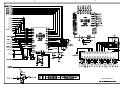
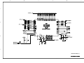
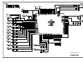
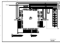
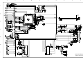
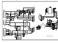
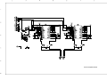
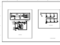
Schematic diagram…………………………………………………………………………
APPENDIX-A: Assembly list
APPENDIX-B: Exploded View
1
3
8
10
11
12
15
26
22
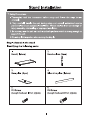
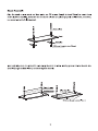
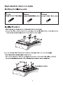
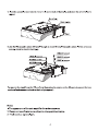
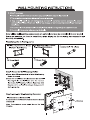
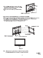
Stand installation
Wall mounting instructions

1
Safety Precautions
Please read the “Points for attention for the Maintenance & Repair of PDP” and “Criterion for
Identifying the Defects on Screen” as below, before inspecting and adjusting the TV set.
1. “Points for attention for the Maintenance & Repair of PDP”
To avoid possible danger, damage or jeopardy to health and to prevent PDP screen from new
damage, the maintenance people must read the following carefully. If they ignore the following
warnings, there will be deathful risks:
1.1 Screens vary from one model to another and therefore not interchangeable. Be sure to use
the same type of screen in the replacement.
1.2 The operation voltage is approximately 350V for PDP module (including screen, driving
circuit, logic circuit and power module). If you want to conduct maintenance work on PDP
module when the set is in normal operation or just after the power is off, you must take proper
measures to avoid electric shock and never have direct contact or touch with the circuitry of the
working module or metal parts. That’s because within a short time relatively high voltage still
remains on the capacitor of the driving part even after the power is off. Make sure to begin
relevant maintenance operation at least one minute after the power is off.
1.3 Don’t apply on the module any power supply that is higher than the specification. If the
power supply used deviates from the value given in the specification, there might be a
possibility of leading to fire or damage to the module.
1.4 Never have operation or mounting work under unsuitable environment such as areas in the
vicinity of water – bathroom, laundry, water chute of kitchen – sources of fire, heat-radiation
parts or direct exposure to sunlight. Otherwise there will be kickbacks.
1.5 In case foreign substances such as water, liquid, metal slices or others fall into the module
carelessly power must be cut off immediately. Keep the module as it is and do not move
anything on the module. Otherwise it might be possible to contact the high voltage or cause
shock short circuit so that it may lead to fire or electric shock.
1.6 If there is smoke, abnormal smell or sound from the module, please cut the power off
immediately. Likewise in case the screen doesn’t work when the power is on or during the
operation, please also cut off the power at once. No more operation in this case.
1.7 Do not remove or plug its connection wire when the module is in operation or right after the
power is off. That’s because there remains a relatively high voltage on the capacitor of the
driving circuit. If there is a need to remove or plug in the connection wire, please wait at least
one minute after the power is off.
1.8 Considering the module has a glass faceplate, please avoid extrusion by external force lest
it should cause glass breakage that may get people injured. Two people are needed in
cooperation to move this module lest contingency takes place.
1.9 The complete TV set is designed on the basis of full consideration of thermal dissipation by
convection, with the round hole on the top for heat emission. To avoid overheat, please do not
have any covering on the hole during normal operation and never put it in the place where the
space is narrow and in bad ventilation.
1.10 There is quite a number of circuits in PDP that are integrated ones. Please be on guard
Note: This maintenance manual is intended only for the reference of the maintenance people.
Please pay attention to the following points before carrying out the maintenance work.

2
against static electricity. During maintenance operation be sure to cover yourself with anti-static
bag and before operation make sure to have it sufficiently grounded.
1.11 There are a big number of connection wires distributed around the screen. Please take
care not to touch or scuff them during maintenance or removing the screen, because once they
are damaged the screen will fail to work and it’s not possible to repair it.
If the connection wires, connectors or components fixed by the thermotropic glue need to
disengage when service, please soak the thermotropic glue into the alcohol and then pull them
out in case of damage.
1.12 Connector for the circuit board of the screen part is relatively fine and delicate. Please
take care in the replacement operation lest it should get damaged.
1.13 Special care must be taken during transportation and handling because strenuous
vibration could lead to screen glass breakage or damage on the driving circuitry. Be sure to use
a strong outer case to pack it up before transportation or handling.
1.14 Please put it for storage in an environment in which the conditions are under control so as
to prevent the temperature and humidity from exceeding the scope stipulated in the
specification. For prolonged storage please cover it with anti-moisture bag and have them piled
and stored in one place. The environmental conditions are tabulated as below:
Temperature Scope for operation 0~50centigrade
Scope for storage -15~60centigrade
Humidity Scope for operation 20%~80%
Scope for storage 20%~80%
1.15 If a fixed picture is displayed for a long time, difference in its brightness and color may
occur compared with movable pictures. But it doesn’t show any problem and the reason is that
there is reduced density of fluorescent powder in the former. On the other hand, even if
changes take place in the picture, it can keep its brightness for a period of time (several
minutes). It’s a feature inherent with plasma and it’s not abnormal. However please try as much
as possible to avoid showing a still picture of high brightness for a long time during operation.
1.16 As a digitalized display devise, this module is provided with error diffusion technology and
the gray scale and false enhancement of contour can be displayed by reusing of sub-field. As
compared with cathode ray tube, it can be found in the moving picture that at the brim of the
face of a person there are some wrong colors.
1.17 During the display of graph (indicating the gradual change in brightness horizontally or
vertically) resulting from gray scale test it can be found that the brightness for the two adjacent
levels is uneven. This is caused by the reuse of sub-field, the display of load rectification and
the electrolysis.
1.18 The screen front plate is of glass. Please make sure that the screen has been put in place
during erection. If it is not in place before the erection begins it may lead to screen crack or
breakage.
1.19 Make sure the screw used in the mounting of the screen is of the original specs lest it
should cause damage to the screen due to mismatch. Special care should be taken not to use
too long or too big screw.
1.20 Care must be taken to guard against dust during assembling or dismantling, especially to
avoid dirt from falling in between the screen and the glass lest it should harm the receiving and

3
viewing effect.
1.21 There is piece of insulator stuck on the rear chassis corresponding to the power supply
board. It is used to isolate the cool part from the hot part. Please take care to keep it intact lest
it should become a potential safety trouble.
1.22 In addition to plasma screen, the glass is a part of high value. It has such functions as
anti-radiation, adjustment of color temperature etc. Please handle it carefully.
Alignment instructions
1. Alignment equipment
PM5515 (video signal generator)
VG-848/VG-849 (YUV,VGA,DVI/HDMI signal generator)
CA100 (white balancer)
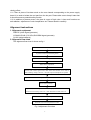
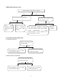
2. Alignment flow-chart
The alignment flow-chart is shown as fig-1
Fig-1 adjustment flow-chart
Check if DDC and FLASH are flash written
To produce main board and analog board
All testing
White balance adjustment
Connect with central signal source, then check each function of TV such as
station leaking, analog control etc., check the output of headphone and speaker
Input AV/SVIDEO and HD signal, then check each function of all the terminals
Input VGA, HDMI signal, check if the display is normal, check eac
h
function such as analog control etc., check horizontal /vertical center etc.
Preset ex-factory
Check the accessories and pack them in box
Check RS232 function.

4
3. Adjusting instruction
3.1 Unit adjustments
Connect all the boards according the wiring diagram, then power on and check if the display is
normal.
The method for using factory menu
The first press the “source” button, then press the “2580“ buttons enter factory menu. Press the
“SLEEP” button to select the adjustment page menu, press ▲and ▼to select item, press ◄and
► to adjust the value, press “MENU” button to exit the factory menu. If the unit does not turn off,
you can press the “SLEEP” button to enter factory menu again. Turn off the unit to exit the
factory menu.
3.2 EEPROM initialization
Enter page one of the factory menu, select the EEPROM INITIALIZE to ON, turn off the unit
then turn on again.
Note: it needs a little long time to display the LOGO after turn on again.
3.3 White balance adjustment
The 16 level gray-scale signal (DVI:TIMING978 PATTAN921, HDMI:TIMING853, PATTERN992)
sends to DVI/HDMI channel from VG-848/VG-849, enter the user menu and set color to 0, then
enter the factory menu white balance adjustment page. Select the normal color temperature
item, fixed GGAIN to be 128, adjust B, RGIAN to let the third color coordinate on the right be
(280, 290); fixed the GOFFSET to be 128H, adjust B, ROFFSET to let the third color coordinate
on the left be (280,290) at 5 nits.
Select the cool color temperature, adjust the color coordinate be (270, 283)
Select the warm color temperature, adjust the color coordinate be (300, 320)
After adjustment, switch to AV, VGA and YPbPr and have a check. If there is some deviation in
some channel, please adjust it independently.
Note: after adjust the white balance in HDMI, it will store the data to other channels.
4 Performance check
4.1 TV function
Connect RF-TV terminal to the central signal source and enter the setting menu, set the
country category, then enter the search menu → auto search, , check if there is station skipping.
Check the manual search, fine turning, the output of speaker and earphone and picture. Open
the PIP and POP modes, connect the earphone and check the display and sound.
4.2 AV/S-video input terminal
Input AV/S signal, check if the picture and sound is normal. Open the PIP and POP modes,
connect the earphone and check the display and sound.
4.3 YPbPr /YCbCr terminal
Input the YUV signal (VG-848 signal generator), separate input YUV format signal of table 1,
check if the image and sound is normal. If the image is deflection of the H-field, select auto
sync correction of the SCREEN menu. If the image is slight disturb, adjust the FINE TUNE
correction of the SCREEN menu. Open the PIP mode, connect the earphone, and check if the
image and sound is normal.

5
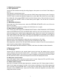
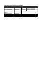
Table 1 YUV format signal
No H-frequency (KHz) V-frequency (KHz) Signal
1
15.734 59.94 SDTV 480i
2
31.469 59.94 HDTV 480p
3
44.955 59.94 HDTV 720p
4
33.716 59.94 HDTV 1080i
5
67.5 60 HDTV 1080P
6
15.625 50 SDTV 576i
7
31.25 50 HDTV 576p
8
37.5 50 HDTV 720p
9
33.75 50 HDTV 1080i
10
56.25 50 HDTV 1080P
4.4 VGA terminal
Input the VGA signal (VG-848 signal generator), separate input VGA format signal of table 2,
check if the image and sound is normal. If the image is deflection of the H-field, select auto
sync correction of the SCREEN menu. If the image is slight disturb, adjust the FINE TUNE
correction of the SCREEN menu. Open the PIP mode, connect the earphone, and check if the
image and sound is normal.
4.5 HDMI terminal
HDMI signal format receive the three high definition signal: 480P, 576P, 720P/50/60Hz,
1080I/50/60Hz, 1080P/50/60Hz except for the table 2 signal. Check if the image (contain
HDCP ON and OFF) and sound is normal (use VG-849 generator). If the image is deflection of
the H-field, perform manual correction according the SCREEN menu. Open the PIP mode,
connect the earphone, and check if the image and sound is normal. Input DVI audio signal and
check if it is normal.
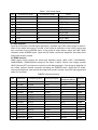
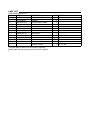
TABLE2 VGA signal format
No Resolution H-frequency(kHz) V-frenquency(Hz)
Point clock pulse
frenquency(MHz)
Remark
1 720x400 31.469 70.086 28.322 IBM
2
640x480 31.469 59.94 25.175 IBM
3 640x480 37.861 72.809 31.5 VESA
4 640x480 37.5 75 31.5 VESA
5
640x480 43.269 85.008 36 VESA
6 800x600 35.156 56.25 36 VESA
7
800x600 37.879 60.317 40 VESA
8 800x600 48.077 72.188 50 VESA
9
800x600 46.875 75 49.5 VESA
10 800x600 53.674 85.061 56.25 VESA
11
1024x768 48.363 60.004 65 VESA
12 1024x768 56.476 70.069 75 VESA
13 1024x768 60.023 75.029 78.75 VESA
14 1024x768 68.667 84.98 94.486 VESA
15 1280x1024 63.98 60.02 108.00 VESA

6
4.6 Clock function
Enter user menu clock setting item, set the clock and calendar then power off, power on again
and check if the clock and calendar is stored.
4.7 RS232 function
Connect to RS232 port of PC, check if the control is normal.
4.8 Ex-factory setting of user menu
1) select TV channel
2) picture menu, Mode: Standard, color temperature: nature
3) sound menu, Volume: 20, Balance: 00, Earphone volume:20, Mode: music, BBE: off, AVC:
off
4) image menu, Mode: Auto
5) channel menu, Color mode: Auto, Sound mode: DK
6) setup menu, Child Lock: Off, Menu Language: English, OSD transparency :7, OSD time out:
15s, Blue Screen: On.
Note: the 4) and 5) items should be set according to clients require. The user menu may be
different depending on the clients.
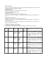
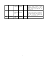
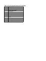
5. Method for software flash-written
Some chips should be flash-written first then be paste, the method is shown in talbe3.
No. Code Type Function
Written
before
paste
Method
NA01 5272402002 IC_AT24C
02BN10S
U-1.8
First road
HDMI
EDID
Yes
Program code 568HW0002B, instrument
ALL-100, “select factory”: ATMEL/Serial
EPROM/type AT24C02, click “Run’ to load
the program, select “Binary”, “FF”, then
press “OK”.
NA02 5272402002 IC_AT24C
02BN10S
U-1.8
Second
road
HDMI
EDID
Yes
Program code 568HW0006H, instrument
ALL-100, “select factory”: ATMEL/Serial
EPROM/type AT24C02, click “Run’ to load
the program, select “Binary”, “FF”, then
press “OK”.
NA03 5272402002 IC_AT24C
02BN10S
U-1.8
Third road
HDMI
EDID
Yes
Program code 568HW0006I, instrument
ALL-100, “select factory”: ATMEL/Serial
EPROM/type AT24C02, click “Run’ to load
the program, select “Binary”, “FF”, then
press “OK”.
NB02 5272421001 IC_24LCS
21A/SN
VGA EDID Yes
Program code 568HW0003C, instrument
ALL-100, “select factory”: ATMEL/Serial
EPROM/type AT24C21, click “Run’ to load
the program, select “Binary”, “FF”, then
press “OK”.

7
N601 5270915001 IC_P89LP
C915FDH
Power
manage
IC
Yes
Program code 568HW0017D, instrument
ALL-100, “select factory”: PHILIPS
/MPU/MCU/type 89LPC915, click “Run’ to
load the program, select “intel HEX”, “FF”,
then press “OK”.
N802 5272900801 IC_S29AL
008D70TF
I020
Main CPU
program
Yes
Program code 568HW0017A, instrument
ALL-100, “select factory”: SPANSTON /
EEPROM/FLASH/type S29AL008D -TF-02,
click “Run’ to load the program, select
“Binary”, “FF”, then press “OK”.
N803 5272432001 IC_24LC3
2A/SN
E2PROM No

8
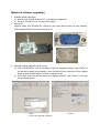
Method of software upgrading
1. Software install instrument
a) Double click “PXSDKToolkitV1.0.5” to install the upgrade flat
b) Execute “ISPWriter3.exe” to enter IAP program
2. Instrument
Upgrade board (667.42HW36-90), USB wire (one male terminal and one mini terminal),
VGA cable(665.D0002-510 with pin4 and pin11)
3. Upgrade method when the unit is normal
a) Click “ISPWRITER3” icon on the desk to open the upgrade software, click “OPEN” of
the tool bar to begin communication, enter the factory menu and select “Enter Update
Mode” of the first OSD page to enter the upgrade mode.
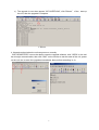
b) Click “BIN” of the tool bar and select the upgrade software, click “PROG” on the tool
bar to begin upgrade.
3. BIN 5. PROG
4.
Select the upgrade software

9
c) The upgrade is over when appear “ISP OVERFLOW”, click “Reboot” of the start-up
the unit, then the upgrade is complete.
4. Upgrade method when the unit can power on normally
Click “ISPWRITER3” icon on the desk to open the upgrade software, click “OPEN” on the tool
bar to begin communication, then click “DIAL” on the tool bar to test the state of the unit, power
on the unit now to enter the upgrade automatically, then perform according 3), 4).
6. Reboot

10
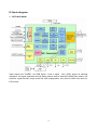
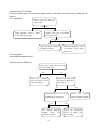
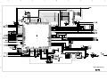
Working principle analysis of the unit
Antenna reception signal RF will be sent to integrative tuner (contain HF and IF amplifier circuit), the
tuner is controlled by the command (SDA and SCL) of the MCU N801(M16C), select appropriate
channel to system switch, via HF amplifier and IF amplifier decode, output video signal CVBS and
second sound signal SIF.
CVBS, AV1, AV2, S-Video signal (Y signal of S-Video and AV1 video share the same channel) and
D-SUB signal via matched resistance, the signal separately through alone channel send to main IC
NS01 (SVP-WX68) video switch, A/D transition, digital decode, image scale and OSD superposition,
then send to LVDS level drive for LCD screen.
Video signal of YPbPr1, YPbPr2 via matched resistance to video switch NB05 (PI5V330), after
switch the select signal will be sent to main IC NS01 (SVP-WX68) video switch, A/D transition,
digital decode, image scale and OSD superposition, then send to LVDS level drive for LCD screen.
HDMI1, HDMI2, HDMI3 digital signal via digital video switch NA04(PS301), select one signal to
send to main IC NS01 (SVP-WX68) video and audio separate first, video signal via digital decode,
image scale and OSD superposition to output LVDS level drive for LCD screen; digital audio signal
I2S will be sent to N103 (SGTV58xy audio process and volume control).
Audio signal of AV1, AV2(AV1 and S-Video share the same audio channel), YPbPr1, YPbPr2.
D-SUB/DVI HDMI and SIF signal will be sent to audio processor N103 (SGTV58xy) sound switch,
the select signal output through three ways. One way via volume, treble and bass control, sound
effect processing, then separate to left and right channel and send to sound amplifier NA01,
NA02(TPA3001D1) amplifying, then send to speaker; one way also separate to left and right
channel and send to earphone amplifier N104 (NJW1109) volume control and amplify, then send to
earphone socket; the other way send to AV OUT.

SDA/S I/O
I2C
I2 C
SIF1
HDMI I2S
HDMI I2S
AV Out
Mono TV-CVBS
D-SUB Audio
AV1 CVBS/ S_Video-Y LVDS
YPbPr2
S_Video- C
YPbPr1
AV2 CVBS
AV2
I2C
I2C
AV1/SV
RGB
YPbPr1
YPbPr
Program Update
YPbPr2
I2C
HDMI
IR / KEY / LED
Power
Standby Control
SVP-WX68
ADC
Decoder
Deinterlace
Scaler
Lvds driver
DDR
(4X32 Mbit)
PDP
PANEL
(63FH-
XD01)
SGTV58XY
AV1
JS-6S/121A2-A2
MCU(m16c)
TPA3001
AV
OUT
N
JW1109
(2X15W)
HDMI1
D-SUB
PI5V330
MCU
LPC915
RF
HP
AV
2
HDMI2
PS301
Flash
EDID
EDID
HDMI3
EDID
AV1
S-VIDEO
AV
2
JS-6S/121A2-A2
YPbPr1
YPbPr2
YPbPr1
YPbPr2
D
-
SUB
RTC
audio
video
tuner
Audio
Audio
Audio
Audio
Audio out
Audio processor
Switch
Audio amplifier
Earphone amplifier
Speaker
tuner
switch
switch
power manage
RS232 update
key
IR
power baord
board
board
Block diagram
11

12
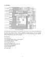
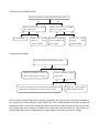
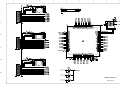
IC block diagram
1. DPTV-SVP-WX68
Video signal from TUNER1, AV, RGB signal, Y and C signal , YUV, YPbPr signal via matched
resistance, the signal separately through alone channel send to mainSVP-WX68 video switch, A/D
transition, digital decode, image scale and OSD superposition, then send to LVDS level drive for
LCD screen.

13
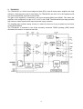
2. SGTV58xy
SGTV58xy has ten input channels for analog audio, SIF, audio of AV1,AV2 (AV1 and S-Video share
the same audio channel),YPbPr1, YPbPr2, D-SUB/DVI switched inside the IC by the software
control, the select audio via volume, treble/bass and sound effect processing to sound amplifier
through left/right channel, then send to speaker.
Pin Description
92, 93: SDA, SCL
37, 38: left/right channel output to sound amplifier
34, 35: left/right channel of earphone
32, 33: AV OUT (right/left)
43, 44: USB audio (right/left)
51, 52, 47, 48: YPbPr 1,2 audio (right/left)
53, 54, 49, 50: AV IN (right/left)
57, 58: VGA audio (right/left)
59, 60: TV MONO
81: TV SIF input

14
3. TPA3001D1
The TPA3001D1 is a 20-W mono bridge-tied load (BTL) class-D audio power amplifier with high
efficiency, eliminating the need for heat sinks. The TPA3001D1 can drive 4-Ω or 8-Ω speakers with
only a ferrite bead filter required to reduce EMI.
The gain of the amplifier is controlled by two input terminals,GAIN1 and GAIN0. This allows the
amplifier to be configured for a gain of 12, 18, 23.6, and 36 dB. The differential input stage provides
high common mode rejection and improved power supply rejection.
The amplifier also includes depop circuitry to reduce the amount of pop at power-up and when
cycling SHUTDOWN.
The TPA3001D1 is available in the 24-pin thermally enhanced TSSOP package (PWP) which
eliminates the need for an external heat sink.

15
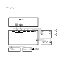
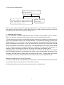
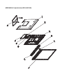
Wiring diagram
sound amplify board
vedio interface board
KEY board
IR board
main board
panel
power

16
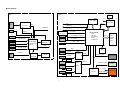
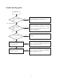
Trouble shooting guide
Power on
A red indicato
r
li
g
hts?
Check power board, IR board, power manage
IC N601(P89LPC915) and power cord
A blue indicato
r
li
g
hts?
Check if the pin2 of X401 is low level?
Check if CPU 42#, FLASH 26# is square
wave? Check the peripheral circuit of CPU
and FLSH/EEPROM.
N
o
N
o
Yes, turn the unit on
Panel is light
on?
N
o
Check if each power supply, LVDS signal is
normal?
Yes
Yes
Check if the picture of eac
h
channel is normal?
N
o
Check the signal inputted from the channel to
p
in IC or IC and its peripheral circuit or the
output of LVDS is normal
Check if the sound of each
channel is normal?
N
o
Check the signal inputted from the channel to
p
in IC is normal or IC(SGTV58xy/TPA3001)
and its periphery is normal.

17
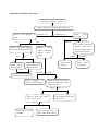
Check if each power suppl
y
of the main board is normal?
1.No raster, no picture, no sound
Check if the power supply indicator light is on.
Check 5V-S,
3.3V-SB
Cut off the connection
b
etween power boar
d
and main
b
oard, and tes
t
5V-S on power board
Check powe
r
manage IC
Power boar
d
has problem
Check if the indicator is
blue?
Power board has proble
m
Check CPU
(N801), FLASH
(N802) powe
r
supply.
Check if the pin2 o
f
X401is low level.
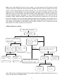
No raster, no picture, no sound.
Indicator is on
Yes
Indicator is off
N
o
Yes
N
o Abnormal
N
ormal
Power manage
IC has
p
roble
m
Abnormal
N
ormal
Check periphery o
f
L801
,
CPU and FLASH
Check if N801 10# turn to
high level 200ms later whe
n
CPU power on
Yes
N
o
Check if N801 42#, N802
26# is square wave
Check N801 reset circuit, i
f
CPU is reset
N
o
Yes
Yes
N
o
Check N801 crystal
and N806
Check the periphery o
f
N
801
,
N802
,
N803
,
N806
N
o
r
mal
Abnormal

18
Note: when check N801(CPU) pin10 is low voltage, you may disconnect R616 and test if V603
collector output low voltage first, then output high voltage all the while (the low voltage is CPU reset
signal, it turns to high voltage when working normally), if not, it’s power manage IC problem. Is there
square wave in FLASH pin26? If not, disconnect R851 and test if the square wave output from
N806 pin3, if still not, check N801 pin46-48 and N806. Check N801 pin42, if it has no square wave,
disconnect R856 and has a test again, if it has, perhaps N802(FLASH) is error. When check the
periphery of N801, N802 and N803, besides check the weld of the components, you may test the
pins of the resistance row connect N801, N802 and N803 with oscillograph, if the square wave is
abnormal, it indicates that one of them (N801, N802, N803) works abnormally and the SDL, SCL is
error, N802 in all probability. If RS51/RS52 connect N801 and NS01 is error, it will also cause the
phenomena of no raster, no picture and no sound.
2.With sound but no picture
Note: Please refer to checking procedure (4) to get the methods for checking the phenomenon of no
picture but with sound of HDMI channel.
With sound but no picture.
Display logo?
Check if all other channel
has no
p
icture.
Check the white
b
alance value o
f
the factory menu
Re-write the
software an
d
have a test
Check the signal
wave of XS01 wit
h
oscillograph.
Is the panel light or produce the
high voltage when power on
Check the input signal of N301
and N302 and
p
ower su
pp
l
y
.
Power board
dama
g
ed.
The panel
damaged.
Connect the
wire well
Yes
N
o
N
o
Yes
N
ormal
N
ormal Abnormal Abnormal
Abnormal
N
ormal
Follow the inpu
t
signal an
d
check the circuit
EEPROM
irritation an
d
adjust again
N
o Ye s
Is LVDS wire
normal?
Page is loading ...
Page is loading ...
Page is loading ...
Page is loading ...
Page is loading ...
Page is loading ...
Page is loading ...
Page is loading ...
Page is loading ...
Page is loading ...
Page is loading ...
Page is loading ...
Page is loading ...
Page is loading ...
Page is loading ...
Page is loading ...
Page is loading ...
Page is loading ...
Page is loading ...
Page is loading ...
Page is loading ...
Page is loading ...
Page is loading ...
Page is loading ...
Page is loading ...
Page is loading ...
Page is loading ...
-
 1
1
-
 2
2
-
 3
3
-
 4
4
-
 5
5
-
 6
6
-
 7
7
-
 8
8
-
 9
9
-
 10
10
-
 11
11
-
 12
12
-
 13
13
-
 14
14
-
 15
15
-
 16
16
-
 17
17
-
 18
18
-
 19
19
-
 20
20
-
 21
21
-
 22
22
-
 23
23
-
 24
24
-
 25
25
-
 26
26
-
 27
27
-
 28
28
-
 29
29
-
 30
30
-
 31
31
-
 32
32
-
 33
33
-
 34
34
-
 35
35
-
 36
36
-
 37
37
-
 38
38
-
 39
39
-
 40
40
-
 41
41
-
 42
42
-
 43
43
-
 44
44
-
 45
45
-
 46
46
-
 47
47


Ask a question and I''ll find the answer in the document
Finding information in a document is now easier with AI
Related papers
-
Sanyo LCD-22XR7SN User manual
-
Sanyo LCD-42XR9DA User manual
-
-
-
-
-
-
-
-
Other documents
-
Westinghouse Flat Panel Television LCD-TV User manual
-
Akai Computer Monitor PDP4273M User manual
-
 Ovideon Flat Panel Television LC2700w User manual
-
Prima PH-42FB7 User manual
-
V7 LTV30C-1BNDL Datasheet
-
-
-
Avantree BTSP-NB05 Wireless Personal Speaker User manual
-
 Convex CX-I7030 User manual
-

