Supermicro SSE-X3348S Installation guide
- Category
- Network switches
- Type
- Installation guide
This manual is also suitable for

SSE-X3348S
SSE-X3348SR
48-Port 10G
Top-of-Rack Switch
Installation Manual
Revison 1.0

ii
The information in this Installation Manual has been carefully reviewed and is believed to be accurate.
The vendor assumes no responsibility for any inaccuracies that may be contained in this document,
makes no commitment to update or to keep current the information in this manual, or to notify any person
or organization of the updates. Please Note: For the most up-to-date version of this manual, please
see our web site at www.supermicro.com.
Super Micro Computer, Inc. (“Supermicro”) reserves the right to make changes to the product described
in this manual at any time and without notice. This product, including software, if any, and documentation
may not, in whole or in part, be copied, photocopied, reproduced, translated or reduced to any medium or
machine without prior written consent.
IN NO EVENT WILL SUPERMICRO BE LIABLE FOR DIRECT, INDIRECT, SPECIAL, INCIDENTAL,
SPECULATIVE OR CONSEQUENTIAL DAMAGES ARISING FROM THE USE OR INABILITY TO USE
THIS PRODUCT OR DOCUMENTATION, EVEN IF ADVISED OF THE POSSIBILITY OF SUCH
DAMAGES. IN PARTICULAR, SUPERMICRO SHALL NOT HAVE LIABILITY FOR ANY HARDWARE,
SOFTWARE, OR DATA STORED OR USED WITH THE PRODUCT, INCLUDING THE COSTS OF
REPAIRING, REPLACING, INTEGRATING, INSTALLING OR RECOVERING SUCH HARDWARE,
SOFTWARE, OR DATA.
Any disputes arising between manufacturer and customer shall be governed by the laws of Santa Clara
County in the State of California, USA. The State of California, County of Santa Clara shall be the
exclusive venue for the resolution of any such disputes. Super Micro's total liability for all claims will not
exceed the price paid for the hardware product.
FCC Statement: This equipment has been tested and found to comply with the limits for a Class A digital
device pursuant to Part 15 of the FCC Rules. These limits are designed to provide reasonable protection
against harmful interference when the equipment is operated in a commercial environment. This
equipment generates, uses, and can radiate radio frequency energy and, if not installed and used in
accordance with the manufacturer’s instruction manual, may cause harmful interference with radio
communications. Operation of this equipment in a residential area is likely to cause harmful interference,
in which case you will be required to correct the interference at your own expense.
California Best Management Practices Regulations for Perchlorate Materials: This Perchlorate warning
applies only to products containing CR (Manganese Dioxide) Lithium coin cells. Perchlorate
Material-special handling may apply. See www.dtsc.ca.gov/hazardouswaste/perchlorate for further
details.
Manual Revison 1.0
Release Date: March 20, 2013
Unless you request and receive written permission from Super Micro Computer, Inc., you may not copy
any part of this document.
Information in this document is subject to change without notice. Other products and companies referred
to herein are trademarks or registered trademarks of their respective companies or mark holders.
Copyright © 2013 by Super Micro Computer, Inc.
All rights reserved.
Printed in the United States of America
WARNING: HANDLING OF LEAD SOLDER MATERIALS USED IN THIS
PRODUCT MAY EXPOSE YOU TO LEAD, A CHEMICAL KNOWN TO THE
STATE OF CALIFORNIA TO CAUSE BIRTH DEFECTS AND OTHER
REPRODUCTIVE HARM.

iii
:
Preface
About this Manual
This manual is written for professional system integrators, Information Technology
professionals, service personnel, technicians and network administrators who are
responsible for installing and setting up network equipment; consequently, it assumes a
basic working knowledge of LANs (Local Area Networks). It provides information for the
installation and use of the Supermicro's SSE-X3348S/SSE-X3348SR switches.
Installation and maintenance should be performed by experienced professionals only.
Manual Organization
Chapter 1: Introduction
The first chapter provides a checklist of the main components included with the switch
and describes its main features.
Chapter 2: System Safety
You should familiarize yourself with this chapter for a general overview of safety
precautions that should be followed when installing and servicing the switch.
Chapter 3: Network Planning
Refer here for details on network planning for the switch.
Chapter 4: Installation
This chapter describes how to install the switch.
Chapter 5: Connecting
This chapter covers how to connect the switches to PCs and servers, as well as to other
switches and hubs.
Chapter 6: Hardware Specifications
This chapter lists and describes hardware specifications for the switch.
Chapter 7: Switch Management
This chapter lists and describes switch management software for the switch.
Chapter 8: Troubleshooting
This chapter covers troubleshooting issues for the switch.

SSE-X3348S/SSE-X3348SR Switch Installation Manual
iv
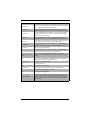
Glossary
Glossary Term Description
10BASE-T
IEEE 802.3 specification for 10 Mbps Ethernet over two pairs of Category
3, 4, or 5 UTP cable.
100BASE-FX
IEEE 802.3 specification for 100 Mbps Ethernet over two strands of 50/
125, 62.5/125 micron, or 9/125 micron core fiber cable.
100BASE-TX
IEEE 802.3u specification for 100 Mbps Ethernet over two pairs of
Category 5 UTP cable.
1000BASE-LX
IEEE 802.3z specification for Gigabit Ethernet over two strands of 50/125,
62.5/125 or 9/125 micron core fiber cable.
1000BASE-LH
Specification for long-haul Gigabit Ethernet over two strands of 9/125
micron core fiber cable.
1000BASE-SX
IEEE 802.3z specification for Gigabit Ethernet over two strands of 50/125
or 62.5/125 micron core fiber cable.
1000BASE-T
IEEE 802.3ab specification for Gigabit Ethernet over 100-ohm Category 5,
5e or 6 twisted-pair cable (using all four wire pairs).
10GBASE-T
IEEE 802.3an-2006 specification for 10-Gigabit Ethernet over 100-ohm
category 6 or 6A twisted pair cable (using all four wire pairs) over distances
of up to 100 meters (330-ft.).
Auto-Negotiation
Signalling method allowing each node to select its optimum operational
mode (e.g., speed and duplex mode) based on the capabilities of the node
to which it is connected.
Bandwidth
The difference between the highest and lowest frequencies available for
network signals. Also synonymous with wire speed, the actual speed of the
data transmission along the cable.
Collision Domain Single CSMA/CD LAN segment.
CSMA/CD
CSMA/CD (Carrier Sense Multiple Access/Collision Detect) is the
communication method employed by Ethernet, Fast Ethernet, and Gigabit
Ethernet.
End Station A workstation, server, or other device that does not forward traffic.
Ethernet
A network communication system developed and standardized by DEC,
Intel, and Xerox, using baseband transmission, CSMA/CD access, logical
bus topology, and coaxial cable. The successor IEEE 802.3 standard
provides for integration into the OSI model and extends the physical layer
and media with repeaters and implementations that operate on fiber, thin
coax and twisted-pair cable.
Fast Ethernet
A 100 Mbps network communication system based on Ethernet and the
CSMA/CD access method.
Full Duplex
Transmission method that allows two network devices to transmit and
receive concurrently, effectively doubling the bandwidth of that link.
Gigabit Ethernet
A 1000 Mbps network communication system based on Ethernet and the
CSMA/CD access method.
IEEE Institute of Electrical and Electronic Engineers.

v
:
IEEE 802.3
Defines carrier sense multiple access with collision detection (CSMA/CD)
access method and physical layer specifications.
IEEE 802.3ab
Defines CSMA/CD access method and physical layer specifications for
1000BASE-T Gigabit Ethernet. (Now incorporated in IEEE 802.3-2005.)
IEEE 802.3az
Defines the IEEE 8023az specification for enhancing the twisted-pair and
backplane Ethernet standards that allows for less power consumption
during periods of low data activity.
IEEE 802.3u
Defines CSMA/CD access method and physical layer specifications for
100BASE-TX Fast Ethernet. (Now incorporated in IEEE 802.3-2005.)
IEEE 802.3x
Defines Ethernet frame start/stop requests and timers used for flow control
on full-duplex links. (Now incorporated in IEEE 802.3-2005.)
IEEE 802.3z
Defines CSMA/CD access method and physical layer specifications for
1000BASE Gigabit Ethernet. (Now incorporated in IEEE 802.3-2005.)
LAN Segment Separate LAN or collision domain.
LED Light emitting diode used for monitoring a device or network condition.
Local Area Network (LAN) A group of interconnected computer and support devices.
Media Access Control
(MAC)
A portion of the networking protocol that governs access to the
transmission medium, facilitating the exchange of data between network
nodes.
MIB
An acronym for Management Information Base. It is a set of database
objects that contains information about the device.
RJ-45 Connector A connector for twisted-pair wiring.
STP Shielded Twisted Pair.
SMPS Switching Mode Power Supply.
Switched Ports Ports that are on separate collision domains or LAN segments.
TIA Telecommunications Industry Association
UTP Un-shielded twisted-pair cable.
Virtual LAN (VLAN)
A Virtual LAN is a collection of network nodes that share the same collision
domain regardless of their physical location or connection point in the
network. A VLAN serves as a logical workgroup with no physical barriers,
allowing users to share information and resources as though located on
the same LAN.
Glossary Term Description

SSE-X3348S/SSE-X3348SR Switch Installation Manual
vi
Notes

vii
Table of Contents
Chapter 1 Introduction.......................................................................1-1
1-1 Overview.............................................................................................1-1
1-2 Key Hardware Components............................................................1-2
10G SFP+ Slots......................................................................................1-2
40G QSFP+ Slots ...................................................................................1-2
1000BASE-T RJ-45 Ports.......................................................................1-2
Reset Button...........................................................................................1-3
System LEDs..........................................................................................1-3
Port LEDs................................................................................................1-3
Console Port...........................................................................................1-3
USB Port.................................................................................................1-3
Fan Tray Module.....................................................................................1-3
Power Supply Modules...........................................................................1-3
Chapter 2 Standardized Warning Statements.....................2-1
2-1 About Standardized Warning Statements......................................2-1
Warning Definition...................................................................................2-1
Installation Instructions ...........................................................................2-3
Circuit Breaker........................................................................................2-4
Power Disconnection Warning................................................................2-5
Equipment Installation.............................................................................2-6
Restricted Area.......................................................................................2-7
Battery Handling .....................................................................................2-9
Redundant Power Supplies ..................................................................2-10
Backplane Voltage................................................................................2-11
Comply with Local and National Electrical Codes.................................2-12
Product Disposal...................................................................................2-13
Hot Swap Fan Warning.........................................................................2-14
Power Cable and AC Adapter ..............................................................2-15
Chapter 3 Network Planning..........................................................3-1
3-1 Data Center Deployment .................................................................3-1
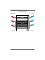
3-2 Rack Cooling......................................................................................3-3

SSE-X3348S/SSE-X3348SR Switch Installation Manual
viii
Chapter 4 Installing the Switch....................................................4-1
4-1 Package Contents.............................................................................4-1
4-2 Switch Chassis ..................................................................................4-1
General Installation Guidelines...............................................................4-1
How to Install the Switch in a Rack.........................................................4-2
Rack-Mounting Items...........................................................................4-2
Rack-Mount Procedure........................................................................4-2
Switch Cooling Requirements.................................................................4-2
Rack Cooling........................................................................................4-4
Fan Tray Module..................................................................................4-4
4-3 Switch Installation Tasks..................................................................4-4
Task 1: Unpack package and check contents.........................................4-4
Task 2: Install the Chassis ......................................................................4-4
Task 3: Install Power Modules and Power On ........................................4-5
Task 4: Verify Switch Operation..............................................................4-7
Task 5: Make Initial Configuration Changes............................................4-8
Task 6: Install Transceivers and Connect Cables...................................4-9
4-4 Power and Grounding.....................................................................4-10
Power Supply Modules.........................................................................4-10
Grounding the Chassis .........................................................................4-12
How to Connect to AC Power...............................................................4-12
Chapter 5 Making Network Connections...............................5-1
5-1 Cable Labeling and Connection Records......................................5-1
5-2 Understanding the Port Status LEDs.............................................5-2
5-3 How to Install an SFP/SFP+/QSFP+ Transceiver........................5-3
5-4 How to Connect to Twisted-Pair Copper Ports.............................5-5
Copper Cabling Guidelines.....................................................................5-5
10/100BASE-TX Pin Assignments..........................................................5-6
1000BASE-T Pin Assignments...............................................................5-7
1000BASE-T Cable Requirements ......................................................5-7
Connection Procedure............................................................................5-8
5-5 How to Connect to SFP/SFP+ Fiber Optic Ports .........................5-9
Connection Procedure............................................................................5-9
5-6 How to Connect to QSFP+ Fiber Optic Ports.............................5-11
Connection Procedure..........................................................................5-11
5-7 DAC Connections............................................................................5-12
Making DAC Connections.....................................................................5-14

ix
Table of Contents
Chapter 6 Hardware Specifications...........................................6-1
6-1 Physical Characteristics...................................................................6-1
6-2 Switch Features.................................................................................6-2
6-3 Management Features.....................................................................6-2
6-4 Standards ...........................................................................................6-3
6-5 Compliances ......................................................................................6-3
Chapter 7 Switch Management ....................................................7-1
7-1 Understanding the System Status LEDs.......................................7-1
7-2 How to Connect to the Console Port .............................................7-2
7-3 How to Reset the Switch..................................................................7-4
Chapter 8 Troubleshooting.............................................................8-1
8-1 Diagnosing LED Indicators..............................................................8-1
8-2 System Self-Diagnostic Test Failure..............................................8-1
8-3 Power and Cooling Problems..........................................................8-1
8-4 Installation ..........................................................................................8-2
8-5 In-Band Access .................................................................................8-2

SSE-X3348S/SSE-X3348SR Switch Installation Manual
x
Notes

1-1
Chapter 1
Introduction
1-1 Overview
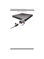
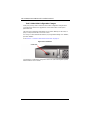
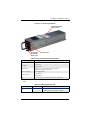
The SSE-X3348S/SSE-X3348SR switch is a high-performance top-of-rack switch,
designed for data center operating environments. The switch provides 48 10G Small
Form Factor Pluggable Plus (SFP+) ports, four 40G Quad SFP+ (QSFP+) ports, and
two 1G RJ-45 ports (see Figure 1-1 below). The switch also includes replaceable dual
power supply units and a fan tray module.
The switch supports a full set of Layer 2 switching, data center bridging, and Layer 3
routing features. The switch can be deployed as a top-of-rack (TOR) or distributed spine
switch to form a network fabric that can reduce infrastructure expenses and power
consumption in the data center. This network fabric can be used to interconnect tens of
thousands of servers delivering cloud computing services.
The SSE-X3348S switch provides front-to-back (F2B) airflow cooling. The companion
product, SSE-X3348SR, provides a “reverse” airflow – back-to-front (B2F). The airflow
options enable flexibility on rack deployment with servers or other switches, allowing
cool aisles to be maintained without creating “hot loops.”

SSE-X3348S/SSE-X3348SR Switch Installation Manual
1-2
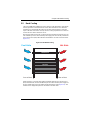
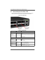
1-2 Key Hardware Components
The switch consists of several key hardware components (Figure 1-1). This manual
describes each specific component, or related components, together with their
installation requirements and procedures in each chapter. To understand each
component in detail, refer to the relevant section.
Figure 1-1. Front and Rear Panels
10G SFP+ Slots
The switch contains 48 Small Form Factor Pluggable Plus (SFP+) transceiver slots that
support 10G Ethernet SFP+ transceivers, or Gigabit Ethernet SFP transceivers. For
more information, see Section 5-5: "How to Connect to SFP/SFP+ Fiber Optic Ports" on
page 5-9.
40G QSFP+ Slots
The switch contains four Quad Small Form Factor Pluggable Plus (QSFP+) transceiver
slots that operate up to 40 Gbps full duplex. For more information, see Section 5-6:
"How to Connect to QSFP+ Fiber Optic Ports" on page 5-11.
1000BASE-T RJ-45 Ports
The switch includes two 1000BASE-T RJ-45 ports. For more information, see
Section 5-4: "How to Connect to Twisted-Pair Copper Ports" on page 5-5.
Port LEDs
System Indicators
1000BASE-T Ports
Reset Button
Console Port
Fan Tray Module
Front Panel
Rear Panel
10G SFP+ Ports 40G QSFP+ Ports
USB Port
Power Supply Modules

1-3
Chapter 1: Introduction
Reset Button
Pressing the reset button on the front panel causes the switch to preform a hard reset.
For more information, see “Section 7-3: "How to Reset the Switch" on page 7-4.
System LEDs
For information on system status LED indicators, see Section 7-1: "Understanding the
System Status LEDs" on page 7-1.
Port LEDs
For information on port status LED indicators, see Section 5-2: "Understanding the Port
Status LEDs" on page 5-2.
Console Port
The DB-9 connector on the rear panel labeled “Console” provides an out-of-band serial
connection to a terminal or a PC running terminal emulation software. The port can be
used for performing switch monitoring and configuration. For more information, see
Section 7-2: "How to Connect to the Console Port" on page 7-2.
USB Port
The USB port on the switch rear panel is reserved for future use.
Fan Tray Module
The fan tray module provides air cooling for the switch system. For more information,
see Section : "Switch Cooling Requirements" on page 4-2.
Power Supply Modules
The switch supports dual hot-swappable AC power supply units (PSUs). You can install
up to two PSUs with matching airflow direction in the switch. For more information on
the switch power supplies, how to intall them, and how to power-on the switch, see
Section 4-3: "Switch Installation Tasks" on page 4-4.

SSE-X3348S/SSE-X3348SR Switch Installation Manual
1-4
Notes

2-1
Chapter 2
Standardized Warning Statements
2-1 About Standardized Warning Statements
The following statements are industry standard warnings, provided to warn the user of
situations which have the potential for bodily injury. Should you have questions or
experience difficulty, contact Supermicro's Technical Support department for assistance.
Only certified technicians should attempt to install or configure components.
Read this appendix in its entirety before installing or configuring components in the
Supermicro chassis.
These warnings may also be found on our web site at http://
www.supermicro.com/about/policies/safety_information.cfm.
Warning Definition
Warning!
This warning symbol means danger. You are in a situation that could cause
bodily injury. Before you work on any equipment, be aware of the hazards
involved with electrical circuitry and be familiar with standard practices for preventing
accidents.
此警告符号代表危险。
您正处于可能受到严重伤害的工作环境中。在您使用设备开始工作之前,必须充分意识到
触电的危险,并熟练掌握防止事故发生的标准工作程序。请根据每项警告结尾的声明号码
找到此设备的安全性警告说明的翻译文本。
此警告符號代表危險。
您正處於可能身體可能會受損傷的工作環境中。在您使用任何設備之前,請注意觸電的危
險,並且要熟悉預防事故發生的標準工作程序。請依照每一注意事項後的號碼找到相關的
翻譯說明內容。

SSE-X3348S/SSE-X3348SR Switch Installation Manual
2-2
Warnung
WICHTIGE SICHERHEITSHINWEISE
Dieses Warnsymbol bedeutet Gefahr. Sie befinden sich in einer Situation, die zu
Verletzungen führen kann. Machen Sie sich vor der Arbeit mit Geräten mit den Gefahren
elektrischer Schaltungen und den üblichen Verfahren zur Vorbeugung vor Unfällen
vertraut. Suchen Sie mit der am Ende jeder Warnung angegebenen
Anweisungsnummer nach der jeweiligen Übersetzung in den übersetzten
Sicherheitshinweisen, die zusammen mit diesem Gerät ausgeliefert wurden.
BEWAHREN SIE DIESE HINWEISE GUT AUF.
INSTRUCCIONES IMPORTANTES DE SEGURIDAD
Este símbolo de aviso indica peligro. Existe riesgo para su integridad física. Antes de
manipular cualquier equipo, considere los riesgos de la corriente eléctrica y
familiarícese con los procedimientos estándar de prevención de accidentes. Al final de
cada advertencia encontrará el número que le ayudará a encontrar el texto traducido en
el apartado de traducciones que acompaña a este dispositivo.
GUARDE ESTAS INSTRUCCIONES.
IMPORTANTES INFORMATIONS DE SÉCURITÉ
Ce symbole d'avertissement indique un danger. Vous vous trouvez dans une situation
pouvant entraîner des blessures ou des dommages corporels. Avant de travailler sur un
équipement, soyez conscient des dangers liés aux circuits électriques et
familiarisez-vous avec les procédures couramment utilisées pour éviter les accidents.
Pour prendre connaissance des traductions des avertissements figurant dans les
consignes de sécurité traduites qui accompagnent cet appareil, référez-vous au numéro
de l'instruction situé à la fin de chaque avertissement.
CONSERVEZ CES INFORMATIONS.
ןןונקת תורהצהאהרהז
ןה תואבה תורהצהא ינפמ שמתשמה תא ריהזהל תנמ לע ,היישעתה ינקת יפ לע תורהז הלבח
ה וא תולאש שיו הדימב .תירשפא תיזיפי ,יהשלכ היעבב תולקתרוציל שי הכימת תקלחמ םע רשק
רידגהל וא ןיקתהל םיאשר דבלב םיכמסומ םיאנכט .ורקימרפוס לש תינכט תאה .םיביכר
אורקל שי .ורקימרפוס יזראמב םיביכרה תרדגה וא תנקתה ינפל ואולמב חפסנה תא
. ﻲﻓ ﻚﻧﺍ ﻥﺃ ﻦﻜﻤﻳ ﺔﻟﺎﺣ ﻲﻓ ﺐﺒﺴﺘﺗ ﺔﺑﺎﺻﺍ ﺔﻳﺪﺴﺟ ﺰﻣﺮﻟﺍ ﺍﺬﻫ ﻲﻨﻌﻳ ﺮﻄﺧ !ﺮﻳﺬﺤﺗ
ﻥﺃ ﻞﺒﻗ ﻱﺃ ﻰﻠﻋ ﻞﻤﻌﺗ ﺕﺍﺪﻌﻣ،ﻛﻢﻠﻋ ﻰﻠﻋ ﻦ ﻦﻋ ﺔﻤﺟﺎﻨﻟﺍ ﺮﻁﺎﺨﻤﻟﺎﺑ ﺮﺋﺍﻭﺪﻟﺍ
ﺔﻴﺋﺎﺑﺮﻬﻜﻟﺍ
ﻛﻭﺔﻳﺍﺭﺩ ﻰﻠﻋ ﻦ ﺭﺎﻤﻤﻟﺎﺑﺕﺎﺳ ﺔﻴﺋﺎﻗﻮﻟﺍ ﻟ ﻊﻨﻤﻉﻮﻗﻭ ﻱﺃﺙﺩﺍﻮﺣ
ﻢﻗﺭ ﻡﺪﺨﺘﺳﺍ ﻥﺎﻴﺒﻟﺍ ﺹﻮﺼﻨﻤﻟﺍ ﺔﻳﺎﻬﻧ ﻲﻓ ﺮﻳﺬﺤﺗ ﻞﻛ ﺭﻮﺜﻌﻠﻟ ﺎﻬﺘﻤﺟﺮﺗ

2-3
Chapter 2: Standardized Warning Statements
BELANGRIJKE VEILIGHEIDSINSTRUCTIES
Dit waarschuwings symbool betekent gevaar. U verkeert in een situatie die lichamelijk
letsel kan veroorzaken. Voordat u aan enige apparatuur gaat werken, dient u zich
bewust te zijn van de bij een elektrische installatie betrokken risico's en dient u op de
hoogte te zijn van de standaard procedures om ongelukken te voorkomen. Gebruik de
nummers aan het eind van elke waarschuwing om deze te herleiden naar de
desbetreffende locatie.
BEWAAR DEZE INSTRUCTIES
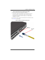
Installation Instructions
Warning!
Read the installation instructions before connecting the system to the power
source.
警告
将此系统连接电源前 , 请先阅读安装说明。
警告
將系統與電源連接前,請先閱讀安裝說明。
Warnung
Vor dem Anschließen des Systems an die Stromquelle die Installationsanweisungen
lesen.
¡Advertencia!
Lea las instrucciones de instalación antes de conectar el sistema a la red de
alimentación.
Attention
Avant de brancher le système sur la source d'alimentation, consulter les directives
d'installation.
אורקל שי רוקמל תכרעמה רוביח ינפל הנקתה תוארוה תאחתמ.

SSE-X3348S/SSE-X3348SR Switch Installation Manual
2-4
Waarschuwing
Raadpleeg de installatie-instructies voordat u het systeem op de voedingsbron aansluit.
Circuit Breaker
Warning!
This product relies on the building's installation for short-circuit (overcurrent)
protection. Ensure that the protective device is rated not greater than: 250 V,
20 A.
警告
此产品的短路 ( 过载电流 ) 保护由建筑物的供电系统提供 , 确保短路保护设备的额定电流
不大于 250V,20A。
警告
此產品的短路 ( 過載電流 ) 保護由建築物的供電系統提供 , 確保短路保護設備的額定電
流不大於 250V,20A。
Warnung
Dieses Produkt ist darauf angewiesen, dass im Gebäude ein Kurzschluss- bzw.
Überstromschutz installiert ist. Stellen Sie sicher, dass der Nennwert der
Schutzvorrichtung nicht mehr als: 250 V, 20 A beträgt.
¡Advertencia!
Este equipo utiliza el sistema de protección contra cortocircuitos (o sobrecorrientes) del
edificio. Asegúrese de que el dispositivo de protección no sea superior a: 250 V, 20 A.
Attention
Pour ce qui est de la protection contre les courts-circuits (surtension), ce produit dépend
de l'installation électrique du local. Vérifiez que le courant nominal du dispositif de
protection n'est pas supérieur à :250 V, 20 A.
ﻟﺍ ﺕﺍﺩﺎﺷﺭﺇ ﺮﻗﺍﺐﻴﻛﺮﺘ ﻞﻴﺻﻮﺗ ﻞﺒﻗ ﻰﻟﺇ ﻡﺎﻈﻨﻟﺍ ﺔﻗﺎﻄﻠﻟ ﺭﺪﺼﻣ
לע ךמתסמ הז רצומנגהה תעינמל םינבמב תנקתומה יכ אדוול שי .ילמשח רצק
רצקה ינפמ ןגמה רישכמה ילמשחהמ רתוי אל אוה-250 V, 20 A

2-5
Chapter 2: Standardized Warning Statements
Waarschuwing
Dit product is afhankelijk van de kortsluitbeveiliging (overspanning) van uw electrische
installatie. Controleer of het beveiligde aparaat niet groter gedimensioneerd is dan
220V, 20A.
Power Disconnection Warning
Warning!
The system must be disconnected from all sources of power and the power
cord removed from the power supply module(s) before accessing the chassis
interior to install or remove system components.
警告
在你打开机箱并安装或移除内部器件前 , 必须将系统完全断电 , 并移除电源线。
警告
在您打開機殼安裝或移除內部元件前,必須將系統完全斷電,並移除電源線。
Warnung
Das System muss von allen Quellen der Energie und vom Netzanschlusskabel getrennt
sein, das von den Spg.Versorgungsteilmodulen entfernt wird, bevor es auf den
Chassisinnenraum zurückgreift, um Systemsbestandteile anzubringen oder zu
entfernen.
ﺞﺘﻨﻤﻟﺍ ﺍﺬﻫ ﻰﻠﻋ ﺪﻤﺘﻌﻳ ﺕﺍﺪﻌﻣ ﺔﻳﺎﻤﺤﻟﺍ ﺓﺮﻴﺼﻘﻟﺍﺮﺋﺍﻭﺪﻟﺍ ﻦﻣ ﺎﻬﺘﻴﺒﺜﺗ ﻢﺗ ﻲﺘﻟﺍ ﻲﻓ
ﻰﻨﺒﻤﻟﺍ
20A, 250V : ﻦﻣ ﺪﻛﺄﺗ ﻥﺃ ﻢﻴﻴﻘﺗ ﺯﺎﻬﺠﻟﺍ ﻟﺍﻲﺋﺎﻗﻮ ﺲﻴﻟ ﻦﻣ ﺮﺜﻛﺃ

SSE-X3348S/SSE-X3348SR Switch Installation Manual
2-6
¡Advertencia!
El sistema debe ser disconnected de todas las fuentes de energía y del cable eléctrico
quitado de los módulos de fuente de alimentación antes de tener acceso el interior del
chasis para instalar o para quitar componentes de sistema.
Attention
Le système doit être débranché de toutes les sources de puissance ainsi que de son
cordon d'alimentation secteur avant d'accéder à l'intérieur du chassis pour installer ou
enlever des composants de systéme.
Waarschuwing
Voordat u toegang neemt tot het binnenwerk van de behuizing voor het installeren of
verwijderen van systeem onderdelen, dient u alle spanningsbronnen en alle
stroomkabels aangesloten op de voeding(en) van de behuizing te verwijderen.
Equipment Installation
Warning!
Only trained and qualified personnel should be allowed to install, replace, or
service this equipment.
警告
只有经过培训且具有资格的人员才能进行此设备的安装、更换和维修。
警告
只有經過受訓且具資格人員才可安裝、更換與維修此設備。
יילמשח קותינ ינפמ הרהזא
!הרהזא
למשחה תורוקמ לכמ תכרעמה תא קתנל שי ריסהל שיו קפסהמ ילמשחה לבכ תא
נקתה ךרוצל זראמה לש ימינפה קלחל השיג ינפלת רסה ואת .םיביכר
ﻞﺼﻓ ﺐﺠﻳ ﻡﺎﻈﻨﻟﺍ ﻊﻴﻤﺟ ﻦﻣﺭﺩﺎﺼﻣ ﺔﻗﺎﻄﻟﺍ ﺔﻟﺍﺯﺇﻭ ءﺎﺑﺮﻬﻜﻟﺍ ﻚﻠﺳ ﻦﻣ ﺓﺪﺣﻭ ﺩﺍﺪﻣﺍ
ﺔﻗﺎﻄﻟﺍ ﻞﺒﻗ
ﻰﻟﺇ ﻝﻮﺻﻮﻟﺍ ﺔﻴﻠﺧﺍﺪﻟﺍ ﻖﻁﺎﻨﻤﻟﺍ ﻟﻞﻜﻴﻬﻠ ﺔﻟﺍﺯﺇ ﻭﺃ ﺖﻴﺒﺜﺘﻟ ﺕﺎﻧﻮﻜﻣ ﺯﺎﻬﺠﻟﺍ
Page is loading ...
Page is loading ...
Page is loading ...
Page is loading ...
Page is loading ...
Page is loading ...
Page is loading ...
Page is loading ...
Page is loading ...
Page is loading ...
Page is loading ...
Page is loading ...
Page is loading ...
Page is loading ...
Page is loading ...
Page is loading ...
Page is loading ...
Page is loading ...
Page is loading ...
Page is loading ...
Page is loading ...
Page is loading ...
Page is loading ...
Page is loading ...
Page is loading ...
Page is loading ...
Page is loading ...
Page is loading ...
Page is loading ...
Page is loading ...
Page is loading ...
Page is loading ...
Page is loading ...
Page is loading ...
Page is loading ...
Page is loading ...
Page is loading ...
Page is loading ...
Page is loading ...
Page is loading ...
Page is loading ...
Page is loading ...
Page is loading ...
Page is loading ...
Page is loading ...
Page is loading ...
Page is loading ...
Page is loading ...
Page is loading ...
Page is loading ...
Page is loading ...
Page is loading ...
Page is loading ...
Page is loading ...
Page is loading ...
Page is loading ...
-
 1
1
-
 2
2
-
 3
3
-
 4
4
-
 5
5
-
 6
6
-
 7
7
-
 8
8
-
 9
9
-
 10
10
-
 11
11
-
 12
12
-
 13
13
-
 14
14
-
 15
15
-
 16
16
-
 17
17
-
 18
18
-
 19
19
-
 20
20
-
 21
21
-
 22
22
-
 23
23
-
 24
24
-
 25
25
-
 26
26
-
 27
27
-
 28
28
-
 29
29
-
 30
30
-
 31
31
-
 32
32
-
 33
33
-
 34
34
-
 35
35
-
 36
36
-
 37
37
-
 38
38
-
 39
39
-
 40
40
-
 41
41
-
 42
42
-
 43
43
-
 44
44
-
 45
45
-
 46
46
-
 47
47
-
 48
48
-
 49
49
-
 50
50
-
 51
51
-
 52
52
-
 53
53
-
 54
54
-
 55
55
-
 56
56
-
 57
57
-
 58
58
-
 59
59
-
 60
60
-
 61
61
-
 62
62
-
 63
63
-
 64
64
-
 65
65
-
 66
66
-
 67
67
-
 68
68
-
 69
69
-
 70
70
-
 71
71
-
 72
72
-
 73
73
-
 74
74
-
 75
75
-
 76
76


Supermicro SSE-X3348S Installation guide
- Category
- Network switches
- Type
- Installation guide
- This manual is also suitable for
Ask a question and I''ll find the answer in the document
Finding information in a document is now easier with AI
Related papers
-
Supermicro SSE-G3648B Installation guide
-
-
-
Supermicro SSE-X24S/R User manual
-
-
-
Supermicro SSE-G48-TG4 User manual
-
-
-
Other documents
-
Digisol DG-CS4554FFv2 Quick Installation Guide
-
VIA Technologies VNT5103Q28PS Installation guide
-
Add-On Computer Peripherals (ACP) ADD-MCC40GQSFP User manual
-
 QUANTA QuantaMesh T3048-LY2R Installation guide
-
Alcatel-Lucent OS-LS-6248 User manual
-
SUPER MICRO Computer SSE-G48-TG4 User manual
-
ADTRAN NetVanta 1748F Series Quick Start
-
CTS FOS-5152 User manual
-
3com 3C17718 Quick Installation Manual
-
 QUANTA T3048-LY2 Installation guide

