Page is loading ...

COPYRIGHT © SEPTEMBER, 2007 BY GRIZZLY INDUSTRIAL, INC.
WARNING: NO PORTION OF THIS MANUAL MAY BE REPRODUCED IN ANY SHAPE
OR FORM WITHOUT THE WRITTEN APPROVAL OF GRIZZLY INDUSTRIAL, INC.
#JM9927 PRINTED IN CHINA
MODEL H8225
2
1
⁄2 GALLON PAINT TANK
WITH GUN
INSTRUCTION MANUAL

This manual provides critical safety instructions on the proper setup,
operation, maintenance, and service of this machine/tool. Save this
document, refer to it often, and use it to instruct other operators.
Failure to read, understand and follow the instructions in this manual
may result in fire or serious personal injury—including amputation,
electrocution, or death.
The owner of this machine/tool is solely responsible for its safe use.
This responsibility includes but is not limited to proper installation in
a safe environment, personnel training and usage authorization,
proper inspection and maintenance, manual availability and compre-
hension, application of safety devices, cutting/sanding/grinding tool
integrity, and the usage of personal protective equipment.
The manufacturer will not be held liable for injury or property damage
from negligence, improper training, machine modifications or misuse.
Some dust created by power sanding, sawing, grinding, drilling, and
other construction activities contains chemicals known to the State
of California to cause cancer, birth defects or other reproductive
harm. Some examples of these chemicals are:
• Lead from lead-based paints.
• Crystalline silica from bricks, cement and other masonry products.
• Arsenic and chromium from chemically-treated lumber.
Your risk from these exposures varies, depending on how often you
do this type of work. To reduce your exposure to these chemicals:
Work in a well ventilated area, and work with approved safety equip-
ment, such as those dust masks that are specially designed to filter
out microscopic particles.

-1-Model H8225 2
1
⁄2 Gallon Paint Tank with Gun
Safety Instructions for Pneumatic Tools
1. READ THIS MANUAL. This tool may
cause personal injury if used incor-
rectly. This manual contains proper
safety and operating instructions that
must be followed to reduce this risk.
2. WEAR EYE PROTECTION. This
tool may throw small fragments dur-
ing operation, which may cause seri-
ous eye injury. Always wear ANSI
approved safety glasses or face shield
to reduce your risk from this hazard.
3. WEAR A RESPIRATOR. This tool
may produce fine dust during oper-
ation, which can cause respiratory
injury if inhaled. Always wear a respi-
rator NIOSH approved for the type of
material being processed.
For Your Own Safety Read Instruction Manual
Before Operating This Equipment
The purpose of safety symbols is to attract your attention to possible hazardous
conditions. This manual uses a series of symbols and signal words which
are intended to convey the level of importance of the safety messages. The
progression of symbols is described below. Remember that safety messages by
themselves do not eliminate danger and are not a substitute for proper accident
prevention measures.
Indicates a potentially hazardous situation which, if
not avoided, MAY result in minor or moderate injury.
It may also be used to alert against unsafe practices.
Indicates a potentially hazardous situation which, if
not avoided, COULD result in death or serious injury.
Indicates an imminently hazardous situation which,
if not avoided, WILL result in death or serious injury.
This symbol is used to alert the user to useful
information about proper operation of the equipment.
SAFETY
NOTICE
4. WEAR HEARING PROTECTION.
Operating this tool for prolonged time
periods may damage your hearing.
Your risk depends on length and fre-
quency of use. To reduce your risk of
this hazard, wear hearing protection.
5. MAINTAIN SAFETY GUARDS. Your
tool may be equipped with safety
guards or other structural compo-
nents designed to reduce the risk of
injury during operation. Never modify
or operate this tool with any guards or
components removed or damaged.
6. KEEP CHILDREN AWAY. Prevent
children from injury by keeping them
away from this tool. Disconnect and
lock the tool away when not in use.

Model H8225 2
1
⁄2 Gallon Paint Tank with Gun -2-
7. AVOID ENTANGLEMENTS. Do not
wear loose clothing, gloves, neck-
ties, rings, bracelets, or other jewel-
ry, which may get caught in moving
parts, when operating this tool. Wear
a protective hair covering to contain
long hair.
8. USE CORRECT AIR PRESSURE.
Exceeding the maximum PSI rating
of this tool may cause unpredictable
operation or bursting.
9. DISCONNECT AIR PRESSURE
before servicing, changing accesso-
ries, or moving to another location.
Never leave this tool unattended
when connected to air.
10. SECURE TOOLING. Always verify
tooling is secure before operation.
11. SHARP SURFACES. DO NOT
place hands near the tooling sur-
faces when in operation.
12. REMOVE ADJUSTING KEYS AND
WRENCHES AFTER USE. These
tools become dangerous projectiles
if left on the tool when it is started.
13. AVOID FLAMMABLES. Do not use
this tool around any flammables that
may be ignited by sparks.
14. SECURE WORK. Use clamps or a
vise to hold work when practical. It is
safer than using your hand and frees
both hands to operate tool.
15. MAINTAIN TOOLS WITH CARE.
Keep tools lubricated and clean
for best and safest performance.
Follow instructions for lubricating
and changing accessories.
16. DO NOT FORCE TOOL. It will do
the job better and safer at the rate
for which it was designed.
17. CHECK FOR DAMAGED PARTS
BEFORE USING. Check for bind-
ing and alignment of parts, broken
parts, part mounting, loose bolts,
and any other conditions that may
affect operation. Repair or replace
damaged parts before operating.
18. USE GOOD LIGHTING. Keep work
area well lighted. Dark work areas
increase risk of accidental injury.
19. AVOID UNINTENTIONAL OPERA-
TION. Always disconnect air when
not in use, and do not carry tool with
hand on trigger.
20. USE THE RECOMMENDED
ACCESSORIES. Consult owner’s
manual for recommended acces-
sories. Using improper accessories
may increase the risk of injury.
21. NEVER ALLOW UNTRAINED
USERS TO USE THIS TOOL WHILE
UNSUPERVISED.
22. IF YOU ARE UNSURE OF THE
INTENDED OPERATION, STOP
USING TOOL. Seek formal training
or research books or magazines that
specialize in pneumatic tools.
23. BE AWARE OF HOSE LOCATION.
Hoses can easily become a tripping
hazard when laid across the floor in
a disorganized fashion.
24. DO NOT USE UNDER THE
INFLUENCE OF DRUGS OR
ALCOHOL, OR WHEN TIRED.

-3-Model H8225 2
1
⁄2 Gallon Paint Tank with Gun
No list of safety guidelines is complete, because every work environment is
different. Always consider safety first and use common sense. Failure to use this
tool with caution and respect could result in serious personal injury.
1. READ THIS MANUAL. This manual
contains proper operating instructions
for this paint tank with spray gun.
2. DESIGN MODIFICATIONS. Do not
modify the tank design or construction.
Drilling into the tank or weld attach-
ments, or altering its design, could
weaken the tank.
3. CLEANING AND MAINTENANCE.
Clean and dry the tank and lid accord-
ing to the instructions in this manual.
Make sure all ports are free of hard-
ened paint or other materials that could
prevent free movement of air. Improper
cleaning could allow pressure to rise to
dangerous levels.
4. REACTIVE CHEMICALS. Do not use
acids, caustic solutions, or halogenated
hydrocarbon solvents. These chemi-
cals can attack the lid gasket and
safety valve seal, compromising the
ability of the tank to hold pressure.
5. SAFETY VALVE MODIFICATIONS.
Never adjust the safety valve to change
its pressure setting or defeat its func-
tion. Tampering with the safety valve
could allow tank pressure to rise to
dangerous levels.
Additional Safety Instructions for Paint Tanks
6. REMOVING LID. Do not try to remove
the lid while the tank is under pres-
sure, or you could cause an explosion.
Follow the instructions in this manual
for relieving pressure in the tank before
removing the lid.
7. LID CLAMPS. Overtightening the lid
clamps could cause them to weaken
and fail, resulting in the lid propelling
violently from the tank. Only tighten the
clamps by hand. Do not use tools to
tighten them.
8. NON-STANDARD COMPONENTS.
Substituting non-standard components
could weaken the tank or cause com-
ponent failure. Only use components
provided with your tank.
9. ATTACHMENTS. Make sure equip-
ment connected to the tank has a high-
er pressure rating than the regulated
air pressure in the tank. Attachments
with a pressure rating lower than the
adjusted tank pressure could explode,
resulting in serious personal injury.

Model H8225 2
1
⁄2 Gallon Paint Tank with Gun -4-
INTRODUCTION
Specifications
Foreword
The specifications, details, and
photographs in this manual represent
the Model H8225 as supplied when the
manual was prepared. However, owing to
Grizzly’s policy of continuous improvement,
changes may be made at any time with no
obligation on the part of Grizzly.
If you have any comments regarding this
manual, please write to us at the following
address:
Grizzly Industrial, Inc.
C/O Technical Documentation
P.O. Box 2069
Bellingham, WA 98227-2069
E-Mail: manuals@grizzly.com
Most importantly, we stand behind our
tools. If you have any service questions or
parts requests, please call or write us at
the location listed below.
Grizzly Industrial, Inc.
1203 Lycoming Mall Circle
Muncy, PA 17756
Phone: (570) 546-9663
Fax: (800) 438-5901
E-Mail: techsupport@grizzly.com
Web Site: http://www.grizzly.com
Paint Tank
Material Capacity ...........2
1
/2 Gallons (10 L)
Operating Pressure ...................25–30 PSI
Maximum Operating Pressure ..........50 PSI
Tank Construction ........... Galvanized Steel
High Pressure Spray Gun
Type of Feed...................................Suction
Air Inlet....................................................
1
/4"
Operating Pressure....................45–60 PSI
Maximum Operating Pressure.......120 PSI
Standard Dia of Nozzle...................2.0 mm

-5-Model H8225 2
1
⁄2 Gallon Paint Tank with Gun
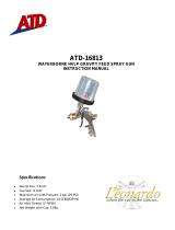
H8225 Inventory ............................... Qty
A. Paint Tank 2
1
⁄2 Gallon ......................... 1
B. Lid ........................................................ 1
C. Regulator Assembly ............................ 1
D. Spray Gun ........................................... 1
E. Material Hose ...................................... 1
F. Air Hose ............................................... 1
G. Wrench ................................................ 1
H. Cleaning Brush .................................... 1
I. Barbed Compression Hose Fitting ....... 1
J. Compression Nut
1
/4" NPT ................... 1
K. Lift Handle ........................................... 1
Inventory
SETUP
Figure 1. Model H8225 Inventory.
F
A
E
J
I
B
C
D
G
H
K
Your paint tank was carefully packaged for
safe shipping. If you discover any damage
after you have signed for delivery, immedi-
ately call Customer Service at (570) 546-
9663 for advice.
Save the containers and all packing materi-
als for possible inspection by the carrier or
its agent. Otherwise, filing a freight claim
can be difficult.
When you are completely satisfied with
the condition of the shipment, you should
inventory the contents.
Unpacking

Model H8225 2
1
⁄2 Gallon Paint Tank with Gun -6-
Tank Assembly
To assemble the paint tank:
1. Apply Teflon tape to all male pipe
threads.
2. Thread the lift handle into the center
hole on the tank lid (see Figure 2) and
secure with the hex nut.
3. Thread the regulator assembly onto the
swivel adapter on the lid, as shown in
Figure 2.
4. Connect a
1
/4" NPT air supply hose
(not included) to the inlet fitting on the
regulator.
5. Attach the air hose to the air outlet fit-
ting.
6. Connect the material hose to the fluid
outlet adapter on the tank lid.
7. Install a pressure regulator (not includ-
ed), between the tank regulator, (Figure
3) and the spray gun, since some of the
pressurized air from the compressor
will bypass the tank regulator.
Figure 3 depicts the paint tank con-
nected to a compressed air system with
a filter/regulator unit and a spray gun.
The filter/regulator unit protects your
tool from damaging water build-up,
and allows you to adjust and maintain
regulated air pressure. If you plan on
installing a filter/regulator unit in your
compressed air system, follow the con-
nection instructions with the unit.
Regulator Assembly
Fluid Outlet Adapter
Lift Handle
Figure 2. Regulator and lift handle installed on paint tank.
Figure 3. Paint tank connect to air compressor and spray gun.
Pressure Gauge
Air Inlet Fitting
Safety Valve
Air Outlet Fitting

-7-Model H8225 2
1
⁄2 Gallon Paint Tank with Gun
Spray Gun Assembly
Prior to assembly and use of the spray gun,
thoroughly clean and dry all parts. Please
Refer to Cleaning in the MAINTENANCE
section on Page 13 for more detailed
instructions.
Make sure all connections are tight enough
to prevent air leaks but not so tight as to
damage the tool.
1. Fluid Control: Controls the volume of
material that travels through the fluid
tip.
Air Hose
Material Hose
Figure 4. Material and air hoses attached to the spray gun.
Pattern Control
Atomizing Cap
Trigger
Fluid Control
Controls
2. Pattern Control: Adjusts the spray
pattern from a round pattern to a wide
fan.
3. Air Flow Control: Controls the fluid
pressure inside the spray gun.
4. Atomizing Cap : Controls the spray
pattern from vertical to horizontal.
5. Trigger : Two stage trigger. Stage
one only releases compressed air for
blowing off the work piece. Stage two
sprays material.

Model H8225 2
1
⁄2 Gallon Paint Tank with Gun -8-
OPERATIONS
The pressure regulator on the paint tank
controls the amount of pressure in the
paint tank and the spray gun.
The following are operating guidelines for
internal and external spray guns:
Internal Mix Guns: Use higher tank
pressures up to the full amount of air
pressure being delivered to the spray gun.
However, do not exceed 50 PSI at the
spray gun or in the paint tank.
External Mix Guns: Use lower tank
pressures—approximately 12 PSI for most
external mix guns. Start with the tank at
"zero" pressure and increase pressure
gradually until the correct spray pattern is
achieved.
Tank Regulator
Do not exceed the 50 PSI maximum
operating pressure on your paint tank.
Exceeding the maximum pressure
may cause the tank to explode,
causing serious personal injury.
EXPLOSION HAZARD! DO NOT
smoke or have any source of flame
or spark near spraying. Vapors will
explode if ignited.
RESPIRATORY HAZARD! Always use
a NIOSH approved respirator when
using spray equipment. Failure to
protect your lungs can lead to respi-
ratory illness and nervous system
damage. Spraying some paints and
varnishes may require a supplied air
respirator system.
TOXIC FUMES! Always use an
approved spray booth or well ven-
tilated area when spraying. NEVER
spray in an confined space where
toxic fumes and flammable vapors
can accumulate to deadly levels.

-9-Model H8225 2
1
⁄2 Gallon Paint Tank with Gun
Read the manual before operation.
Become familiar with this tool, its
safety instructions, and its operation
before beginning any work. Serious
personal injury may result if safety
or operational information is not
understood or followed.
Like all tools there is potential danger
when operating this tool. Accidents
are frequently caused by lack of
familiarity or failure to pay attention.
If normal safety precautions are
overlooked or ignored, serious
personal injury may occur.
To use your paint tank and spray gun:
1. Thoroughly mix and strain your paint
to remove undissolved particles that
could block the flow of material to the
gun.
2. Pour paint into the tank; or set a one
gallon can of paint in the tank, making
sure the lid's fluid tube is seated in the
can.
3. Place the lid assembly on the tank and
evenly hand tighten the lid clamp wing
screws.
4. Adjust the regulator at your air com-
pressor to 50 PSI.
5. Fully turn the regulator T-handle coun-
terclockwise to shut the tank regulator
OFF.
6. Connect the paint tank to the air com-
pressor.
7. Adjust the paint tank to 25 PSI on the
tank pressure gauge. Normal operating
pressure is 25-30 PSI. Using trial and
error, adjust the paint tank as neces-
sary between this range for optimum
results.
8. Adjust the regulator at the spray gun.
9. Start by testing the spray gun at a low
setting, then increase the air pressure
as needed for satisfactory results.
Tank Setup
This paint tank is not designed for
use with highly abrasive, corrosive,
or rust inducing materials. If such
materials are used, frequently and
thoroughly clean all components to
reduce the need to replace parts.
NOTICE

Model H8225 2
1
⁄2 Gallon Paint Tank with Gun -10-
The Model H8225 siphon feed spray gun
set is designed to spray a wide variety
of materials such as lacquers, stains,
primers, multi-component paints, clear
coats, acrylics, epoxies etc. It is ideal for
auto body and woodworking projects.
To use your spray gun:
1. Read and follow the material manufac-
turer's instructions for spraying, mixing,
safety, disposal, and any other instruc-
tion on the label or Material Safety Data
Sheet (MSDS).
2. Ensure the tank and hoses are secure-
ly tightened and all other fittings are
secure to avoid air leaks or material
spills.
3. Set the inlet air pressure (the air com-
ing to the spray gun) to the lowest
pressure recommended or to the mate-
rial manufacturer's recommendations.
4. Adjust the atomizing cap to vertical or
horizontal. See Atomizing Cap and
Fan Adjustments on Page 11 for fur-
ther explanation.
5. Fill the tank with material.
6. Test your material flow and spray pat-
tern on a piece of cardboard or scrap
material similar to your project. Trial
and error are necessary to achieve the
results you want.
Spraying
7. Adjust the fluid control knob to start
with a low volume of material and keep
the atomization as low as possible.
You will need to use a combination of
fluid control, inlet air pressure, air flow
control and stroke speed to achieve the
results you want. Spray so the material
wets out nicely without running or sag-
ging.
8. Use the pattern control knob to adjust
the spray fan to your desired pattern.
9. Keep the gun tip perpendicular to the
ground, parallel to the surface and
6-12" from the work at all times when
spraying, as shown in Figure 5. Do not
bend your wrist. This will cause the gun
to arc across the surface and distribute
the material unevenly, possibly creat-
ing sags and dry spots.
6"
12"
Figure 5. Spray technique.
10. Begin spraying 2-3 inches before the
work and continue to the end of the
work. Continue the motion for a few
inches past the work until you are
ready for the return stroke.
11. Maintain an even speed when spray-
ing.

-11-Model H8225 2
1
⁄2 Gallon Paint Tank with Gun
12. Overlap each stroke by 50%. This will
ensure even coverage as shown in
Figure 6. Overlapping less than 50%,
as shown in the figure to the right,
may lead to missed spots or streaky
results.
13. The spray stroke should have even con-
sistency and parallel edges. If it doesn't,
please refer to Troubleshooting on
Page 15.
CONTAMINATION HAZARD! Dispose
of paint waste in a responsible man-
ner! Follow manufacturer's recom-
mendations and local laws regarding
disposal.
6"
12"
Figure 6. Overlap technique.
No
Yes
The atomizing cap needs to be adjusted
for horizontal or vertical spraying patterns,
as shown in Figures 7 and 8 Spraying in
the wrong direction may lead to material
build up on the atomizing cap horn. Many
performance problems are caused by
clogged atomizing holes on the atomizing
cap horns (see Cleaning on Page 13).
Atomizing Cap and
Fan Adjustments
Stroke
Holes
Figure 7. Set up for horizontal stroke
direction with vertical fan pattern.
Figure 8. Set up for vertical spray stroke
with horizontal fan pattern.
Stroke
Holes
Figure 9. Fan adjustment.
Rotating the pattern adjustment control will
give you a range between the two patterns
in Figure 9.
Holes

Model H8225 2
1
⁄2 Gallon Paint Tank with Gun -12-
CLEANING AND LUBRICATION
3. Turn the tank regulator T-handle coun-
terclockwise until you no longer feel
spring tension.
4. Loosen the wing screws on the tank lid
(Figure 10), tip the clamps back, and
tip the tank lid to one side.
5. Loosen the spray gun atomizing cap
retaining ring about three turns, then
turn ON the gun air supply.
6. Cover the cap with a cloth and pull
the trigger to force the material back
through the hose and into the tank.
7. Empty and clean the tank of all paint,
and fill it with solvent.
8. Replace the lid, tighten the clamps,
and spray the gun until it sprays clean
solvent.
Note: Check with local laws regarding
this practice. If you are spraying on a
regular basis, spraying solvents into
the air may be illegal. A cabinet style
spray gun cleaner may be required.
9. Use solvent to thoroughly rise all part
that came in contact with the material,
then dry with compressed air or let air
dry.
10. Make sure all the fittings on the tank
and regulator, valve, and material hose
are free of hardened material that
could prevent free movement of air.
Proper cleaning is the best way to ensure
trouble free performance from your paint
tank. If your tank is not thoroughly cleaned,
damage and poor operation will result.
Problems caused by improper cleaning will
not be covered by the warranty. Clean the
tank immediately after each use.
To clean your paint tank:
1. DISCONNECT THE AIR SUPPLY
FROM THE TANK!
EXPLOSION HAZARD! Removing the
lid while the tank is pressurized could
result in lid being thrown violently
from tank, causing serious personal
injury. Always shut off air pressure
at source and bleed off all pressure
in tank before removing lid.
2. Bleed out all tank pressure by pulling
the ring on the safety valve (Figure 10)
until air stops hissing out.
Cleaning the Tank
Figure 10. Safety valve ring.
Safety Valve
Ring
Wing Screw
Clamp

-13-Model H8225 2
1
⁄2 Gallon Paint Tank with Gun
Proper cleaning is the best way to ensure
trouble free performance from your spray
gun. If your gun is not thoroughly cleaned,
damage and poor spraying will result.
Problems caused by improper cleaning will
not be covered by the warranty. Clean the
spray gun immediately after each use.
To clean your spray gun:
1. Spray a small amount of solvent
through the spray gun.
Note: Check with local laws regarding
this practice. If you are spraying on a
regular basis, spraying solvents into
the air may be illegal. A cabinet style
spray gun cleaner may be required.
2. DISCONNECT THE GUN FROM THE
COMPRESSED AIR!
3. Disconnect the gun from the material
hose.
4. Disassemble the gun by unscrewing
the fluid control knob, then remove the
spring and needle.
5. Unscrew the atomizing cap and the
fluid tip. The fully disassembled gun
should look like Figure 11.
6. Rinse these parts thoroughly in sol-
vent, then dry with compressed air or
let air dry.
Note: If the small holes in the atomiz-
ing cap become blocked, soak in clean
solvent. If the blockage still exists,
clear the blockage with a small needle,
taking great care to not enlarge or
damage the hole. Damage to the hole
will create a disrupted spray pattern.
7. Use the cleaning brush with solvent to
clean the inner orifice and other hard
to reach areas on the outside of the
spray gun body.
8. Wipe the gun body with a lint free shop
towel to dry.
DO NOT soak the spray gun body in
solvent. Prolonged exposure to sol-
vent will rapidly deteriorate the spray
gun washers and seals. Ignoring this
notice will void your warranty.
NOTICE
EXPLOSION HAZARD! Chlorinated
Solvents like 1,1,1-Tricloroethane
and Methylene Chloride (methyl
chloride) can chemically react with
aluminum and may explode. Many
parts in spray guns are made of alu-
minum. Read solvent label carefully
before using solvent.
Cleaning the Spray
Gun
Figure 11. Disassembly for cleaning.
Atomizing Cap
Fluid Tip
Spring
Fluid Control Knob
Needle
Seal

Model H8225 2
1
⁄2 Gallon Paint Tank with Gun -14-
Spray Gun Lubrication
Lubricate the following areas with a non-
silicon spray gun lubricant after cleaning.
A. Atomizing Cap Threads
B. Air Valve Packing
C. Trigger Pin
D. Pattern Control
E. Fluid Control Knob
Allow the lubricant to coat threads, and run
into gun body to lubricate all moving parts
and seals.
Figure 12. General lubrication points.
A
B
C
D
E

-15-Model H8225 2
1
⁄2 Gallon Paint Tank with Gun
Tank Troubleshooting
Symptom Possible Cause Solution
Air escaping from
regulator port.
1. Broken or damaged dia-
phragm in tank regulator.
1. Replace tank regulator.
Pressure dropping
slowly on regulator.
1. Dirty or worn valve seat in
regulator.
2. Loose air fittings leaking air.
1. Replace tank regulator.
2. Tighten loose air fittings or
remove and re-install with
new Teflon tape.
Fluid or air leak at
lid gasket.
1. Defective lid gasket.
2. Wing screw loose.
3. Dirt or foreign object between
gasket and rim.
1. Replace lid gasket.
2. Tighten wing screws
evenly.
3. Clean rim and gasket.
Paint tends to settle
rapidly in tank.
1. Paint not mixed or thinned suf-
ficiently.
1. Mix or thin paint according
to manufacturer's instruc-
tions.
Gauge not register-
ing air pressure.
1. Air pressure turned OFF.
2. Defective pressure gauge.
1. Turn air pressure ON.
2. Replace pressure gauge.
Safety valve pop-
ping out.
1. Tank pressure too high.
2. Defective safety valve.
1. Reduce tank pressure to
25-30 PSI (See Page 8).
2. Replace safety valve.

Model H8225 2
1
⁄2 Gallon Paint Tank with Gun -16-
Spray Gun Troubleshooting
Symptom Possible Cause Solution
Fluttering or spitting
spray.
1. Dry or worn fluid tip seat per-
mits air to seep into fluid pas-
sage.
2. Material level too low.
3. Fluid tip or filter obstructed.
4. Dry needle packing.
1. Tighten fluid tip or replace
seat with new one.
2. Add material.
3. Clean.
4. Lubricate needle.
Uneven top or bot-
tom pattern.
1. Atomizing cap holes are
obstructed.
2. Build-up on top or bottom of
fluid tip.
3. Build-up on atomizing cap is
on needle seat.
1. Clear holes.
2. Clean.
3. Clean.
Right or left arc
pattern.
1. Left or right side horn holes
are plugged.
2. Build-up on left or right side of
fluid tip.
3. Build-up of material inside
atomizing cap.
1. Clear holes.
2. Clean.
3. Clean.
Heavy deposit of
material in center.
1. The material flow exceeds the
atomizing cap capacity.
2. Inlet air pressure is too low.
3. Material is too thick.
1. Lower fluid flow.
2. Increase inlet air pressure.
3. Thin material.
Narrow center pat-
tern.
1. Volume control turned in too
far.
2. Inlet air pressure too high.
3. Fluid pressure is too low.
4. Material is too thin.
1. Increase volume.
2. Reduce inlet air pressure.
3. Increase fluid pressure.
4. Adjust material.
No spray output. 1. No pressure at gun.
2. Fluid passages dirty.
3. Fluid control closed.
4. Out of paint.
5. Material too thick.
1. Check air supply.
2. Clean gun, remove any
obstructions.
3. Open.
4. Refill.
5. Thin to manufacturer's rec-
ommendations.

-17-Model H8225 2
1
⁄2 Gallon Paint Tank with Gun
Symptom Possible Cause Solution
Excessive over-
spray.
1. Fluid pressure too high.
2. Gun is too far from surface.
3. Spraying too fast.
1. Reduce fluid pressure.
2. Keep gun at recommended
distance.
3. Slow down and maintain
consistent, even parallel
stroke.
Unable to control
spray fan.
1. Pattern adjustment screw is
not seating properly.
2. Atomizing cap is loose.
1. Clean or replace.
2. Tighten atomizing cap.
Runs and sags. 1. Damaged seal. 1. Replace damaged seals.
Material leaks from
gun.
1. Fluid tip loose.
2. Dry or damaged seals.
3. Excessive pressure.
1. Tighten.
2. Replace seals.
3. Reduce pressure.
Thick dimpled fin-
ish: orange peel
appearance.
1. Holding gun too close to sur-
face.
2. Inlet air pressure too low.
3. Material not properly mixed.
4. Surface is dirty or oily.
1. Spray at recommended dis-
tance.
2. Check inlet air pressure.
3. Follow manufacturer's
instructions.
4. More surface prep is
required.
Dry Spray. 1. Inlet air pressure too high.
2. Gun too far from surface.
3. Gun stroke too fast.
1. Lower inlet air pressure.
2. Keep gun at recommended
distance.
3. Slow down and maintain
consistent even parallel
stroke.
Gun leaks from
fluid tip.
1. Debris will not let the needle
seat with the fluid tip.
1. Clean or replace both.
Contaminated
paint: fish eye
appearance.
1. Water or oil in the air line. 1. Install an in-line air filter.
2. Replace air line.

Model H8225 2
1
⁄2 Gallon Paint Tank with Gun -18-
H8225 PAINT TANK
1
2
3
4
5
6
7
8
9
10
11
12
13
14
15
16
17
18
19
20
21
22
15
15
23
24
25
26
27
12-1
REF PART # DESCRIPTION REF PART # DESCRIPTION
1 PH8225001 FLUID OUTLET ADAPTER 14 PH8225014 GAUGE
2 PH8225002 FLUID TUBE 15 PH8225015 ADAPTER
3 PH8225003 HINGE PIN 16 PH8225016 LID ASSEMBLY
4 PH8225004 COTTER PIN 17 PH8225017 LID GASKET
5 PH8225005 LID CLAMP 18 PH8225018 TANK SHELL ASSEMBLY
6 PH8225006 WING SCREW M10-1.5 X 40 19 PH8225019 MATERIAL HOSE
7 PH8225007 FLUID OUTLET ADAPTER 20 PH8225020 AIR HOSE
8 PH8225008 HEX NUT M8-1.25 21 PH8225021 BARBED HOSE FITTING
9 PH8225009 HANDLE M8-1.25 22 PH8225022 COMPRESSION NUT 1/4" NPT
10 PH8225010 SAFETY VALVE 23 PH8225023 WARNING ID LABEL
11 PH8225011 T-BRANCH 24 PH8225024 READ MANUAL LABEL-VERT.
12 PH8225012 SWIVEL ADAPTER 25 PH8225025 RESPIRATOR/GLASSES LABEL
12-1 PH8225012-1 THREADED FITTING 18MM-1.5 26 PH8225026 MAXIMUM PRESSURE LABEL
13 PH8225013 REGULATOR 27 PH8225027 DEPRESSURIZE LABEL
/