Trane BAYLOAM105A Installation guide

Category
Heat pumps
Type
Installation guide

This manual is also suitable for

Trane BAYLOAM105AA is a low ambient control kit designed to enhance the performance of compatible Trane air conditioning and heat pump units in low-temperature conditions. It includes a control module, liquid line sensor, outdoor air sensor, universal bracket, solid-state relay, and installation hardware. The kit helps maintain optimal system operation and prevents damage to the compressor in low-ambient environments by controlling the activation of the compressor crankcase heater.

Trane BAYLOAM105AA is a low ambient control kit designed to enhance the performance of compatible Trane air conditioning and heat pump units in low-temperature conditions. It includes a control module, liquid line sensor, outdoor air sensor, universal bracket, solid-state relay, and installation hardware. The kit helps maintain optimal system operation and prevents damage to the compressor in low-ambient environments by controlling the activation of the compressor crankcase heater.

ALL phases of this installation must comply with NATIONAL, STATE AND LOCAL CODES
IMPORTANT — This Document is customer property and is to remain with this unit. Please return to service information
pack upon completion of work.
HAZARDOUS VOLTAGE - DISCONNECT POWER BEFORE SERVICING
WARNING:
© Trane 2008
Installer’s Guide
18-HD62D1-6
Low Ambient Control Kit
Identify Low Ambient Kit Contents
Refer to Figure 1 on page 2 to identify the kit compo-
nents.
Inspect Contents
You must report damage and make claims to the
transportation company immediately. Report missing
parts to your supplier immediately and replace with
authorized parts only.
NOTE: Units operating in low ambient conditions require com-
pressor crankcase heaters due to changes in head pressure.
Refer to Table 1 for the appropriate crankcase heater accessory
number. Install the heater before operating the low ambient con-
trol.
BAYLOAM105AA
Model:
Install BAYLOAM Kit
1. Disconnect and verify that power is off.
2. Remove Access Panels
Remove these four (4) access panels (see
Figure 2, page 2):
Control/Heat box access panel
Blower access panel
Compressor access panel
Coil access panel
3. Mount Control Module
The Control Module is to be mounted to the universal
bracket (included in the kit) or the Compressor Startkit
bracket, depending upon your unit's configuration.
Continue with the following section that applies to your
configuration:
3a. 230 Volt 2/4WC** with Compressor Start Kit,
460 Volt 2/4WC*3060A4 & 460 Volt 4WCZ6 units.
Go to page 3.
3b. 230 Volt Single Phase 2/4WC** units WITH-
OUT Start Kit, All 4TC** units & 230/460 Volt
Three Phase 2/4WC** units except for 2/
4WC*3060A4 & 460 Volt 4WCZ6 units. Go to page
4.
3c. 230 Volt 2/4YC** and 4DC** units with
Compressor Start Kit, 460 Volt 2/4YC*3060A4, &
460 Volt 4YCZ6 units. Go to page 5.
3d. 230 Volt 2/4YC** & 4DC** Single Phase units
WITHOUT Start Kit & 230/460 Volt Three Phase
2/4YC** & 4DC** units except 460 Volt 2/
4YC*3060A4, & 460 Volt 4YCZ6 units. Go to page 6.
For this Unit Use this Heater
4WC*3018, 2WC*3024-030,2WC*3048,
4YC*3018, 2YC*3024-030, 2YC*3042-048,
4TC*3018-024, 4WCY4024-030, 4TCY4024-
030, 4YCY4024-030, 4DCY4024-030 (230V)
BAYCCHT101AA
(Reciprocating)
(65 Watts)
2WC*3036-042, 2WC*3060, 4WC*3036-060,
2YC*3036, 4YC*3036-060, 2YC*3060,
4TC*3030-060, 4YCY4036-060, 4WCY4036-
060, 4TCY4036-060,4DCY4036-060,
4WCZ6036-060, 4YCZ6036-060,
4DCZ6036-060 (230V)
BAYCCHT102AA
(Scroll)
(60 Watts)
4WC*3036-060, 4YC*3036-060, 4TC*3036-060,
4WCZ6036-060, 4YCZ6036-060 (460V)
BAYCCHT404BA
(Scroll)
(60 Watts)
Table 1. Crankcase Heater Accessory Numbers
2
Installer’s Guide
Figure 2. Identify Exterior Components
Compressor
Access Panel
Blower Access
Panel
Control/Heat
Box Access
Panel
4 Louvered Panels
(1 on each side)
Figure 1. Identify LOAM Kit Components
Note: Unit vents not
shown
Universal Bracket
Liquid Sensor Clamp
Bushing
Wire Nuts (5)
Cable Ties (5)
Liquid Sensor
Assembly
Thermal
Compound
Outdoor
Air Sensor
Retainer
Dart
Information
Label
Press Tight Insulating Tape
(sensor Insulation)
Low Voltage
Pigtail Assembly
Sheet Metal
Screw (5)
Outdoor Air Sensor
Control Module
Solid State
Relay (SSR)
Coil/Filter Access
Panel
3
Installer’s Guide
3a. 2/4WC** Units
230 Volt 2/4WC** with Compressor Start Kit &
460 Volt 2/4WC*3060A4 & 460 Volt 4WCZ6 units
1. Remove the Control Module from the Universal Bracket
(remove 2 machine screws).
2. Mount the Control Module to the Compressor Start Kit
bracket using the two (2) machine screws. See Figure 3.
3. Continue with step 4. Mounting the Liquid Line Sensor,
page 7.
Figure 3. 230 Volt 2/4WC** with Compressor Start Kit & 460 Volt 2/4WC*3060A4 & 460 Volt 4WCZ6 units
Start Kit
Bracket
Mount Control
Module
to Start Kit Bracket
Using Two Machine
Screws.
Compressor
Start Kit
Control Module
SSR
460v Transformer is
mounted in place of
Start Kit for 460 volt
2/4WC*3060A4 &
4WCZ6 units
4
Installer’s Guide
3b. 2/4WC** and 4TC** Units
230 Volt Single Phase 2/4WC** units WITHOUT
Start Kit, All 4TC** units & 230/460 Volt Three
Phase 2/4WC** Units except for 2/4WC*3060A4 &
460 Volt 4WCZ6 units
Note: Use the Universal Bracket shipped in the Low
Ambient kit. Mount the Control Module to the Universal
Bracket as needed so that the assembly matches the
illustration below.
Figure 4. 230 Volt Single Phase 2/4WC** units WITHOUT Start Kit, All 4TC** units &
230/460 Volt Three Phase 2/4WC** units except for 2/4WC*3060A4 & 460 Volt 4WCZ6 units
Mount Universal
Bracket to back
wall of Control Box
with two (2)
Sheetmetal Screws
(horizontally)
Control Box
Mount Universal
Bracket to Control
Box with one (1)
Sheetmetal Screw
(vertically)
Control
Module
Universal
Bracket
1. Mount the Control Module and Universal Bracket assembly
bracket to the back of the control box with two (2)
sheetmetal screws inserted horizontally. Also, mount the
Universal Bracket to the bottom of the control box with one
(1) sheetmetal screw inserted vertically.See Figure 4.
2. Continue with step 4, Mounting the Liquid Line Sensor,
page 7.
5
Installer’s Guide
3c. 2/4YC** and 4DC** Units
230 Volt 2/4YC** and 4DC** units with Compres-
sor Start Kit, 460 volt 2/4YC*3060A4, & 460 volt
4YCZ6 units
1. Remove the Control Module from the Universal Bracket (2
machine screws).
2. Then, align the two holes in the ControlModule with the
two clearance holes in the Start Kit bracket.
Figure 5. 230 Volt 2/4YC** and 4DC** units with Compressor Start Kit,
460 volt 2/4YC*3060A4, & 460 volt 4YCZ6 units
3. Mount the Control module to the Start Kit bracket with the
two (2) machine metal screws you removed from the
Universal Bracket. See Figure 5.
Continue with step 4, Mounting the Liquid Line Sensor, page 7.
Compressor
Start Kit
Start Kit
Bracket
Mount Control Module
to Start Kit Bracket
Using Two Sheetmetal
Screws
Control
Module
460v Trans-
former is
mounted in
place of Start
Kit for 460 Volt
2/4YC*3060A4
& 460 Volt
4YCZ6 units
6
Installer’s Guide
3d. 2/4YC** and 4DC** Units
230 Volt 2/4YC** & 4DC** Single Phase units
WITHOUT Start Kit & 230/460 Volt Three Phase 2/
4YC** & 4DC** units except 460 Volt 2/
4YC*3060A4, & 460 Volt 4YCZ6 units
Note: Use the Universal Bracket shipped in the Low
Ambient kit. Mount the Control Module to the Universal
Bracket as needed so that the assembly matches the
illustration below.
1. Mount the Control Module and Universal Bracket
assembly to the bottom of the control box with two
(2) sheetmetal screws. One is inserted horizontally
from inside the control box into the universal
bracket, and one is inserted vertically . See Figure
6.
Figure 6. 230 Volt 2/4YC** & 4DC** Single Phase units WITHOUT Start Kit &
230/460 Volt Three Phase 2/4YC** & 4DC** units except 460 volt 2/4YC*3060A4, & 460 volt 4YCZ6 units
Mount Universal
Bracket to back
wall of Control
Box Using one
(1) Sheetmetal
Screw
(Horizonally).
Control
Module
Universal
Bracket
Mount Universal
Bracket to Control
Box using one (1)
Sheetmetal Screw
(vertically)
Control Box
2. Continue with step 4, Mount the Liquid Line
Sensor, page 7.
7
Installer’s Guide
6. Route the Sensor Leads
In this step you route the outdoor sensor leads to
the Control Box.
1. Route the outdoor temperature sensor lead wires
down to the intermediate top and then under the
outdoor coil. See Figure 9, page 8. You may need to
lift the coil slightly to slide the sensor lead wires
under the coil.
2. Route the outdoor temperature sensor leads down
into the compressor compartment through the one
(1") hole. See Figure 9. Using a wire tie from the
kit, tie the leads to the existing wiring at the point
where the leads go through the sheet metal
opening. Ensure that the leads DO NOT lie
across the sharp sheet metal edges of the
openings.
3. Continue to route the sensor leads through
the compressor compartment, through the
partition, and into the Blower compartment. From
the Blower compartment, continue to route the
leads into the Control Box. Use wire ties to
secure the leads to the existing wires. This
ensures that any wiring is kept away from
the blower and sharp sheet metal.
4. In the Control Box, route the sensor leads to the
Control Module. You make the connections later.
5. Reinstall the outdoor fan assembly with the eight
(8) screws and screw caps you removed in the
Mount the Liquid Line Temperature Sensor section.
6. To make your connections, continue with step 7
Connect Module Wires, page 9.
5. Mount the Outdoor Temperature Sensor
In this step you attach the outdoor sensor to the
outside of the outdoor coil. See Figure 9, page 8.
1. On the outdoor fan grill, remove eight (8) plastic
screw caps covering the fan screws. Then, remove
the eight (8) screws that secure the outdoor fan grill
to the top of the unit. See Figure 8. Remove the fan
assembly and place it on top of the unit with the fan
blades facing up.
2. Remove the back outdoor coil louvered panel to
access the outer surface of the outdoor coil:
a.) Remove the three (3) screws across the top of the
panel.
b.) Lift or slide the panel up enough to unhook it
from the slots in the unit.
4. Mount the Liquid Line Temperature Sensor
In this step you mount the liquid line sensor to the
liquid line. See Figure 7.
1. Attach the liquid line temperature sensor to the
liquid line above the TXV as follows.
a.) Apply thermal compound (provided in kit) to an
area on the liquid line where you are mounting
the sensor. See Figure 7.
b.) Use the clamp (provided in kit) and attach the
sensor to the liquid line. See Figure 7.
c.) Wrap the sensor with insulating tape (provided
in kit).
2. Route the sensor wires through the compressor
area, past the blower and into the Control Box. See
Figure 9, page 8.
Figure 7. Liquid Line Temperature Sensor Location
Continue with step 6. Route the Sensor Leads.
Insert Dart End into
Coil
Attach Air Sensor to
Clip on Retainer Dart
3. Insert the retainer into the outside surface of the
spine-fin coil about half way up the outside surface
of the coil. Attach the outdoor air sensor to the clip
on the outdoor air sensor retainer dart. See Figure
8 below and Figure 9, page 8.
Figure 8. Mount Outdoor Air Sensor
Continue with step 5. Route the Sensor Leads.
8
Installer’s Guide
Figure 9. Mount Outdoor Temperature Sensor
OUTDOOR
TEMPERATURE
SENSOR DART
OUTDOOR
TEMPERATURE
SENSOR WIRES
LIQUID LINE
SENSOR WIRES
LOUVERED PANEL REMOVE 3 SCREWS
LIFT PANEL UP TO UNHOOK FROM SLOT
REMOVE 8 FAN GRILL SCREWS
TO ROUTE OUTDOOR SENSOR WIRES
BEHIND COIL INTO COMPRESSOR AREA
9
Installer’s Guide
Figure 10. 2/4YC** and 4TC** Single Phase 230 Volt Cooling and Gas/Electric Models
7. Connect Control Module Wires
There are five (5) Control Module wiring configura-
tions. Depending on your configuration continue with
the section that applies.
7a. 2/4YC** and 4TC** Single Phase 230 Volt
Cooling and Gas/Electric Models. Go to page 9.
7b. 2/4WC** & 4DC** Single Phase 230 Volt
Heat Pump Models. Go to page 10.
7c. 2/4YC** and 4TC** Three Phase 230 & 460
Volt Cooling and Gas/Electric Models. Go to page
11.
7d. 2/4WC** & 4DC** Three Phase 230 Volt
Heat Pump Models. Go to page 12.
7e. 2/4WC** Three Phase 460 Volt Heat Pump
Models. Go to page 13.
7a. 2/4YC** and 4TC** Single Phase 230 Volt Cooling
and Gas/Electric Models. See Figure 10.
Disconnect the black fan motor lead from the
contactor (this wire is attached to contactor terminal
“L2”, with a quick connect terminal). Cut the
terminal off of this wire and strip the end about 1/2
inch. Select one of the black wires from the SSR relay
on the Control Module, cut the terminal off and strip
the end about 1/2 inch. Connect these two (the black
fan motor lead to the black SSR lead) with a wire nut
supplied.
Connect the other black wire from the solid state
relay (SSR) to the contactor terminal “L2” (from
where the fan motor lead was disconnected).
Connect Low voltage wires (BYO):
1. Connect the 3-pin BYO low voltage wire harness
(supplied in kit) to J5 on the Control Module (3-pin
male connector). See Figure 11. Note: to ease the
insertion of the connector housing on to the J5
header, place the connector on the tips of the three
header pins. Angle the connector upward toward
the header latch while pushing connector over the
header pins.
2. Connect the yellow lead wire of the harness to a
¼ " male tab on the right hand side of the main
contactor (low voltage contactor coil terminal).
3. Connect the blue lead wire of the harness to the
wire nut junction of the blue wire (use new wire
nuts from kit).
4. Connect the orange wire to the wire nut junction
of the yellow wire (use new wire nuts from kit).
5. Connect the Liquid Line Sensor to J2 on the Con-
trol Module. See Figure 11 on page 10.
6. Connect the Outdoor Temperature Sensor (Ambi-
ent Sensor) to J3 on the Control Module. See Fig-
ure 11 on page 10.
7. Reinstall louvers and panels. Continue with step 8.
System Setup, Page 14.
IMPORTANT — Retain this wiring diagram; please return this document to service information pack upon completion of work.
10
Installer’s Guide
Figure 12. 2/4WC** & 4DC** Single Phase 230 Volt Heat Pump Models
7b. 2/4WC** & 4DC** Single Phase 230 Volt Heat
Pump Models. See Figure 12.
Disconnect and remove the black lead from the De-
frost Board relay to the "L2" terminal of the contactor
(the black wire is attached to the “COM” terminal of
the relay). Firmly hold relay when removing wire.
Connect one of the black leads from the (SSR) on the
Control Module to the position on the unit contactor
"L2" (where the previous wire was removed). Connect
the other black lead on the (SSR) on the Contoller
Module to the "COM" terminal on the Defrost Board.
Connect Low voltage wires (BYO):
1. Connect the 3-pin BYO low voltage wire harness
(supplied in kit) to J5 on the Control Module (3-
pin male connector). See Figure 11. Note: to ease
the insertion of the connector housing on to the J5
header, place the connector on the tips of the three
header pins. Angle the connector upward toward
the header latch while pushing connector over the
header pins.
2. Connect the yellow lead wire of the harness to a
¼ ” male tab on the right hand side of the main
contactor (low voltage contactor coil terminal). See
Figure 12.
3. Connect the blue lead wire of the harness to the
wire nut junction of the blue wire (use new wire
nuts in kit).
4. Connect the orange wire to the wire nut junction
of the orange wire (use new wire nuts from kit).
5. Connect the Liquid Line Sensor to J2 on the
Control Module. See Figure 11.
6. Connect the Outdoor Temperature Sensor (Ambi-
ent Sensor) to J3 on the Control Module.
7. Reinstall louvers and panels. Continue with step 8.
System Setup, page 14.
1
1 2 3 4
ON
ON
OFF
OFF
S2
S2
TEST
TEST
S1
S1
AMBIENT
AMBIENT
LIQUID
LIQUID
B Y O
ALERT
ALERT
Lite
Lite
Port
Port
RED
RED
LED
LED
GREEN
GREEN
LED
LED
S2-1,2,3,4
S2-1,2,3,4
DIP SWITCHES
DIP SWITCHES
S1
S1
TEST
TEST
SWITCH
SWITCH
AMBIENT
AMBIENT
SENSOR
SENSOR
(OUTDOOR
(OUTDOOR
TEMP SENSOR)
TEMP SENSOR)
LIQUID
LIQUID
LINE
LINE
SENSOR
SENSOR
B,Y,O
B,Y,O
J5
J5
J2
J2
J3
J3
Figure 11. Control Module Switches, Connectors, and LEDs
IMPORTANT — Retain this wiring diagram; please return this document to service information pack upon completion of work.
11
Installer’s Guide
7c 2/4YC** and 4TC** Three Phase 230 Volt Cooling
and Gas/Electric Models. See Figure 13.
Disconnect the black fan motor lead from the
contactor (this wire is attached to contactor terminal
“T2”, with a quick connect terminal). Cut the
terminal off of this wire and strip the end about 1/2
inch. Select one of the black wires from the SSR relay
on the Control Module, cut the terminal off and strip
the end about 1/2 inch. Connect these two ( the black
fan motor lead to the black SSR lead) with a wire nut
supplied.
Connect the other black wire from the SSR to the
contactor terminal “T2” (from where the fan motor
lead was disconnected).
Connect Low voltage wires (BYO):
1. Connect the 3-pin BYO low voltage wire harness
(supplied in kit) to J5 on the Control Module(3-pin
male connector). See Figure 14 on page 12. Note: to
ease the insertion of the connector housing on to the
J5 header, place the connector on the tips of the
three header pins. Angle the connector upward to-
ward the header latch while pushing connector over
the header pins.
2. Connect the yellow lead wire of the harness to a
¼ " male tab on the right hand side of the main
contactor (low voltage contactor coil terminal). See
Figure 13.
3. Connect the blue lead wire of the harness to the
wire nut junction of the blue wire (use new wire
nuts from kit).
4. Connect the orange wire to the wire nut junction
of the yellow wire (use new wire nuts from kit).
5. Connect the Liquid Line Sensor to J2 on the Con-
trol Module.See Figure 14 on page 12.
6. Connect the Outdoor Temperature Sensor (Ambi-
ent Sensor) to J3 on the Control Module.
7. Reinstall louvers and panels. Continue with step 8.
System Setup, Page 14.
Figure 13. 2/4YC** and 4TC** 230/460 volt Three Phase Cooling and Gas/Electric Models
IMPORTANT — Retain this wiring diagram; please return this document to service information pack upon completion of work.
12
Installer’s Guide
Figure 15. 2/4WC** & 4DC** Three Phase 230 Volt Heat Pump Models
7d. 2/4WC** & 4DC** Three Phase 230 Volt Heat
Pump and Dual Fuel Models. See Figure 15.
Disconnect and remove the black lead from the De-
frost Board relay to the "T2" terminal of the contactor
(the black wire is attached to the “COM” terminal of
the relay). Firmly hold relay when removing wire.
Connect one of the black leads from the (SSR) on the
Control Module to the position on the unit contactor
"T2" (where the previous wire was removed). Connect
the other black lead on the (SSR) on the Control
Module to the "COM" terminal on the Defrost Board.
Connect Low voltage wires (BYO):
1. Connect the 3-pin BYO low voltage wire harness
(supplied in kit) to J5 on the Control Module (3-
pin male connector). See Figure 14. Note: to ease
the insertion of the connector housing on to the J5
header, place the connector on the tips of the three
header pins. Angle the connector upward toward
the header latch while pushing connector over the
header pins.
2. Connect the yellow lead wire of the harness to a
¼” male tab on the right hand side of the main
contactor (low voltage contactor coil terminal). See
Figure 15.
3. Connect the blue lead wire of the harness to the
wire nut junction of the blue wire (use new wire
nuts in kit).
4. Connect the orange wire to the wire nut junction
of the orange wire (use new wire nuts from kit).
5. Connect the Liquid Line Sensor to J2 on the
Control Module. See Figure 14.
6. Connect the Outdoor Temperature Sensor (Ambi-
ent Sensor) to J3 on the Control Module.
7. Reinstall louvers and panels. Continue with step 8.
System Setup, page 14.
1
1 2 3 4
ON
ON
OFF
OFF
S2
S2
TEST
TEST
S1
S1
AMBIENT
AMBIENT
LIQUID
LIQUID
B Y O
ALERT
ALERT
Lite
Lite
Port
Port
RED
RED
LED
LED
GREEN
GREEN
LED
LED
S2-1,2,3,4
S2-1,2,3,4
DIP SWITCHES
DIP SWITCHES
S1
S1
TEST
TEST
SWITCH
SWITCH
AMBIENT
AMBIENT
SENSOR
SENSOR
(OUTDOOR
(OUTDOOR
TEMP SENSOR)
TEMP SENSOR)
LIQUID
LIQUID
LINE
LINE
SENSOR
SENSOR
B,Y,O
B,Y,O
J5
J5
J2
J2
J3
J3
Figure 14. Control Module Switches, Connectors, and LEDs
IMPORTANT — Retain this wiring diagram; please return this document to service information pack upon completion of work.
13
Installer’s Guide
Figure 16. 2/4WC** Three Phase 460 Volt Heat Pump Models
7e. 2/4WC** Three Phase 460 Volt Heat Pump Models
(see Figure 16)
Disconnect and remove the black lead from the fan
relay (terminal #1) to the unit contactor "T2". Connect
one black lead from the SSR on the Control Module to
the #1 terminal of the fan relay. Connect the other
black lead to the unit contactor "T2" terminal.
Connect Low voltage wires (BYO):
1. Connect the 3-pin BYO low voltage wire harness
(supplied in kit) to J5 on the Control Module (3-pin
male connector). See Figure 14. NOTE: to ease the
insertion of the connector housing on to the J5
header, place the connector on the tips of the three
header pins. Angle the connector upward toward
the header latch while pushing connector over the
header pins.
2. Connect the yellow lead wire of the harness to a
¼ " male tab on the right hand side of the main
contactor (low voltage contactor coil terminal). See
Figure 16.
3. Connect the blue lead wire of the harness to the
wire nut junction of the blue wire (use new wire
nuts in kit).
4. Connect the orange wire to the wire nut junction
of the orange wire (use new wire nuts from kit).
See Figure 16.
5. Connect the Liquid Line Sensor to J2 on the
Control Module. See Figure 14.
6. Connect the Outdoor Temperature Sensor (Ambi-
ent Sensor) to J3 on the Control Module.
7. Reinstall louvers and panels. Continue with step 8.
System Setup, page 14.
IMPORTANT — Retain this wiring diagram; please return this document to service information pack upon completion of work.
14
Installer’s Guide
minutes after Y is applied.
The liquid temperature set point will not change
during system start-up.
The dip switches should be set prior to initial
application of the Y signal to the Control Module.
The dip switches should be set for each specific
HVAC system based upon the following
instructions:
8c. Determine liquid temperature set point
Reference appropriate high side charging chart
for liquid pressure for cooling units and head
pressure for heat pump units.
Locate the high side pressure for 70 deg F
outdoor temperature at the expected indoor wet
bulb temperature in Table 2. Correct the high
side pressure according to the specific unit being
used. For Heat pumps subtract 7 psi, for cooling
only units subtract 0 (zero) psi. Using the
refrigerant properties chart, find the saturation
temperature for the calculated liquid pressure.
Subtract the anticipated sub-cooling temperature
(typically 12 degrees) from the saturation
temperature to obtain an estimate of the liquid
temperature. Set S2 dip switch 1, 2 and 3 settings
to the nearest liquid temperature set point in the
table below.
S2 Dip Switch 4: Off - Automatic Mode
(recommended setting)
On - Manual Mode
8b. Dip Switches (S2)
The Control Module will control a liquid
temperature set point as determined by the dip
switch settings. The dip switch is used:
1. To select either Automatic mode or Manual
Mode operation (S2 dip switch 4 setting).
2. To select the liquid temperature set point (S2
dip switch 1, 2 and 3 settings).
Automatic Mode (S2 dip switch 4 in “Off”
position) - The Control Module determines the
approach temperature based upon the liquid and
ambient temperature readings. The approach
temperature = liquid temperature – ambient
temperature. The approach temperature is
calculated only when the ambient temperature is
in the range of 65 to 75 deg F and the outdoor fan
is on continuously. If the Control Module has not
yet acquired an approach temperature, S2 dip
switch 1, 2 and 3 settings are used for
determining the liquid temperature set point the
same as in Manual Mode. If the Control Module
has acquired an approach temperature, then the
liquid temperature set point is determined as
follows:
Liquid Temperature Set Point = Approach
Temperature + 70 deg F
Manual Mode (S2 dip switch 4 in “On” position) -
The S2 dip switch 1,2,3 settings are read by the
Control Module and used to determine the liquid
temperature set point when:
1) Y is first applied,
2) After initial startup mode completion, during
the system control mode and no sooner than six
8. System Setup
The Control Module contains a momentary test
switch (S1) and a 4-position installer selectable
dip switch (S2). Both components are located in
the lower right hand corner of the Control
Module. See Figure 11 on page 10.
8a. Test Switch (S1)
The test switch provides a means of verifying that
the fan motor is under the control of the Low
Ambient Control Module. A "Y" signal must be
present in order to test the control. Depressing the
test switch causes the fan to alternately cycle on
(for 3 seconds) and off (for 3 seconds) for a total
time of 12 seconds. The on / off fan operation may
be observed by watching the fan once the test
function has been invoked or by monitoring the
head pressure using a gauge set. The LED on the
solid state relay should light when voltage is being
applied to the fan motor. Once the 12-second test
period is complete the control resumes normal
control operation.
LIQUID TEMP
SET POINT°F
DIP
SWITCH 1
DIP
SWITCH 2
DIP
SWITCH 3
70 °F OFF OFF OFF
76 °F OFF OFF ON
82 °F OFF ON OFF
88 °F OFF ON ON
94 °F ON OFF OFF
100 °F ON OFF ON
106 °F ON ON OFF
112 °F ON ON ON
Table 2. Liquid Temperature Set Point
8d. LEDs
The Control Module contains two LEDs, one
green and one red surface mount. See Figure 11
on page 10. The green LED is a status indicator
labeled Lite Port on the Control Module and
flashes at a ½ second on (plus fast blink at the
end for lite port data) and ½ second off rate in
the cooling mode. In the heating mode the green
15
Installer’s Guide
LED is full on with a blink/flicker OFF (LitePort
data transmission) every second.
The red LED is a small surface mount component
located near the end of the large capacitor. The
red LED is labeled ALERT on the Control Mod-
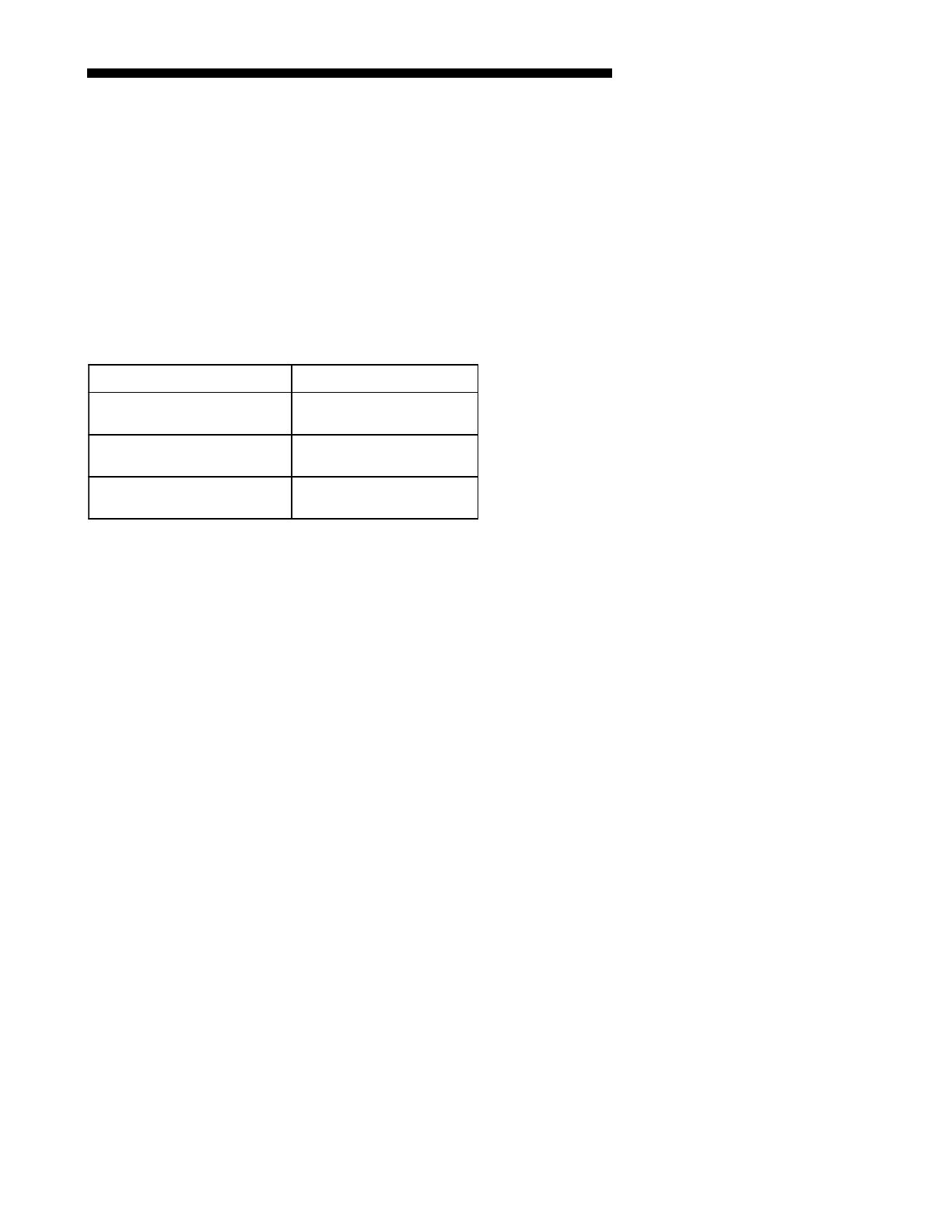
ule. The red LED indicator is normally off. If the
red LED is on or flashing then a fault is indicated
according to the following:
If the cause of a fault is cleared or repaired then
the red LED fault indication will clear with the
removal and reapplication of 24 VAC power (Y) to
the control.
Table 3. Control Module Red LED Status
Control Module SSR LED.
The solid state relay (SSR) on the Control Module
also contains a green LED indicator. This LED
indicates when the solid state relay is energized
by the control. If the control is cycling the fan then
this LED will be on/off accordingly.
9. Attach the Information label
Attach the Information Label to the Control Box
cover. This label identifies the fan motor cycling
during low ambient operation.
10. System Check-Out
10a. 2/4YC ** and 4TC** Units only
Verify that the Control Module is installed and
wired per the instructions contained within this
installer’s guide (J5-Blue connected to “B”, J5-
Yellow connected to “Y”, J5-Orange connected to
“Y”, Liquid sensor installed and connected, ambi-
ent sensor installed and connected).
If uncertain about S2 dip switch 1,2,3,4 settings,
leave in the factory preset position.
Apply power to the unit. Apply “Y” control signal.
Verify the green LED is flashing at ½ second
ON ½ second OFF rate.
Verify no red LED faults are present.
The fan should run continuously for a minimum
of 10 seconds after “Y” is applied. After 10 seconds
the control may begin to cycle the fan if the
ambient outdoor temperature is 70 degrees or
below. If the fan is cycling and the outdoor tem-
perature is below 70 degrees, the control is
sutatSDELdeRstluseR
NOdnoceS01/1:gnihsalF
ffOdnoceS01/1
tluaFrosneSdiuqiL
NOdnoceS½:gnihsalF
ffOdnoceS½
tlua
FrosneStneibmA
ylsuounitnocNOdraobtluaFMORPEEC2I
.elbariaperdleiftoN.eruliaf
working. If after 10 seconds of “Y” application the
fan is on continuously, the TEST Switch (S1)
may be used to verify the Control Module has
control over the fan. Momentarily depress the
TEST Switch (S1) on the Control Module. The fan
should then cycle 3 seconds on then 3 seconds off
for 12 seconds.
Note: If the green LED on the Control Module is
full on with a blink/flicker OFF every second make
certain the orange wire from the Control Module is
connected to “Y” per these instructions.
10b. 2/4WC** and 4DC** Units Only
Verify that the kit is installed and wired per the
instructions contained within this installer’s guide.
(J5-Blue connected to “B”, J5-Yellow connected to
“Y”, J5-Orange connected to “O”, Liquid sensor
installed and connected, Ambient sensor installed
and connected).
If uncertain about dip switch settings (S2-1,2,3,4),
leave in the factory preset position.
Apply power to the unit. Apply “Y” and “O” control
signal.
Verify the green LED is flashing at ½ second ON ½
second OFF rate.
Verify no red LED faults are present.
The fan should run continuously for a minimum of
10 seconds after “Y” and “O” have been applied.
After 10 seconds the control may begin to cycle the
fan if the ambient outdoor temperature is 70 deg or
below. If the fan is cycling and the outdoor tempera-
ture is below 70 deg, the control is working. If after
10 seconds of “Y” application the fan is on continu-
ously, the TEST Switch (S1) may be used to verify
the Control Module has control over the fan. Mo-
mentarily depress the TEST Switch (S1) on the
Control Module. The fan should then cycle 3 sec-
onds on then 3 seconds off for 12 seconds.
NOTE: If the green LED is full on with a blink/
flicker OFF every second make certain the orange
wire from the Control Module is connected to “O” per
these instructions and the “O” signal is present.
The Control Module will leave the fan ON continu-
ously during heating mode, that is No “O” signal
present. The green LED is full on with a blink/
flicker off every second in the heating mode.
16
Installer’s Guide
Trane
6200 Troup Highway
Tyler, TX 75707-9010
The manufacturer has a policy of continuous product and product data improvement. It
reserves the right to change design and specification without notice.
  • Page 1 1
  • Page 2 2
  • Page 3 3
  • Page 4 4
  • Page 5 5
  • Page 6 6
  • Page 7 7
  • Page 8 8
  • Page 9 9
  • Page 10 10
  • Page 11 11
  • Page 12 12
  • Page 13 13
  • Page 14 14
  • Page 15 15
  • Page 16 16

Trane BAYLOAM105A Installation guide

Category
Heat pumps
Type
Installation guide
This manual is also suitable for

Trane BAYLOAM105AA is a low ambient control kit designed to enhance the performance of compatible Trane air conditioning and heat pump units in low-temperature conditions. It includes a control module, liquid line sensor, outdoor air sensor, universal bracket, solid-state relay, and installation hardware. The kit helps maintain optimal system operation and prevents damage to the compressor in low-ambient environments by controlling the activation of the compressor crankcase heater.

Ask a question and I''ll find the answer in the document

Finding information in a document is now easier with AI