Page is loading ...

www.proaquawater.com.com
PRO-WELL SERIES
INSTALLATION MANUAL
Professional Water Filtration Systems


- 1 -
TABLE OF CONTENT
INSPECTION & PREPARATION ....................................... 2 4
INSTALLATION DIAGRAM .................................................... 5
VALVE SETUP ................................................................. 6 7
SYSTEM INSTALLATION .................................................... 8 10
VALVE PROGRAMING .................................................... 11 12
ADVANCE SETTINGS ................................................................. 13 17
FEATURE & DISPLAYS .................................................... 18
Restore Factory Settings ........................................... 18
Manual Queued Backwash ........................................... 18
Manual Immediate Backwash ........................................... 19
Stop Regenerating .......................................................... 19
PRODUCT DIMENSION .................................................... 20
SYSTEM TROUBLESHOOT .................................................... 21
INSTALLATION NOTES .................................................... 22
MAINTENANCE LOG .................................................................. 23
LIMITED PRODUCT WARRANTY ....................................... 25
SECTION PAGE

- 2 -
System Inspection
Please take the system and all the components out of the box. Inspect the system and all the connection fittings
carefully, make sure nothing was damaged during shipping. If any part is cracked or broken, please do not
proceed with the installation and contact Pro+Aqua or your distributor for support.
INSPECTION & PREPARATION
System Components Breakdown
1. 1/2” Drain Line Tube
2. 2 - 18” Flex Hoses
3. 1” Yoke
4. 2 - 1” Fittings
5. Stainless Steel Bypass Valve
6. Top Distributor
7. AC Power Supply
IMPORTANT!
Before installing - Please read the entire manual and become familiar with instructions and parts needed
before proceeding with the installation.
!
8. O-Ring Lubricant
9. 2 - Clips Screws
10. 2 - Metal Clips
11. Adapter Coupling
12. Electronic Valve Meter
13. Media Tank
14. Riser Tube & Bottom Distributor (Pre-installed)

- 3 -
INSPECTION & PREPARATION CONT.
Required Tool List for System Installation
• Channel Locks
• Adjustable Wrenches
• Screwdriver
• Teflon Tape
• Razor Knife
1. Water Temperature Parameters
System must not be installed at an area where it is exposed to direct sunlight and must be protected against
freezing and extreme heat.
• Maximum: 100º F (37.8º C)
• Minimum: 32º F (0º C)
2. Water Pressure Parameters
The maximum allowable inlet water pressure is 125 psi. If daytime pressure is over 80 psi, night time
pressure may exceed the maximum allowed water pressure. Use a pressure reducing valve (PRV) to reduce
the pressure if needed.
• Maximum: 125 PSI (8.78 kg/cm2)
• Minimum: 25 PSI (1.75 kg/cm2)
4. Pre-installation & environment checklist
• Do not use with water that is microbiologically unsafe or of unknown quality without adequate disinfection
before or after the system.
• Properly ground to conform with all governing code and ordinances. Use only lead-free solder and flux for
all sweat-solder connections as required by state and federal codes. DO NOT SOLDER WHILE SYSTEM IS
CONNECTED.
• Place the system as close as possible to the pressure tank (well system) or water meter (city water).
• Place the system as close as possible to a floor drain, or other acceptable drain point (laundry tub, sump,
standpipe, etc.).
• Connect the system to the main water supply pipe before the water heater. Do not run hot water through
the system. Temperature of water passing through the system must be less than 100º F.
• Place system in a place where water damage is least likely to occur if a leak develops.
• An electric outlet with 120 volt is needed within 6 feet of the system. The transformer has an attached 8
foot power cable. Be sure the electric outlet and transformer are protect from moisture and water.
• If installing in an outside location, necessary steps must be taken to assure the system, installation
plumbing, wiring, etc., are protected from the elements and contamination sources.
• The system tank should be located close to a drain to prevent air breaks and back flow.
• System should be installed with a vacuum breaker to avoid damage to tank.
II. System Operation Parameter and Installation checklist
IMPORTANT!
The following condition for feed water supply must be met or warranty will be void and manufacturer
assumes no responsibility for damage to system or property.
!
IMPORTANT!
Additional tools may be required if modification
to home plumbing is required.
!

- 4 -
III. Installation Safety Guide
• Handle with care when moving the water filtration system. Do not turn upside down, drop, drag, or set on
areas with sharp protrusions.
• The system works on standard 120v power plug only. Do not use any other transformer except the one that is
included with the system
• Transformer must be plugged into an indoor 120 volt, grounded outlet only.
• All of tanks have level adjusting tank bases. These tanks are designed to work with a “floating” base. This
allows the tank to be leveled on any surface. Some applications may not have level surface to place the tank.
The floating base allows the tank to be leveled within the base and ensure proper operation. Sometimes the
base can shift during shipping. It can be adjusted back by lifting the tank up no higher than 5” - 10”, and letting
it drop to help level the base.
CORRECT CORRECTINCORRECT INCORRECT
INSPECTION & PREPARATION CONT.

- 5 -
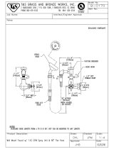
INSTALLATION DIAGRAM
Ball Valves
Optional Water Bypass
Ground Jumper Wire
Ball Valve
Galvanized / Brass Pipe
Optional Whole House
Water Softener
Well Water Pressure Tank
Well Water Source
City Water Source
PRO-WELL System
Optional
Sub-Micron
Post Filter
Drian Line
Optional
UV Filter
Galvanized /
Brass Pipe
To Home

- 6 -
IMPORTANT!
Locate and test the main water supply valve to the home before installing the system. If the main water
supply valve fails to shut o the water completely during the test, we recommend contacting a licensed
plumber to fix the valve before starting the installation.
WARNING!
If the system is installed on a metal (Conductive) plumbing system, i.e.. copper or galvanized metal, the
plastic components of the system will interrupt the continuity of the plumbing system. As a result, any
arrant electricity from improperly grounded appliances downstream or potential galvanic activity in the
plumbing system can no longer ground through contiguous metal plumbing. Some homes may have
been built in accordance with building codes, which actually encouraged the grounding of electrical
appliances through plumbing. A grounded “jumper wire” bridging the equipment and reestablishing the
contiguous conductive nature of the plumbing system must be installed prior to your system use (pg. 5).
WARNING!
Electric Hot Water Tanks: Turn o the power to the unit first to avoid damage.
Well Water: Power o the well water pump and then shut o the main water supply valve.
VALVE SETUP
!
Shut O Main Water Supply
1. Locate the main water supply valve to the house and completely turn o by turning the handle
clockwise.
2. Test to see if the water is completely shut o by turning on the cold water on the closest faucet. If the
cold water cannot be shut o, please contact your local plumber to fix the valve before installing the
system.
1
1. Apply Teflon to the 1” Fittings (included)
and install to the Bypass Valve using an
adjustable wrench.
Recommended Bypass Valve Assembly & Installation
2

- 7 -
1. Remove the tank from carton
2. Lubricate both O-rings on the bottom of the control valve (center and outer).
Valve Preparation
3
VALVE SETUP CONT.
2. Lubricate the o-rings on the
Adapter Couplings to avoid
any leaks.
3. Attache the bypass valve onto
the control head by pressing it
onto the Adapter Couplings.
4. Secure the Bypass to the valve
using the Screws and Metal
Clips.

- 8 -
3. Lubricate the riser tube located on the opening of the tank.
SYSTEM INSTALLATION
4. Install the upper basket on the bottom of the valve by lining up the
tabs, pressing in, then turning the basket counterclockwise to lock it in
place.
5. Place the upper basket over the distributor tube and push the
valve down to the tank and thread the valve on the tank by turning
it clockwise. Be sure not to cross-thread the valve on the tank.
The valve should thread easily in the tank. If not, it may be cross-
threaded.
6. Hand-tighten the valve then snug it further by lightly tapping it with
the palm of your hand. DO NOT over-tighten or use tools to tighten
the valve or damage could occur.

- 9 -
IMPORTANT!
On copper plumbing systems be sure to install a grounding wire between the inlet and outlet piping to
maintain grounding (see diagram on pg. 5).
WARNING!
DO NOT SOLDER WHILE SYSTEM IS CONNECTED. Any solder joints being soldered near the valve must
be done before connecting any piping to the valve. Failure to do this could cause unrepairable damage
to the valve.
1. Apply Teflon tape onto the inlet and outlet fittings.
2. Connect the inlet and outlet of the system using included 18” Flex Lines.
3. Connect the “IN” Flex Line to your incoming water line. Connect the “OUT” Flex Line
to your “IN” line for your home. All piping should be secured to prevent stress on the
bypass valve and connectors.
SYSTEM INSTALLATION CONT.
Connecting the System
4
This system includes 1” male & female NPT connection options. Determine the best options for your
installation. It is recommended that these connections be made using Teflon tape, plumbers putty can be
used to prevent leaks. The inlet and outlet can be identified on the bypass valve by looking at the arrow
directions on top of the bypass valve. The arrow pointing toward the valve is the inlet and the arrow
pointing away from the valve is the outlet.
!

- 10 -
Bypass Position Service Position
IMPORTANT!
The system is not ready for service until you complete the System Startup section of this owner’s manual
SYSTEM INSTALLATION CONT.
5. Place the unit in the Bypass Position.
6. Slowly turn on the main water supply to the system.
7. Locate and the nearest faucet to the system and remove the faucet screen or any fittings on the faucet spout.
8. Turn on the cold water for 10 minutes to flush air and foreign material resulting from the plumbing work.
9. Make sure there are no leaks in the plumbing system before proceeding. Close the water tap when water runs
clear.
!
4. Locate the included drain hose. Using a
sharpies, mark 1/2” from the end of the drain
hose. Connect the marked end of the drain
hose into the Quick Connect drain port on the
valve until it reaches or passes the 1/2” mark
(Remove Locking Clip before pushing hose
in). Run the drain hose to the nearest laundry
tub or drain. This can be ran up overhead or
down along the floor. Drain hose should be a
minimum of 1/2”. If running the drain line more
than 20 ft linear, it is recommended to increase
the hose size to 3/4” and be sure there are
no sags in the hose all the way to the drain
destination.
NOTE:
A direct connection into a waste drain is not recommended. A physical air gap of at least 1.5”
Should be used to avoid bacteria and wastewater traveling back through the drain line into the
system.
?

- 11 -
1. Time of Day
2. Status
3. Time Remaining
4. Backwash Mode
Timer
Setting Button
1. Enter into setting menu
2. Confirm the current setting, and enter into the next step
3. When used simultaneously with up button, it will enter into master programming
Up / Down Buttons
1. Adjust current settings
2. Go one step forward or backward
Cycle Button
1. Save the setting and return to service
2. Enter into queued Backwash mode
3. A long press for 5 - 6 seconds will initiate a immediate regenerate
4. Terminate the current Backwash step and goes to the next step
1. Plug the power transformer into an approved power source. Connect the power cord to the valve. When power
is supplied to the control, the screen will display the time of day, time remaining and the mode.
2. Press and hold the “Cycle” button for 5-6 seconds. The valve will display “GOTO BW” and will continue to move
until it reaches the backwash cycle.
3. Once the valve is in the backwash (BW) cycle the display will show a time value (15). Slowly open the Bypass
Valve to “Service” position to allow water to enter the unit. Air from the tank will begin to push out of the
control valve drain. Allow all air to escape from the unit before turning the bypass fully open. If there is a large
“knocking” sound, the water is being fed too quickly and should be slowed. Once there is a steady stream of
water coming from the system drain with no air coming out, allow water to run until the cycle completes.
1
2
3
4
System Startup
5
VALVE PROGRAMING
The back-light on the screen will go o
automatically after one minute if no buttons
are pressed. To light it up again press any
button on the touch pad.

- 12 -
4. When the backwash cycle is complete, the valve will advance to the brine draw (BD) position then to the (RR)
position. The display will show the (Rapid Rinse) cycle, allow the water to run for the entire rinse cycle
5. When the Rinse Cycle is complete, the valve will advance to the “BF” then the “SR” position.
6. When the cycles complete, the valve will automatically advance to the SERVICE position. Open the nearest
treated water spigot or faucet (remove faucet screen to prevent clogging) and allow the water to run until clear,
close the tap and replace the faucet screen.
1. Setting Time of Day
Default setting 12:00 (24 hours)
Press Settings button and UP
button simultaneously to enter
into Programing Mode
Set the hour
Set the minutes
Press Simultaneously
Press the SETTINGS Button to
accept and continue.
Press UP or DOWN buttons to
change hours.
Press the CYCLE button to
accept and complete the setup.
Press the SETTINGS button
to accept and continue to
Advance Settings.
- Or -
Press UP or DOWN buttons to
change minutes.
VALVE PROGRAMING CONT.
Programing Unit
6
Flashing
Flashing
Flashing

- 13 -
ADVANCE SETTINGS:
The following settings have been pre-set from the factory and are only meant for special
application that requires customized settings.
Continue only if you require customization of the following settings.
?
CONGRATULATION!
Your system is ready for use. Please document the system installation date and maintain the
system at its recommended interval.

- 14 -
1. Setting the Valve Mode
Default setting is "Timer"
Press Up or Down
buttons to change
mode
Press the Settings
Button to accept
and continue.
Set To Timer Mode (T)
Timer (Default Setting)
This mode counts down.
Meter (Not Used)
(Regenerate Immediately)
This setting is not used.
Meter Delay (Not Used)
(Regenerate at 2 am night
of reaching capacity.) This
setting is not used.
NOTE:
Meter and Meter Delay options are not used, there
is no need to set them.
Use the step below to set the Valve to Timer
mode.
ADVANCED SETTINGS
Flashing
Flashing
Flashing
Flashing

- 15 -
Default: 2:00 AM every 072 hours.
Hours Override Range: 3, 4, 6, 8, 12 hours, then every 24 hours (24, 48, 76,…)
2. Backwash Time and Hours Override (Change only if needed)
Timer Mode
ADVANCE SETTINGS CONT.
Press SET to go to Hours
Use UP and DOWN buttons to
adjust the Start Time
Use UP and DOWN buttons to
adjust Hours
Flashing
Flashing
Flashing
Flashing
Flashing

- 16 -
Press the Settings button to
accept and continue to next digit
Press UP or DOWN buttons to
change Back Wash time (Minutes)
Range: 0 - 999
3. Setting the Back Wash Time
Set the Time
Default setting is 015
ADVANCE SETTINGS CONT.
Flashing
Flashing
Flashing
Flashing
Press the Settings button to
accept and continue.

- 17 -
Press the UP button
to change to SET-7
4. Setting the Brine Time (SKIP - This setting us not used)
ADVANCE SETTINGS CONT.
Press the Settings button to
accept and continue.
Flashing
Flashing
5. Setting the Rapid Rinse Time
Press the Settings button to
accept and continue to next digit
Press UP or DOWN buttons to
change the Rapid Rinse time
Range: 0 - 999
Default setting is 010 Minutes
Flashing
Flashing
Flashing
Press the CYCLE button to
accept and complete the setup.

- 18 -
FEATURE & DISPLAYS
3. Manual Queued Backwash
1. Memory During Power Failure
2. Restore Factory Settings
All program settings are stored in permanent memory. Current valve position, cycle step elapsed, time of day are
stored during the power failure. Reset the current time is necessity when power up.
If the valve stopped at a backwash stage when power failure, the valve will return to prior position when it powers
up. It takes 4 to 5 minutes to reset to the position.
The display shows as:
The system will show this status after a
power failure when finding the position.
1) Pull out the power
2) Press the button and plug in the power simultaneously
3) Release the button
The system is now restored
Flashing
The display shows the Queued
Backwash
When the valve is in service position press the button to
activate the queued backwash. The Faucet Icon will blink.
Queued Backwash means the system will initiate a backwash
at the time set. If missed, it will initiate on the next day.
Press the button once again to Cancel the queued
Backwash. The Faucet Icon will blink.
/