Page is loading ...

ACT 5e prox
Operating and Installation
Instructions
ACT Product Code: ACT 5e prox
standalone
ACT 5e prox 2R.indd 1 19/02/2016 17:05:06

ACTstandalone
1
Robust and Reliable.
ACT 5e prox 2R.indd 2 19/02/2016 17:05:08

Copyright © 2016 Access Control Technology Ltd. Part No.18-00094 Issue 1.1
2
ACT 5e prox Operating and Installation Manual
Installation Notes
• Remember to Factory Default the ACT 5e prox before programming.
• Remember to place the supplied varistors across the terminals of the door strike coil
to protect the relay contacts.
• Don’t mount the ACT 5e prox unit near RF sources (e.g. mobile phones, radio
transmitters, etc) or metal surfaces.
• Never use the on-board relays to switch AC mains voltage. An external relay,
electrically isolated from the ACT 5e prox, should be used for this purpose.
• Remember to change the programming code.
• When ordering new cards or fobs specify ACTRFID. (Note: ACT 5e prox will NOT work
with HID cards or fobs.)
Important
As with any Access Control system, always ensure there is an alternate means of escape
in the event of the unit failing to operate due to power loss or in the event of re.
Product Specication
Number of Users 50 (50 PINs and 50 Cards)
Number of Relays 2
Supply Voltage 12 - 24V AC or DC
Current Consumption 60mA (nominal), 130mA (maximum)
Operating Temperature -10 to +50 degrees C
Door Open Time 0 -255 seconds
Relay Contact Rating 5A / 50Vac
Keypad Size Flush Mount: 100 x 110 x 20mm
Surface Mount: 128 x 94 x 18.5mm
Keypad Weight 220 grams
Water Resistance High IP67
Construction Rugged Polycarbonate housing with stainless
steel keys and potted electronics.
Ordering Information
Product Product Code
Proximity card ACTProx ISO-B
Proximity fob ACTProx Fob-B
Proximity half shell card ACTProx HS-B
Proximity card with magnetic stripe ACTProx DUO-B
ACT 5e prox 2R.indd 3 19/02/2016 17:05:08

Copyright © 2016 Access Control Technology Ltd. Part No.18-00094 Issue 1.1
3
ACT 5e prox Operating and Installation Manual
30 Second Programming Guide
1. Enter Programming Mode.
On the digital keypad press button 6. Input the programming code (default is
9999). The LED will ash amber.
2. Change User 1 Code
On the digital keypad press button 0. Input 01 (for User 01). Input the new User
1 code (4 digits).
3. Add User 1 Card
On the digital keypad press button 5. Input 01 (for User 01). Present User 1’s
card twice.
4. Change Programming Code
On the digital keypad press button 0. Input 4. Input the new programming code
(4 digits).
5. Exit Programming Mode
On the digital keypad press button 6. The LED turns red and programming
mode has been exited.
6. Record User Code and Card
Enter the details of the Users and their associated codes and card numbers on
the User List provided in this manual.
The ACT 5e prox is now ready for normal use.
Note: The ACT 5e prox may be returned to its factory default condition at any time by
entering the programming mode and pressing button 4 three times.
ACT 5e prox 2R.indd 4 19/02/2016 17:05:08

Copyright © 2016 Access Control Technology Ltd. Part No.18-00094 Issue 1.1
4
ACT 5e prox Operating and Installation Manual
Programming Summary
Code Function Default
0 Change PIN code 1234 – User 1, 9999 - Programming Code
1 Relay Combinations Timed Relay 1
2 Set Door Relay Time 5 seconds
5 Add User Card
6 Delete User’s Card
7 Delete Card Number
30 Card or PIN On
31 Card or PIN Off
32 Card and any PIN Off
40 Permanent Backlight On
41 Auto Backlighting Off
80 Check User PIN
81 Check User Card
ACT 5e prox 2R.indd 5 19/02/2016 17:05:08

Copyright © 2016 Access Control Technology Ltd. Part No.18-00094 Issue 1.1
5
ACT 5e prox Operating and Installation Manual
ACT 5e prox Programming
On the digital keypad press the button 6 and input the programming code
(initially 9999).
The LED will ash amber while in programming mode. To exit the programming mode
either press button 6 or do not activate any key for 30 seconds.
• If the LED ashes green during programming, then a card presentation is expected.
• If the LED ashes red, then a keypress is expected.
• While the ACT 5e prox is busy performing a task, (e.g. Defaulting memory, adding
cards), the green led will turn on and the buzzer will sound an elongated tone.
Changing User PIN Codes: Enter Programming Mode (69999), then press:
*Remember to update the user list document at the back of this manual after adding a PIN
or Card
Adding Cards: Enter Programming Mode (69999), then press:
Cards may only be assigned to users that do NOT have a card already assigned. When
adding cards to the ACT 5e prox, check which users already have cards by using option
81 (see page 7).
Step Keypad Entry Operation
Example:
Assign code 7529 to
user 7
1 0 Change PIN codes 0 Change PIN codes
2 00-49 Enter 2 digit User Number 00-49 07 User 7
3 0000-9999 4 digit code – 0000 deletes User code 7529 PIN code
Step Keypad Entry Operation
1 5 Add Card
2 00-49 First user to be assigned card
3 Present Card First Card (lowest number card) assigned to rst user
4 Present Card Last Card (highest number card) assigned to last user
Example: Assign card 0000200036 to
user 21:
Keypad Entry Operation
69999 Enter programming
5 Add Card
21 User 21
Present card Card number 0000200036
Present card Card number 0000200036
6
Exit programming
Example: Assign card 0000200036 to
user 21 using the keypad:
Keypad Entry Operation
69999 Enter programming
5 Add Card
21 User 21
0000200036 Enter 10 digit card number
0000200036 Enter 10 digit card number
6
Exit programming
ACT 5e prox 2R.indd 6 19/02/2016 17:05:08

Copyright © 2016 Access Control Technology Ltd. Part No.18-00094 Issue 1.1
6
ACT 5e prox Operating and Installation Manual
Step Keypad Entry Operation
1 0 Change Programming code (Default 9999)
2 Press
4
3 0000-9999 New 4 digit programming code
Step Keypad Entry Operation
1 2 Set Door Relay Time – (default 5 seconds, maximum 255 seconds)
2 0 or 1 0 = Relay 1
1 = Relay 2
Buzzer sounds indicating timing… wait required period
3 Press
4 End setting Door Relay Timer
Step Keypad Entry Operation
1 7 Delete card number
2 10 digit card
number
10-digit Card number with leading zeroes.
E.g. Card 54321, enter 0000054321
Change Programming Code: Enter Programming Mode (69999), then press:
Set Door Relay Times: Enter Programming Mode (69999), then press:
Deleting Card Number: Enter Programming Mode (69999), then press:
Set Relay Combinations: Enter Programming Mode (69999), then press:
Deleting User’s Card: Enter Programming Mode (69999), then press:
Step Keypad Entry Operation
Example:
Set user 12 to activate
relay 2 when access granted
1 1 Set Relay Combinations 1 Set Relay Combinations
2 00-49 Enter 2 digit User Number 00-49 12 User 12
3 0 - 3 0 = Relay 1 Toggle
1 = Relay 1 Timed
2 = Relay 2 Timed
3 = Relay 1 and 2 Timed
2 Relay 2 Timed
Step Keypad Entry Operation
Example:
Delete User 10’s card
1 6 Delete User’s Card 6 Delete cards
2 00-49 First user to delete 10 User 10
3 00-49 Last user to delete 10 User 10
ACT 5e prox 2R.indd 7 19/02/2016 17:05:08

Copyright © 2016 Access Control Technology Ltd. Part No.18-00094 Issue 1.1
7
ACT 5e prox Operating and Installation Manual
Step Keypad Entry Operation
1 80 Check if user has no PIN already assigned
2 00-49 User 0-49
Keypad will ash the green led and sound high-pitched tone if the user has NO
PIN code assigned. It will ash red and sound low-pitched tone, if the user has a
PIN code.
Step Keypad Entry Operation
1 81 Check for user with no card assigned
2 00-49 User 0-49
Keypad will ash the green led and sound high-pitched tone if the user has NO
card assigned. It will ash red and sound low-pitched tone, if the user has a card.
Step Keypad Entry Operation
1 30, 31,32,40 or 41 2 digit option number
2 0 or 1 0=Off, 1=On
Check if User has no PIN Assigned: Enter Programming Mode (69999), then press:
Check if User has no Card Assigned: Enter Programming Mode (69999), then press:
Programming ACT 5e prox Options: Enter Programming Mode (69999), then press:
Option Function Default Operation
30 Card or PIN On When set, a valid Card or valid PIN will open the door.
31 Card and PIN Off When set, only users with both a Card and PIN are
admitted. Cards are assigned to a particular user using the
Adding Cards function (function 5) and PINs are assigned
using the Changing PIN Codes function (function 0).
32 Card and any PIN Off In this mode, a valid card and any valid PIN code will open
the door. This mode allows all users to have a common PIN
code to use with their cards.
40 Permanent Backlight On When set, the keypad illumination is always on. This option
will override option 41 (Auto Backlighting).
41 Auto Backlighting Off When set, the keypad illumination is normally off, but will
switch on in response to any key being pressed, or when
a card is presented or while in programming mode. This
option is overridden by option 40 (Permanent Backlight).
To prevent any illumination, turn off options 40 and 41.
ACT 5e prox 2R.indd 8 19/02/2016 17:05:08

Copyright © 2016 Access Control Technology Ltd. Part No.18-00094 Issue 1.1
8
ACT 5e prox Operating and Installation Manual
Restoring Factory Defaults
Enter Programming Code followed by 444. This restores the ACT 5e prox to its default
settings.
If the Programming Code has been forgotten, it may be set to 9999 by:
1. Remove the power from the unit.
2. Remove link LK1 at the back of the unit.
3. Apply power to unit.
4. Replace link LK1.
5. Programming Code is now set to 9999.
Note: The keypad will not operate correctly without LK1 in place.
Defaulting memory takes 3-4 seconds. During this time, the buzzer will sound an
elongated tone.
ACT 5e prox 2R.indd 9 19/02/2016 17:05:08

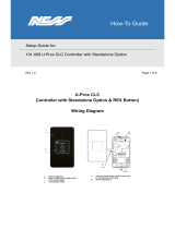
LK 1
PB
N/C
C
N/O
RELAY 1
RELAY 2
IMPORTANT:
Place varistor across all lock terminals
PUSH TO EXIT
PUSH TO EXIT
0V 0V
Power up without link
if programming code
has been lost
Note: The ACT 5e prox
may be powered up from
12V or 24V AC or DC
12V
0V
12V12V
Strike Lock 2Strike Lock 1
Normally
Open
Normally
Open
Copyright © 2016 Access Control Technology Ltd. Part No.18-00094 Issue 1.1
9
ACT 5e prox Operating and Installation Manual
Figure 1: ACT 5e prox 2R Wiring Diagram for Strike Lock
ACT 5e prox 2R.indd 10 19/02/2016 17:05:18

LK 1
PB
N/C
C
N/O
RELAY 1
RELAY 2
IMPORTANT:
Place varistor across all lock terminals
PUSH TO EXIT
PUSH TO EXIT
Magnetic Lock 1
0V 0V
Power up without link
if programming code
has been lost
Note: The ACT 5e prox
may be powered up from
12V or 24V AC or DC
Magnetic Lock 2
12V
0V
12V12V
Copyright © 2016 Access Control Technology Ltd. Part No.18-00094 Issue 1.1
ACT 5e prox Operating and Installation Manual
10
Figure 2: ACT 5e prox Wiring Diagram for Magnetic Lock
ACT 5e prox 2R.indd 11 19/02/2016 17:05:28

Copyright © 2016 Access Control Technology Ltd. Part No.18-00094 Issue 1.1
11
ACT 5e prox Operating and Installation Manual
Figure 3 – Mounting instructions for surface mount unit
Surface Mount Unit
Place the reader / keypad onto the surface
mount collar and clip down into place. Use
the security screw supplied to attach the unit
to the surface mount collar.
The surface mount collar is mounted on the
wall using the fixing kit supplied in the box.
Security screw
supplied with the unit
Place the cap onto the unit
and push firmly in place
ACT 5e prox 2R.indd 12 19/02/2016 17:05:29

Flush Mount Unit
Mounting plate is attached to the pattress
using the
screws supplied.
Ensure the correct spacers have
been used to bridge the gap between the mounting
plate and the fixing wings of the pattress
box to avoid
the mounting plate being distorted.
Place the reader / keypad onto the
surface mount collar and clip
down into place. Use the security
screw supplied to attach the unit
to the flush mount collar.
Security screw
supplied with the unit
Screws
Standard
pattress box
Place the cap onto the unit
and push firmly in place
Note:
Determine the distance between the pattress box
and the mounting plate, using the spacers that are
labelled 1mm to 4mm. A spacer of the correct
length is assembled by stacking the spacers
together.
Spacers break away
from main component
when required by
installer for use
View showing spacer
stacking
View shows mounting
plate before spacers are
broken away by installer
Copyright © 2016 Access Control Technology Ltd. Part No.18-00094 Issue 1.1
ACT 5e prox Operating and Installation Manual
12
Figure 4– Mounting instructions for ush mount unit
ACT 5e prox 2R.indd 13 19/02/2016 17:05:29

13
User User Name Card Number Pin Relay
00
01
02
03
04
05
06
07
08
09
10
11
12
13
14
15
16
17
18
19
20
21
22
23
24
25
26
27
28
29
30
31
32
33
34
35
36
37
38
39
40
41
42
43
44
45
46
47
48
49
12
John Smith 000200036 7529 1
Example:
ACT 5e prox 2R.indd 14 19/02/2016 17:05:30

14
Location
Date of Installation
Device Wire Colour
Power
Relay 1
Relay 2
Push Button 1
Push Button 2
Break Glass 1
Break Glass 2
Use the tables below to
record your wiring and
make your next visit easier.
ACT 5e prox 2R.indd 15 19/02/2016 17:05:30

Ireland Ofce
Unit C1, South City Business Centre,
Tallaght, Dublin 24, Ireland
United Kingdom Ofce
Birchwood 1, Dewhurst Road, Birchwood
Warrington, WA3 7GB, UK
Ireland: +353 (0)1 466 2570
UK: +44 (0)161 236 9488
Email: [email protected]
www.act.eu
Copyright © 2016 Access Control Technology Ltd. Part No. 18-00094 Issue 1.1
Access Control Technology Ltd. reserve
the right to change the contents of this
manual and the system it applies to
without prior notice.
While every effort has been taken by ACT
to ensure the accuracy of the information
contained within this document, ACT
assumes no responsibility for any errors
or omissions. No liability is assumed
for damages resulting from the use
of information contained within this
document.
ACTing for the installer
for over 20 years
Established
1995
ACT 5e prox 2R.indd 16 19/02/2016 17:05:30
/