49-80816-1 5
Controls
USING THE HOOD: Controls / Chef Connect
Chef Connect Operation Bluetooth
®
Connection
To pair with another device:
To start the pairing process on the hood, press and hold
the Chef Connect button for 3 seconds. The backlight
for all the icons will light up until the hood is paired with
the range or other device. If the pairing is successful,
the backlights of all five buttons will flash simultaneously
three times and then turn off and the backlight for the
Chef Connect button will turn on.
It will time out after 2 minutes if the pairing is not
completed, after which the pairing sequence will need to
be restarted.
To cancel pairing:
To cancel the pairing, hold the Chef Connect button
down for 3 seconds and then turn off the hood.
Default Sync Settings:
The factory default setting for the light will be the brightest.
The factory default setting for the fan sync will be OFF.
The user can change the Default Sync Settings by
pressing and holding the Low button for 3 seconds.
This will enter the Default Settings Mode. Once in this
mode, the backlights for all buttons will blink on/off
indefinitely and the fan and light will switch to the current
Default Sync Setting, so the user knows what the current
default value is. At this time, set the light and fan to the
desired default levels. Once the user is satisfied with the
selection, press and hold the Off button for 3 seconds.
This will exit this mode. At that time the backlights
will stop blinking and the state of the fan and light will
change back to their prior state before entering the
Default Settings Mode.
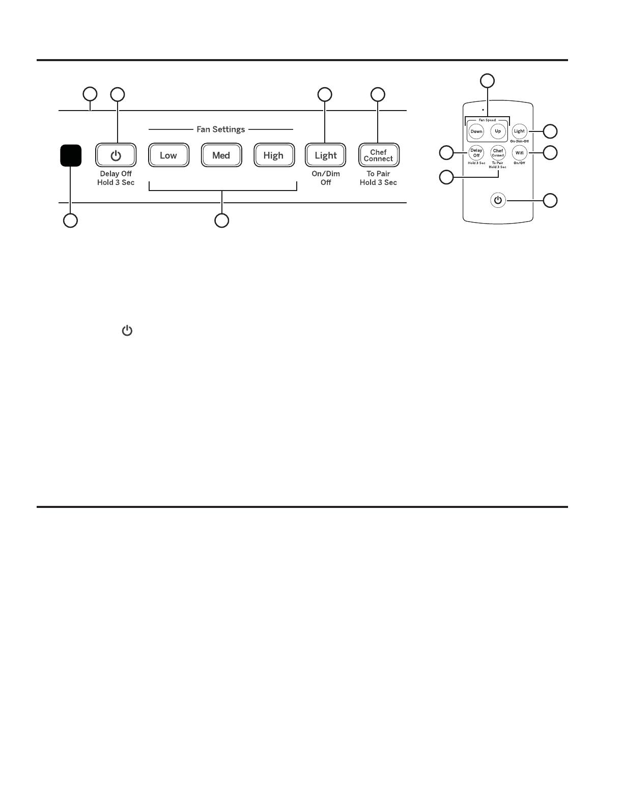
Chef Connect
1. Rangehood Control Panel: The control panel
is located on the front of the canopy. The position
and function of each control button are noted below.
2. Fan On/Off: On/Off switch for the fan. The fan
can be operated by pressing any of the fan setting
buttons. Hold for 3 seconds to activate Delay Off
feature, which automatically turns the fan off after
15 minutes.
3. Fan Settings: Speed control for fan. Press the
button Low for LOW speed, Med for MEDIUM
speed, and High for HIGH speed. On Remote,
press Up to increase fan speed, press Down to
decrease fan speed, including Boost.
4. Light: On/Dim/Off switch for the LED lights. Press
the Light button to turn the lights on, again to set the
lights to dim setting, and again to turn the lights off.
5. Chef Connect: This is a Bluetooth
®
pairing feature
for use with other compatible Chef Connect enabled
products on a cooktop or range. When the device is
paired, the light and fan will turn ON at the Default
Sync Settings upon receiving a command from the
range or cooktop. It will remain ON at that setting until
the user changes it. To pair devices, hold down the
Chef Connect button for 3 seconds. To turn it back
off, hold the button down for another 3 seconds. See
the Chef Connect section for more details.
6. IR Sensor: Remote control receiver when used
with remote control kit (UXRC1).
7. Wi-Fi (Remote only): Not available.
8. Delay Off (Remote only): Press and hold
Delay Off to toggle Delay Off function.
36
1
245
3
4
78
5
2
Remote Control


