S R Smith 400-7001 Owner's manual

Category
Rechargeable batteries
Type
Owner's manual

S R Smith 400-7001 is a versatile battery-powered pool lift control system designed to operate S.R. Smith lift products and many other actuated lift control systems. It features a user-friendly touchpad control for convenient operation, an emergency stop button for safety, and a rechargeable battery pack for cordless operation. The optional activation key provides enhanced security by requiring a key to operate the control, ensuring unauthorized usage is prevented. Furthermore, the USB port allows you to download the lift's performance log for maintenance and troubleshooting purposes.

S R Smith 400-7001 is a versatile battery-powered pool lift control system designed to operate S.R. Smith lift products and many other actuated lift control systems. It features a user-friendly touchpad control for convenient operation, an emergency stop button for safety, and a rechargeable battery pack for cordless operation. The optional activation key provides enhanced security by requiring a key to operate the control, ensuring unauthorized usage is prevented. Furthermore, the USB port allows you to download the lift's performance log for maintenance and troubleshooting purposes.

700-0500 Rev 4.3.2015
1
LiftOperator™ Owner’s Manual and
Maintenance Procedures
1017 SW Berg Parkway
Canby, OR 97013
Phone: 503.266.2231
Toll Free: 800.824.4387
www.srsmith.com
700-0500 Rev 4.3.2015
2
TABLE OF CONTENTS
INTRODUCTION 3
PRODUCT OVERVIEW 4
COMPONENT DESCRIPTION / OPERATION 4
BATTERY PACK 6
INSTALLING CONTROL UNIT AND BATTERY PACK 8
CONTROL MAINTENANCE 9
TROUBLE SHOOTING 9
LONG TERM STORAGE 10
WARRANTY INFORMATION 10
SPECIFICATIONS 11
PARTS LIST 11
700-0500 Rev 4.3.2015
3
INTRODUCTION
The purpose of this document is to provide information relating to the safe operation, care, and
maintenance of the LiftOperator Control and Rechargeable Battery pack.
INTENDED LIFT USER
All of S.R. Smith’s lifts have been designed to assist individuals requiring assistance entering or exiting a
swimming pool or spa - however, the User should not exceed the weight limit of the product (300 lb/136
kg to 400 lb/181 kg depending upon model). It is the responsibility of the lift Owner to ensure that safety
procedures are put in place and a risk assessment is completed. Mental or physical disabilities may
require assisted transfer, and the Owner is responsible for determining the number of qualified attendants
to complete the poolside transfer and the number of persons required to be in the water, ready to receive
and assist the User. The correct stabilizing system (seat belt or stability vest) must be attached to the seat
and fully fastened and used during each transfer.
Our goal is to provide our customers with the most advanced and innovative designs offering exceptional
quality at affordable prices. All of our lifts meet the specifications set forth by the Access Board - ADAAG
2004 (US only), Medical Device Directive, 93/42/EEC, RoHS2 Directive 2011/65/EU, EN 50581:2012
and ISO10535:2006 including repeating the lifting cycle of the hoist (lift) for a total of 11,000 cycles. The
lift system and AC powered battery charger complies with EN60601-1-2, 2007/03.
USING THE LIFTOPERATOR CONTROL
Obey all User Instructions listed in the Owner’s Manual whenever using lift. Obey all Caution,
Warning, Operating Instruction(s) and Labels located on the lift whenever using. It is the
responsibility of the lift Owner to ensure that safety procedures are put in place and a risk assessment is
completed. Mental or physical disabilities may require assisted transfer, and the Owner is responsible for
determining the number of qualified attendants to complete the poolside transfer and the number of
persons required to be in the water, ready to receive and assist the User. If the lift will be used by a
disabled person living on their own, a communication device should be installed in the area of use
to call for assistance in the event of an emergency. Only persons healthy enough for water
activities should use the lift. Users should consult with their physician to determine if water
activities are appropriate for the User. Keep fingers and hands clear of lift arms during use.
WARNING: A SEATBELT OR STABILITY VEST MUST BE ATTACHED TO THE SEAT
AND FULLY FASTENED AND USED DURING EACH TRANSFER.
US Patent Pending
LiftOperator and the LiftOperator logo are registered trademarks of S.R. Smith, LLC.
700-0500 Rev 4.3.2015
4
PRODUCT OVERVIEW
The LiftOperator – Pool Lift Control System with Rechargeable Battery Pack is designed to operate any
S.R. Smith lift product as well as many other actuated lift control systems. It can be used with the
applicable 2 or 4 button hand held controls. It features a secondary control touch pad on the faceplate to
recall the seat to the deck when the seat and hand control are in the water, or in the event the primary
hand control fails. It also incorporates an emergency stop button that activates an audible alert. The
touchpad has LED indicators that indicate “Battery (Energy) Level”, “Emergency Alert” activation and
“Service Required” when maintenance” is required based on lift usage. The lift performance information -
i.e. up/down, left/right, battery charge cycles and to reset the “Service Required” LED are
viewed/completed via the USB port on the bottom of the control via a standard FAT-formatted USB mass
storage device (not included). The lift performance log information can be downloaded to a PC for viewing
and record keeping. The unit can be ordered with an optional activation key system that is used to turn
the control On/Off. This is intended to be used in locations where having an “always-on” unit is not
practical due to safety issues or lack of an attendant. The unit is constructed of high impact, UV resistant
plastic, is water resistant and available in 2 and 4 button configurations. The removable battery pack is
rechargeable via the included transformer. The included lock plate for the battery pack prevents
unauthorized removal of the battery pack with the use of padlock (not included). All circuit boards have
been conformal coated to add an extra layer of protection against moisture and corrosion.
Application
For use with any S.R. Smith lift product as the standard lift control. It can be used as a replacement unit
for any existing S.R. Smith lift or many other common actuated lifts. The unit mounts to existing mounting
holes.
COMPONENT DESCRIPTION / OPERATION
Control Box
The LiftOperator is available in two models - a 2 button Control and a 4 button Control. Both are available
with an optional Activation Key feature that provides a higher level of security by allowing control
operation only with the use of the activation key. The unit controls all lift operations identical to the user
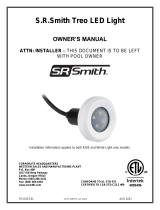
hand set. Two or three cables connect to the bottom of the Control Box to enable operation of the lift. The
largest connector is for the hand control. Connector # 1 is for the motor cable (red stripe). Connector # 2
is for the actuator cable (green stripe - 4 button Control only).
Touchpad Control –
The touchpad control arrow keys can be used in the
event that the hand control is out of reach or fails. Simply
press and hold the arrow for the desired action for one
movement at a time – Up, Down, Left, Right Releasing
the Arrow stops movement.
Battery Level LED Indicators –
The Battery Level LED Indicators show battery charge
levels. The LED’s will illuminate when either the touchpad
control or the hand control is activated and will stay lit for
10 seconds. At greater than 50% the LED glows Green,
at less than 50% the LED glows Amber, and less than
25% the LED glows red and indicates the battery requires
charging. If the less than 25% LED glows red, do not
operate the lift. Remove the battery and fully charge
before use.
CONNECTOR 1
(MOTOR CABLE)
CONNECTOR 2
(ACTUATOR CABLE)
700-0500 Rev 4.3.2015
5
Service Required LED –
The Service Required LED will illuminate when the battery pack has been removed/replaced 120
times - approximately once every 4 months. This indicates that required maintenance for the lift
must be completed. Please see the maintenance section of the Lift Owner’s Manual for the
requirements. The Service Required LED can be reset by inserting a standard FAT-formatted
USB mass storage device (not included) into the USB Port on the bottom of the controller. When
the service light is illuminated the lift must not be used until required maintenance is
performed.
Emergency Stop Button –
In the event of an emergency, or if you need to stop lift movement
immediately, pressing the Emergency Stop Button (red button on the
control) will stop all lift movement. At the same time an audible alert
will sound for 10 sec. then pause for 5 sec. and then the sequence will
repeat until the button is reset by turning it in the direction of the
arrows on the button (clockwise). The Emergency Alert LED will also
flash Red when the button is pressed and will remain flashing unit the
button is reset.
The Emergency Alert (audible and LED) can be activated by pressing
any two buttons on the hand control at the same time (provided with
the lift). This will stop all lift movement and activate the audible alert
and the Red LED will flash. Once both buttons are released, the lift
will return to normal operation and the emergency audible alert will
silence.
Activation Key –
The Optional Activation Key provides a higher level of security by
allowing control operation only with the use of the optional activation
key. To enable operation slide the Access Key into the slot next to the
touchpad control arrows. To disable operation remove the key. When
the key is inserted or removed the Battery Level LED will illuminate for
10 seconds.
USB Port –
The LiftOperator control contains a USB port that is used to download the performance log of the
lift. Using any standard FAT file formatted USB memory stick (widely available through retail
outlets) insert the stick into the slot on the bottom of the control on the far right hand side. Press
any of the touchpad control arrows; all three of the Battery Level LED’s will flash. During
downloading the Green greater than 50% Battery Level LED will flash. If the unit has a problem
downloading the performance log the Amber less than 25% LED will flash. Remove the USB
from the port and re-insert it. If the Amber 25% LED flashes again, confirm that the USB you are
using is FAT file formatted. The information from the USB can be downloaded to a PC for review
and/or copied to a spread sheet. The performance log will retain approximately 7,600 events.
Once the file is full it will remove the oldest event and replace with the newest.
After the summary data, the events are shown with the oldest first. The first column is the time in
seconds from that last event. The second column is the text describing the event. The third
column is duration of the activity noted in seconds.
4-Button Hand Control
Activation Ke
y (Option)
700-0500 Rev 4.3.2015
6
An example of a short log file:
Activity Description
dev_id_upper,0 Programing data
dev_id_lower,1 Programing data
fw_rev,90 Firmware rev.
batt_volt_float,24929 Non-loaded battery voltage in millivolts
batt_volt_load,21487 Loaded battery voltage in millivolts
batt_capacity,99 Estimated battery capacity in %
charge_starts,8 Number of times charging was attempted
charge_completes,1 Number of times charging was finished successfully
--------
0,power_on,1 Connecting Battery Pack
0,key_enable, Inserting Activation Key
2,alert_pressed, Emergency Button pressed
3,alert_released, Emergency Button released
8,lift_up,2 Lift movement - up
5,lift_down,2 Lift movement - down
11,lift_up,2
4,turn_left,2 Lift movement - turn left
3,turn_right,1 Lift movement - turn right
308,key_disable, Removing Activation Key
3,log_write, USB File Download
BATTERY PACK
The battery pack is located on top of the Control Box and is removable.
700-0500 Rev 4.3.2015
7
To remove - pull the battery pack away from the mounting plate so that the latch on the battery
pack clears the side tabs on the mounting plate - then lift the battery pack up and away from the
Control Box.
To replace - align the battery pack with the mounting plate so that the latch will drop over the
center tab and that the bottom of the battery pack will fit in the recessed area on top of the Control
Box. Lower the battery pack in place so that the latch is fully captured by the mounting plate and
the battery pack drops fully seated onto the Control Box.
The battery pack should be charged daily. Do not allow battery
to fully discharge, as it will shorten battery life. Whenever
battery is removed from Control Box or lift is not in use it is
important to connect battery to the charger. This ensures
battery is fully charged and ready for use.
The battery pack has an LED indicator near the plug-in-port. It
will glow Red when first plugged into the transformer. If the
LED remains Red this indicates the battery pack needs
charging. When fully charged the LED will glow Green. If the
battery is fully charged and is plugged into the transformer the
LED will glow Red for approximately 10 sec. then glow Green.
If the LED flashes Red when plugged in this indicates a fault
with the battery and indicates the battery pack should be
replaced. All batteries are inspected prior to shipment. See
warranty policy regarding battery replacement to to problems
after sale. Batteries have a normal lifespan of between 2-3
years, depending on use and care. A fully charged battery will provide approximately 30 to 40-lifting
cycles, depending on the weight of the users. Prior to use the battery charge level should be checked by
observing the LED indicator above the charger plug to ensure sufficient charge level. The charger must
be connected to the battery to view the LED.
It is not necessary to fully discharge the battery prior to charging. Battery should be charged daily and
cannot be overcharged. It takes up to twelve hours to fully charge depending upon battery usage. Do not
allow battery to fully discharge, as it will shorten battery life. Whenever battery is removed from Control
Box or the lift is not in use it is important to connect battery to charger. This ensures battery is fully
charged and ready for use.
Do not drop the battery, as it could cause the unit to fail. If the battery case is cracked do not use and
replace the battery. Do not place battery on a conductive surface. During temperature extremes beyond
the range of 41 F (5 C) to 104 F (40 C) remove battery and place in a controlled environment or battery
life may be shortened.
Battery Disposal
The batteries located inside the battery pack are recyclable and shall be disposed of in accordance with
applicable local, state/provincial or federal/national regulations.
700-0500 Rev 4.3.2015
8
Locking Plate Assembly
The battery pack can be secured to the mounting plate using the provided lock plate assembly. To install
open the lock plate so that the bottom tabs are moved close to one another to allow the lock plate to be
inserted into the slots on the mounting plate secured to the lift. Close the lock plate assembly so that the
tabs are captured by the slots. Insert a padlock (not provided) through the holes on the lock plate
assembly to secure it.
Console/Battery Cover
Keep the Console/Battery Cover installed at all times to prevent moisture from collecting on the Control
Box and battery. Excessive moisture collection can affect battery and lift performance and could lead to
battery failure and/or the lift failing to operate. Whenever the battery is removed for charging the
Console/Battery Cover must be placed over the Control Box to protect the unit from the elements.
INSTALLING THE CONTROL UNIT AND RECHARGABLE BATTERY PACK
1. Insert motor plug (with red stripe) into connector #1 on Control Box. Make sure plug is fully inserted
and secure (4 Button Control Unit only).
2. Insert actuator cable plug (green stripe) into connector #2 on Control Box. Make sure plug is fully
inserted and secure.
3. Insert hand control plug into large connector on Control Box. Make sure plug is fully inserted and
secure.
4. Attach battery to Control Box. To remove battery pull slightly away from mounting plate and lift
battery pack off of the Control Box.
5. Cover Control Box and battery with Console/Battery Cover to protect from moisture.
6. Check up and down controls for proper operation - both touch pad and hand controls.
7. Check side to side controls for proper operation – both touch pad and hand controls (4 Button
Control only).
8. Check Emergency Stop button for operation/activation of internal sounder.
9. For Controls with the optional Activaiton Key – Key must be inserted into slot for operation. When
Key is removed lift with not operate. (Note – Emergency Stop button and alert will operate without
Key inserted into slot)
To replace an existing control/battery pack with The LiftOperator – Pool Lift Control System with
Rechargeable Battery remove the existing mounting plate and install the provided mounting plate using
the existing screws. Connect cables and test units as indicated above.
700-0500 Rev 4.3.2015
9
In Case of Hand Control Failure
Use the touchpad control on the front of the Control Box. Press the directional arrows for the operation
required and hold the arrow down for movement. Release the arrow when finished.
If the lift will be used by a disabled person living on their own, a communication device should be
installed in the area of use to call for assistance in the event of an emergency or lift failure.
CONTROL MAINTENANCE
Proper maintenance will prolong the life of your control unit.
Keep all electronic components clean and dry
Keep the Console/Battery Cover installed at all times to prevent moisture from collecting on the
Control Box and battery. Excessive moisture collection can affect battery and lift performance and
could lead to battery failure and/or the lift failing to operate.
If the lift is used outdoors, an optional full cover is available and recommended.
Owners of lifts should be aware of any and comply with any applicable local, state/provincial or
federal/national regulations regarding the inspection and or testing of lifts.
TROUBLE SHOOTING
Be sure the battery is fully charged before troubleshooting.
Lift does not rotate
Does lift raise or lower?
Yes.
1. Check connection to Control Box. Be sure plug is pushed in all the way.
2. Check hand control connection to Control Box for damaged pins.
3. Check connections on terminal block located on frame for loose wires.
4. Check connection cable for damage.
5. Reverse the motor cables as follows: Locate the area on the Control Box where the
cables are attached. Remove the motor cable from connector #1 and replace it with the
actuator cable from connector #2. Activate the up and down buttons on the hand control.
If lift rotates, the problem is likely the hand control. If lift does not rotate, the problem is
likely the 24v motor. If this happens contact your Authorized Reseller or S.R. Smith for
replacement information.
Does lift raise or lower?
No.
1. Check battery charge level.
2. Check battery connection.
3. Use another fully charged battery. If lift continues to not function, replace the Control
Box.
Lift does not Raise or Lower
Does lift rotate?
Yes.
1. Check connection to Control Box. Be sure plug is pushed in all the way.
2. Check hand control connection to Control Box for damaged pins.
3. Check connection cable for damage.
700-0500 Rev 4.3.2015
10
4. Use touch pad control. Activate these buttons by pressing down. If lift operates
properly, the problem is likely the hand control. If lift does not operate properly, the
problem is likely the actuator.
Does lift rotate?
No.
1. Check battery charge level.
2. Check battery connection.
3. Use another fully charged battery. If lift does not function, replace the Control Box.
If troubleshooting does not resolve the issue, contact S.R. Smith at 800.824.4387 or 503-266-2231 or
info@srsmith.com.
LONG-TERM STORAGE
When storing the lift for an extended period of time:
Keep the battery on the charger in a dry temperature controlled area.
Questions/Comments - Contact us at 800.824.4387 or 503-266-2231 or info@srsmith.com. For
information regarding Authorized Resellers worldwide visit www.srsmith.com
WARRANTY INFORMATION
The S.R. Smith warranty becomes effective on the date of manufacture.
To initiate a warranty replacement, Please follow the process outlined below.
1. Take photos of the damaged product.
a) The photo must include the entire unit (i.e. board and stand or slide from a distance).
b) Also include one photo or more of the damaged area.
2. Remove the serial # sticker from the product.
a) S.R. Smith provides a serial # for every board, stand, slide and rail product we produce. The
sticker with the serial number for our boards, stands and slides is a silver, 1" long rectangular
sticker found on the side or bottom of the item. The serial # sticker for our rail products is clear
and 2" long. It will be found on the inside of the topmost curve.
3. Attach the photos and the serial # sticker to a written request for replacement under the
S.R. Smith warranty. Please include the following information:
a) Product name and description. (i.e.: board length/color, curve direction of slide, etc.)
b) Date of purchase and/or date of installation.
c) Description of damage.
d) Shipping address with a contact name and phone number.
4. Return to us by mail or email at http://www.srsmith.com/en/customer-
service/warranty-information/ the photos, serial # sticker and your written request to:
S.R. Smith, LLC
PO Box 400
1017 SW Berg Pkwy
Canby, OR 97013
Attn: Warranty Specialist
700-0500 Rev 4.3.2015
11
**Please Note: Missing information will result in a processing delay and possibly denial of your
claim.
Should you have any questions regarding this process, please contact
S.R. Smith's Warranty specialist at 800.824.4387 or 503-266-2231 or email warranty@srsmith.com
SPECIFICATIONS
LiftOperator – 2 Button Control Assembly 1001540, 4 Button Control Assembly 1001499, 2 Button
Control Assembly w/Activation Key 1001545, 4 Button Control w/Activation Key 1001555,
Replacement Rechargeable Battery Pack 1001495
1. Specifications
Dimensions:
Control Unit - 6.76” L (17.17 cm)/ 4.96” W (12.59 cm)/ 4.67” D (11.86 cm)
Battery Pack - 9.95” L (25.27 cm)/ 4.96” W (12.59 cm)/ 4.67” D (11.86 cm)
Overall - 16.71” L (42.44 cm)/ 4.96” W (12.59 cm)/ 4.67” D (11.86 cm)
Weight:
Control Unit – 2.0 lbs. (.91 kg) with mounting plate.
Battery Pack - 9.3 lbs. (4.22 kg)
Total Weight – 11.3 lbs. (5.12 kg) – Shipping Weight – 12.0 lbs. (5.44 kg)
Battery 24V DC, IP 65 Gel Cell Lead Acid
Temperature Range 41 F (5 C) to 104 F (40 C)
Battery Life 30 cycles (approximate per charge)
PARTS LIST
Description
1001540 2 Button Control
1001545 2 Button Control w/Activation Key
1001499 4 Button Control
1001555 4 Button Control w/Activation Key
1001495 Replacement Battery Pack
1001530 Battery Charger
910-1000 Console Cover
  • Page 1 1
  • Page 2 2
  • Page 3 3
  • Page 4 4
  • Page 5 5
  • Page 6 6
  • Page 7 7
  • Page 8 8
  • Page 9 9
  • Page 10 10
  • Page 11 11

S R Smith 400-7001 Owner's manual

Category
Rechargeable batteries
Type
Owner's manual

S R Smith 400-7001 is a versatile battery-powered pool lift control system designed to operate S.R. Smith lift products and many other actuated lift control systems. It features a user-friendly touchpad control for convenient operation, an emergency stop button for safety, and a rechargeable battery pack for cordless operation. The optional activation key provides enhanced security by requiring a key to operate the control, ensuring unauthorized usage is prevented. Furthermore, the USB port allows you to download the lift's performance log for maintenance and troubleshooting purposes.

Ask a question and I''ll find the answer in the document

Finding information in a document is now easier with AI