ASROCK WOLFDALE1333-GLANR2 Datasheet
- Category
- Motherboards
- Type
- Datasheet

11
11
1
Wolfdale1333-GLAN
User Manual
Version 2.0
Published December 2007
Copyright©2007 ASRock INC. All rights reserved.

22
22
2
Copyright Notice:Copyright Notice:
Copyright Notice:Copyright Notice:
Copyright Notice:
No part of this manual may be reproduced, transcribed, transmitted, or translated in
any language, in any form or by any means, except duplication of documentation by
the purchaser for backup purpose, without written consent of ASRock Inc.
Products and corporate names appearing in this manual may or may not be regis-
tered trademarks or copyrights of their respective companies, and are used only for
identification or explanation and to the owners’ benefit, without intent to infringe.
Disclaimer:Disclaimer:
Disclaimer:Disclaimer:
Disclaimer:
Specifications and information contained in this manual are furnished for informa-
tional use only and subject to change without notice, and should not be constructed
as a commitment by ASRock. ASRock assumes no responsibility for any errors or
omissions that may appear in this manual.
With respect to the contents of this manual, ASRock does not provide warranty of
any kind, either expressed or implied, including but not limited to the implied warran-
ties or conditions of merchantability or fitness for a particular purpose.
In no event shall ASRock, its directors, officers, employees, or agents be liable for
any indirect, special, incidental, or consequential damages (including damages for
loss of profits, loss of business, loss of data, interruption of business and the like),
even if ASRock has been advised of the possibility of such damages arising from any
defect or error in the manual or product.
This device complies with Part 15 of the FCC Rules. Operation is subject to the
following two conditions:
(1) this device may not cause harmful interference, and
(2) this device must accept any interference received, including interference that
may cause undesired operation.
CALIFORNIA, USA ONLY
The Lithium battery adopted on this motherboard contains Perchlorate, a toxic
substance controlled in Perchlorate Best Management Practices (BMP) regulations
passed by the California Legislature. When you discard the Lithium battery in
California, USA, please follow the related regulations in advance.
“Perchlorate Material-special handling may apply, see
www.dtsc.ca.gov/hazardouswaste/perchlorate”
ASRock Website: http://www.asrock.com

33
33
3
ContentsContents
ContentsContents
Contents
1 Introduction1 Introduction
1 Introduction1 Introduction
1 Introduction
......................................................................................................
......................................................................................................
...................................................
5 5
5 5
5
1.1 Package Contents.......................................................... 5
1.2 Specifications ................................................................ 6
1.3 Minimum Hardware Requirement Table for Windows
®
Vista
TM
Premium 2007 and Basic Logo ....................... 9
1.4 Motherboard Layout........................................................ 10
1.5 ASRock HD 6CH I/O....................................................... 11
2 Installation2 Installation
2 Installation2 Installation
2 Installation
..........................................................................................................
..........................................................................................................
.....................................................
12 12
12 12
12
2.1 Screw Holes ................................................................. 12
2.2 Pre-installation Precautions........................................... 12
2.3 CPU Installation.............................................................. 13
2.4 Installation of Heatsink and CPU fan ............................. 15
2.5 Installation of Memory Modules (DIMM)......................... 16
2.6 Expansion Slots (PCI and PCI Express Slots) ..................... 17
2.7 Jumpers Setup ............................................................... 18
2.8 Onboard Headers and Connectors .................................. 19
2.9 HDMI_SPDIF Header Connection Guide......................... 23
2.10 SATAII Hard Disk Setup Guide ........................................ 24
2.11 Serial ATA (SATA) / Serial ATAII (SATAII) Hard Disks
Installation...................................................................... 25
2.12 Driver Installation Guide .............................................. 25
2.13 Untied Overclocking Technology .................................... 25
3 BIOS S3 BIOS S
3 BIOS S3 BIOS S
3 BIOS S
ETUP UTILITYETUP UTILITY
ETUP UTILITYETUP UTILITY
ETUP UTILITY
....................................................................................
....................................................................................
..........................................
26 26
26 26
26
3.1 Introduction..................................................................... 26
3.1.1 BIOS Menu Bar..................................................... 26
3.1.2 Navigation Keys .................................................... 27
3.2 Main Screen ................................................................... 27
3.3 Advanced Screen ............................................................ 27
3.3.1 CPU Configuration ................................................ 28
3.3.2 Chipset Configuration ............................................ 30
3.3.3 ACPI Configuration ................................................ 32
3.3.4 IDE Configuration .................................................. 33
3.3.5 PCIPnP Configuration ........................................... 35
3.3.6 Floppy Configuration ............................................. 36
3.3.7 Super IO Configuration .......................................... 36
3.3.8 USB Configuration ................................................ 37
3.4 Hardware Health Event Monitoring Screen...................... 38

44
44
4
3.5 Boot Screen ................................................................... 39
3.5.1 Boot Settings Configuration ................................... 39
3.6 Security Screen.............................................................. 40
3.7 Exit Screen .................................................................... 41
4 Software Support4 Software Support
4 Software Support4 Software Support
4 Software Support
....................................................................................
....................................................................................
..........................................
42 42
42 42
42
4.1 Install Operating System ................................................ 42
4.2 Support CD Information................................................... 42
4.2.1 Running Support CD ............................................. 42
4.2.2 Drivers Menu ......................................................... 42
4.2.3 Utilities Menu ........................................................ 42
4.2.4 Contact Information ............................................... 42

55
55
5
Chapter 1 IntroductionChapter 1 Introduction
Chapter 1 IntroductionChapter 1 Introduction
Chapter 1 Introduction
Thank you for purchasing ASRock Wolfdale1333-GLAN motherboard, a reliable
motherboard produced under ASRock’s consistently stringent quality control. It delivers
excellent performance with robust design conforming to ASRock’s commitment to qual-
ity and endurance.
In this manual, chapter 1 and 2 contain introduction of the motherboard and step-by-
step guide to the hardware installation. Chapter 3 and 4 contain the configuration
guide to BIOS setup and information of the Support CD.
Because the motherboard specifications and the BIOS software might be
updated, the content of this manual will be subject to change without
notice. In case any modifications of this manual occur, the updated
version will be available on ASRock website without further notice. You
may find the latest VGA cards and CPU support lists on ASRock website
as well. ASRock website
http://www.asrock.com
If you require technical support related to this motherboard, please visit
our website for specific information about the model you are using.
www.asrock.com/support/index.asp
1.1 P1.1 P
1.1 P1.1 P
1.1 P
ackack
ackack
ack
age Contentsage Contents
age Contentsage Contents
age Contents
ASRock Wolfdale1333-GLAN Motherboard
(ATX Form Factor: 12.0-in x 7.5-in, 30.5 cm x 19.1 cm)
ASRock Wolfdale1333-GLAN Quick Installation Guide
ASRock Wolfdale1333-GLAN Support CD
One 80-conductor Ultra ATA 66/100 IDE Ribbon Cable
One Ribbon Cable for a 3.5-in Floppy Drive
One Serial ATA (SATA) Data Cable (Optional)
One Serial ATA (SATA) HDD Power Cable (Optional)
One HDMI_SPDIF Cable (Optional)
One “ASRock HD 6CH I/O” I/O Shield

66
66
6
1.21.2
1.21.2
1.2
SpecificationsSpecifications
SpecificationsSpecifications
Specifications
Platform - ATX Form Factor: 12.0-in x 7.5-in, 30.5 cm x 19.1 cm
CPU - LGA 775 for Intel
®
Dual Core Core
TM
2 Extreme / Core
TM
2 Duo
/ Pentium
®
Dual Core / Celeron
®
, supporting Dual Core Wolfdale
processors
- Compatible with all FSB1333/1066/800/533MHz CPUs
except Quad Core (see CAUTION 1)
- Supports Hyper-Threading Technology (see CAUTION 2)
- Supports Untied Overclocking Technology (see CAUTION 3)
- Supports EM64T CPU
Chipset - Northbridge: Intel
®
945GC A2
- Southbridge: Intel
®
ICH7
Memory - Dual Channel DDR2 Memory Technology (see CAUTION 4)
- 2 x DDR2 DIMM slots
- Support DDR2 667/533 (see CAUTION 5)
- Max. capacity: 4GB (see CAUTION 6)
Hybrid Booster - CPU Frequency Stepless Control (see CAUTION 7)
- ASRock U-COP (see CAUTION 8)
- Boot Failure Guard (B.F.G.)
Expansion Slot - 1 x PCI Express x16 slot
- 2 x PCI Express x1 slot
- 3 x PCI slots
Audio - 5.1 CH Windows
®
Vista
TM
Premium Level HD Audio
(ALC662 Audio Codec)
LAN - PCIE x1 Gigabit LAN 10/100/1000 Mb/s
- Realtek RTL8111C
- Supports Wake-On-LAN
Rear Panel I/O ASRock HD 6CH I/O
- 1 x PS/2 Mouse Port
- 1 x PS/2 Keyboard Port
- 1 x Serial Port: COM1
- 1 x Parallel Port (ECP/EPP Support)
- 6 x Ready-to-Use USB 2.0 Ports
- 1 x RJ-45 LAN Port
- HD Audio Jack: Line in / Front Speaker / Microphone

77
77
7
Connector - 4 x Serial ATAII 3.0 Gb/s connectors (No Support for RAID and
“Hot Plug” functions) (see CAUTION 9)
- 1 x ATA100 IDE connector (supports 2 x IDE devices)
- 1 x Floppy connector
- 1 x DeskExpress Hot Plug Detection header
- 1 x HDMI_SPDIF header
- CPU/Chassis FAN connector
- 24 pin ATX power connector
- 4 pin 12V power connector
- CD in header
- Front panel audio connector
- 1 x USB 2.0 header (supports 2 USB 2.0 ports)
(see CAUTION 10)
BIOS Feature - 4Mb AMI BIOS
- AMI Legal BIOS
- Supports “Plug and Play”
- ACPI 1.1 Compliance Wake Up Events
- Supports jumperfree
- AMBIOS 2.3.1 Support
Support CD - Drivers, Utilities, AntiVirus Software (Trial Version)
Hardware - CPU Temperature Sensing
Monitor - Chassis Temperature Sensing
- CPU Fan Tachometer
- Chassis Fan Tachometer
- CPU Quiet Fan
- Voltage Monitoring: +12V, +5V, +3.3V, Vcore
OS - Microsoft
®
Windows
®
2000 / XP / XP 64-bit / Vista
TM
/
Vista
TM
64-bit compliant
Certifications - FCC, CE, WHQL
WARNING
Please realize that there is a certain risk involved with overclocking, including adjusting
the setting in the BIOS, applying Untied Overclocking Technology, or using the third-
party overclocking tools. Overclocking may affect your system stability, or even
cause damage to the components and devices of your system. It should be done at
your own risk and expense. We are not responsible for possible damage caused by
overclocking.

88
88
8
CAUTION!
1. FSB1333-CPU will operate in overclocking mode. Under this situation,
PCIE frequency will also be overclocked to 115MHz.
2. About the setting of “Hyper Threading Technology”, please check page
29.
3. This motherboard supports Untied Overclocking Technology. Please read
“Untied Overclocking Technology” on page 25 for details.
4. This motherboard supports Dual Channel Memory Technology. Before you
implement Dual Channel Memory Technology, make sure to read the
installation guide of memory modules on page 16 for proper installation.
5. Please check the table below for the CPU FSB frequency and its corre-
sponding memory support frequency.
CPU FSB Frequency Memory Support Frequency
1333 DDR2 533*, DDR2 667
1066 DDR2 533, DDR2 667
800 DDR2 400, DDR2 533, DDR2 667
533 DDR2 400, DDR2 533
* When you use a FSB1333-CPU on this motherboard, it will run at
DDR2 500 if you adopt a DDR2 533 memory module.
6. Due to the chipset limitation, the actual memory size may be less than
4GB for the reservation for system usage under Windows
®
XP, Windows
®
XP 64-bit, Windows
®
Vista
TM
and Windows
®
Vista
TM
64-bit.
7. Although this motherboard offers stepless control, it is not recom-
mended to perform over-clocking. Frequencies other than the recom-
mended CPU bus frequencies may cause the instability of the system
or damage the CPU.
8. While CPU overheat is detected, the system will automatically shutdown.
Before you resume the system, please check if the CPU fan on the
motherboard functions properly and unplug the power cord, then plug it
back again. To improve heat dissipation, remember to spray thermal
grease between the CPU and the heatsink when you install the PC
system.
9. Before installing SATAII hard disk to SATAII connector, please read the “SATAII
Hard Disk Setup Guide” on page 24 to adjust your SATAII hard disk drive to
SATAII mode. You can also connect SATA hard disk to SATAII connector
directly.
10. Power Management for USB 2.0 works fine under Microsoft
®
Windows
®
Vista
TM
64-bit / Vista
TM
/ XP 64-bit / XP SP1 or SP2 / 2000 SP4.

99
99
9
1.31.3
1.31.3
1.3
Minimum Hardware RMinimum Hardware R
Minimum Hardware RMinimum Hardware R
Minimum Hardware R
equirement Tequirement T
equirement Tequirement T
equirement T
able forable for
able forable for
able for
WindowsWindows
WindowsWindows
Windows
® ®
® ®
®
VistaVista
VistaVista
Vista
TMTM
TMTM
TM
Premium 2007 and Basic Logo Premium 2007 and Basic Logo
Premium 2007 and Basic Logo Premium 2007 and Basic Logo
Premium 2007 and Basic Logo
For system integrators and users who purchase this motherboard and
plan to submit Windows
®
Vista
TM
Premium 2007 and Basic logo, please
follow below table for minimum hardware requirements.
CPU Celeron D 326
Memory 1GB system memory (Premium)
512MB Single Channel (Basic)
VGA DX9.0 with WDDM Driver
with 128bit VGA memory (Premium)
with 64bit VGA memory (Basic)
* After June 1, 2007, all Windows
®
Vista
TM
systems are required to meet above
minimum hardware requirements in order to qualify for Windows
®
Vista
TM
Premium 2007 logo.

1010
1010
10
1.4 Motherboard Layout1.4 Motherboard Layout
1.4 Motherboard Layout1.4 Motherboard Layout
1.4 Motherboard Layout
Intel
945GC A2
Chipset
Intel
ICH7
ATXPWR1
CD1
ATX12V1
1
PS2_USB_PWR1
Super
I/O
4Mb
BIOS
LAN
AUDIO
CODEC
PCIE1
CPU_FAN1
CMOS
Battery
PCI
EXPRESS
Wolfdale1333-GLAN
Dual Core CPU
FSB1333
IDE1
SATAII_1(PORT0)
CLRCMOS1
1
CHA_FAN1
FLOPPY1
1
HD_AUDIO1
HDLED RESET
PLED PWRBTN
SPEAKER1
1
PANEL1
1
30.5cm (12.0 in)
19.1cm (7.5 in)
1
2
3
4
5
6
7
8
9
10
11
12
13
14
15
16
24
25
23
17
18
19
20
21
22
26
27
28
DDRII_1 (64/72 bit, 240-pin module)
DDRII_2 (64/72 bit, 240-pin module)
RoHS
SATAII
1
HDMI_SPDIF1
IR1
1
USB6_7
11
Wolfdale
Gigabit LAN
PARALLEL PORT
COM1
PS2
Mouse
PS2
Keyboard
PCIE2
PCIE3
PCI1
PCI2
PCI3
SATAII_2(PORT1)
SATAII_3(PORT2)
SATAII_4(PORT3)
Dual Channel
DDRII667
USB 2.0
T: USB2
B: USB3
USB 2.0
T: USB0
B: USB1
Top:
RJ-45
Top:
Line In
Center:
Line Out
Bottom:
Mic In
USB 2.0
T: USB4
B: USB5
1 PS2_USB_PWR1 Jumper 15 SATAII Connector (SATAII_1 (PORT0); Red)
2 ATX 12V Connector (ATX12V1) 16 Chassis Speaker Header (SPEAKER 1)
3 ATX Power Connector (ATXPWR1) 17 System Panel Header (PANEL1)
4 775-Pin CPU Socket 18 South Bridge Controller
5 North Bridge Controller 19 DeskExpress Hot Plug Detection Header
6 CPU Fan Connector (CPU_FAN1) (IR1)
7 2 x 240-pin DDRII DIMM Slots 20 BIOS FWH Chip
(Dual Channel: DDRII_1, DDRII_2; Yellow) 21 USB 2.0 Header (USB6_7, Blue)
8 PCI Express x16 Slot (PCIE1) 22 Floppy Connector (FLOPPY1)
9 Clear CMOS Jumper (CLRCMOS1) 23 Internal Audio Connector: CD1 (Black)
10 IDE1 Connector (IDE1, Blue) 24 Front Panel Audio Header (HD_AUDIO1)
11 Chassis Fan Connector (CHA_FAN1) 25 HDMI_SPDIF Header (HDMI_SPDIF1)
12 SATAII Connector (SATAII_3 (PORT2); Orange) 26 PCI Slots (PCI1- 3)
13 SATAII Connector (SATAII_4 (PORT3); Orange) 27 PCI Express x1 Slot (PCIE3)
14 SATAII Connector (SATAII_2 (PORT1); Red) 28 PCI Express x1 Slot (PCIE2)

1111
1111
11
1.51.5
1.51.5
1.5
ASRASR
ASRASR
ASR
ock HD 6CH I/O Pock HD 6CH I/O P
ock HD 6CH I/O Pock HD 6CH I/O P
ock HD 6CH I/O P
anelanel
anelanel
anel
1 Parallel Port 7 USB 2.0 Ports (USB01)
2 RJ-45 Port 8 USB 2.0 Ports (USB23)
3 Line In (Light Blue) 9 Serial Port: COM1
4 Front Speaker (Lime) 10 PS/2 Keyboard Port (Purple)
5 Microphone (Pink) 11 PS/2 Mouse Port (Green)
6 USB 2.0 Ports (USB45)
6
7
1
2
4
3
5
8
9
10
11
* To enable Multi-Streaming function, you need to connect a front panel audio cable to the front
panel audio header. Please refer to below steps for the software setting of Multi-Streaming.
For Windows
®
XP:
After restarting your computer, you will find “Mixer” tool on your system. Please select “Mixer
ToolBox” , click “Enable playback multi-streaming”, and click “ok”. Choose “2CH” or
“4CH” and then you are allowed to select “Realtek HDA Primary output” to use Rear Speaker
and Front Speaker, or select “Realtek HDA Audio 2nd output” to use front panel audio. Then
reboot your system.
For Windows
®
Vista
TM
:
After restarting your computer, please double-click “Realtek HD Audio Manager” on the
system tray. Set “Speaker Configuration” to “Quadraphonic” or “Stereo”. Click “Device
advanced settings”, choose “Make front and rear output devices playbacks two different audio
streams simultaneously”, and click “ok”. Then reboot your system.

1212
1212
12
Chapter 2 InstallationChapter 2 Installation
Chapter 2 InstallationChapter 2 Installation
Chapter 2 Installation
Wolfdale1333-GLAN is an ATX form factor (12.0" x 7.5", 30.5 x 19.1 cm)
motherboard. Before you install the motherboard, study the configuration of your
chassis to ensure that the motherboard fits into it.
Make sure to unplug the power cord before installing or removing the
motherboard. Failure to do so may cause physical injuries to you and
damages to motherboard components.
2.1 Screw Holes2.1 Screw Holes
2.1 Screw Holes2.1 Screw Holes
2.1 Screw Holes
Place screws into the holes indicated by circles to secure the motherboard to the
chassis.
Do not over-tighten the screws! Doing so may damage the motherboard.
2.2 Pre-installation Precautions2.2 Pre-installation Precautions
2.2 Pre-installation Precautions2.2 Pre-installation Precautions
2.2 Pre-installation Precautions
Take note of the following precautions before you install motherboard components
or change any motherboard settings.
1. Unplug the power cord from the wall socket before touching any component.
2. To avoid damaging the motherboard components due to static electricity, NEVER
place your motherboard directly on the carpet or the like. Also remember to use
a grounded wrist strap or touch a safety grounded object before you handle
components.
3. Hold components by the edges and do not touch the ICs.
4. Whenever you uninstall any component, place it on a grounded antistatic pad or
in the bag that comes with the component.
Before you install or remove any component, ensure that the power is
switched off or the power cord is detached from the power supply.
Failure to do so may cause severe damage to the motherboard, peripherals,
and/or components.

1313
1313
13
Lift Lever Up to 90°
CPU Marked Corner
Socket Marked Corner
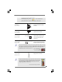
2.3 CPU Installation2.3 CPU Installation
2.3 CPU Installation2.3 CPU Installation
2.3 CPU Installation
For the installation of Intel 775-LAND CPU,
please follow the steps below.
Before you insert the 775-LAND CPU into the socket, please check if
the CPU surface is unclean or if there is any bent pin on the socket.
Do not force to insert the CPU into the socket if above situation is
found. Otherwise, the CPU will be seriously damaged.
Step 1. Open the socket:
Step 1-1. Disengaging the lever by depressing
down and out on the hook to clear
retention tab.
Step 1-2. Rotate the load lever to fully open po-
sition at approximately 135 degrees.
Step 1-3. Rotate the load plate to fully open po-
sition at approximately 100 degrees.
Step 2. Insert the 775-LAND CPU:
Step 2-1. Hold the CPU by the edges where are
marked with black lines.
Step 2-2. Orient the CPU with IHS (Integrated
Heat Sink) up. Locate Pin1 and the two
orientation key notches.
775-Pin Socket Overview
black line
black line
775-Pin Socket
Pin1
alignment key
alignment key
Pin1
orientation
key notch
orientation
key notch
775-LAND CPU

1414
1414
14
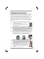
For proper inserting, please ensure to match the two orientation key
notches of the CPU with the two alignment keys of the socket.
Step 2-3. Carefully place the CPU into the socket
by using a purely vertical motion.
Step 2-4. Verify that the CPU is within the socket
and properly mated to the orient keys.
Step 3. Remove PnP Cap (Pick and Place Cap):
Use your left hand index finger and thumb to
support the load plate edge, engage PnP cap
with right hand thumb and peel the cap from the
socket while pressing on center of PnP cap to
assist in removal.
1. It is recommended to use the cap tab to handle and avoid kicking
off the PnP cap.
2. This cap must be placed if returning the motherboard for after
service.
Step 4. Close the socket:
Step 4-1. Rotate the load plate onto the IHS.
Step 4-2. While pressing down lightly on load
plate, engage the load lever.
Step 4-3. Secure load lever with load plate tab
under retention tab of load lever.

1515
1515
15
2.42.4
2.42.4
2.4
Installation of CPU Fan and HeatsinkInstallation of CPU Fan and Heatsink
Installation of CPU Fan and HeatsinkInstallation of CPU Fan and Heatsink
Installation of CPU Fan and Heatsink
This motherboard is equipped with 775-Pin socket that supports Intel 775-LAND CPU.
Please adopt the type of heatsink and cooling fan compliant with Intel 775-LAND CPU
to dissipate heat. Before you installed the heatsink, you need to spray thermal
interface material between the CPU and the heatsink to improve heat dissipation.
Ensure that the CPU and the heatsink are securely fastened and in good contact with
each other. Then connect the CPU fan to the CPU_FAN connector (CPU_FAN1, see
page 10, No. 6).
For proper installation, please kindly refer to the instruction manuals of
your CPU fan and heatsink.
Below is an example to illustrate the installation of the heatsink for 775-LAND CPU.
Step 1. Apply thermal interface material onto center
of IHS on the socket surface.
Step 2. Place the heatsink onto the socket. Ensure
fan cables are oriented on side closest to the
CPU fan connector on the motherboard
(CPU_FAN1, see page 10, No. 6).
Step 3. Align fasteners with the motherboard
throughholes.
Step 4. Rotate the fastener clockwise, then press
down on fastener caps with thumb to install
and lock. Repeat with remaining fasteners.
If you press down the fasteners without rotating them clockwise,
the heatsink cannot be secured on the motherboard.
Step 5. Connect fan header with the CPU fan
connector on the motherboard.
Step 6. Secure excess cable with tie-wrap to ensure
cable does not interfere with fan operation or
contact other components.

1616
1616
16
2.5 Installation of Memor2.5 Installation of Memor
2.5 Installation of Memor2.5 Installation of Memor
2.5 Installation of Memor
y Modules (DIMM)y Modules (DIMM)
y Modules (DIMM)y Modules (DIMM)
y Modules (DIMM)
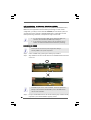
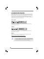
Wolfdale1333-GLAN motherboard provides two 240-pin DDR2 (Double Data Rate 2)
DIMM slots, and supports Dual Channel Memory Technology. For dual channel
configuration, you always need to install two identical (the same brand, speed, size
and chip-type) memory modules in the DDR2 DIMM slots to activate Dual Channel
Memory Technology. Otherwise, it will operate at single channel mode.
1. It is not allowed to install a DDR memory module into DDR2 slot;
otherwise, this motherboard and DIMM may be damaged.
2. If you install only one memory module or two non-identical memory
modules, it is unable to activate the Dual Channel Memory Technology.
Installing a DIMMInstalling a DIMM
Installing a DIMMInstalling a DIMM
Installing a DIMM
Please make sure to disconnect power supply before adding or
removing DIMMs or the system components.
Step 1. Unlock a DIMM slot by pressing the retaining clips outward.
Step 2. Align a DIMM on the slot such that the notch on the DIMM matches the break
on the slot.
The DIMM only fits in one correct orientation. It will cause permanent
damage to the motherboard and the DIMM if you force the DIMM into the
slot at incorrect orientation.
Step 3. Firmly insert the DIMM into the slot until the retaining clips at both ends fully
snap back in place and the DIMM is properly seated.
notch
break
notch
break

1717
1717
17
2.6 Expansion Slots (PCI and PCI Express Slots)2.6 Expansion Slots (PCI and PCI Express Slots)
2.6 Expansion Slots (PCI and PCI Express Slots)2.6 Expansion Slots (PCI and PCI Express Slots)
2.6 Expansion Slots (PCI and PCI Express Slots)
There are 3 PCI slots and 3 PCI Express slots on this motherboard.
PCI slots: PCI slots are used to install expansion cards that have the 32-bit PCI
interface.
PCIE slots: PCIE1 (PCIE x16 slot) is used for PCI Express cards with x16 lane
width graphics cards.
PCIE2 / PCIE3 (PCIE x1 slot) is used for PCI Express cards with x1
lane width cards, such as Gigabit LAN card, SATA2 card, etc.
Installing an expansion cardInstalling an expansion card
Installing an expansion cardInstalling an expansion card
Installing an expansion card
Step 1. Before installing the expansion card, please make sure that the power
supply is switched off or the power cord is unplugged. Please read the
documentation of the expansion card and make necessary hardware
settings for the card before you start the installation.
Step 2. Remove the bracket facing the slot that you intend to use. Keep the screws
for later use.
Step 3. Align the card connector with the slot and press firmly until the card is
completely seated on the slot.
Step 4. Fasten the card to the chassis with screws.

1818
1818
18
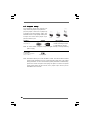
2.7 Jumpers Setup2.7 Jumpers Setup
2.7 Jumpers Setup2.7 Jumpers Setup
2.7 Jumpers Setup
The illustration shows how jumpers are
setup. When the jumper cap is placed on
pins, the jumper is “Short”. If no jumper cap
is placed on pins, the jumper is “Open”. The
illustration shows a 3-pin jumper whose pin1
and pin2 are “Short” when jumper cap is
placed on these 2 pins.
Jumper Setting Description
PS2_USB_PWR1 Short pin2, pin3 to enable
(see p.10 No. 1) +5VSB (standby) for PS/2
or USB wake up events.
Note: To select +5VSB, it requires 2 Amp and higher standby current provided by
power supply.
Clear CMOS
(CLRCMOS1, 2-pin jumper)
(see p.10 No. 9)
Note: CLRCMOS1 allows you to clear the data in CMOS. The data in CMOS includes
system setup information such as system password, date, time, and system
setup parameters. To clear and reset the system parameters to default setup,
please turn off the computer and unplug the power cord from the power
supply. After waiting for 15 seconds, use a jumper cap to short 2 pins on
CLRCMOS1 for 5 seconds.
+5V
1_2
+5VSB
2_3
2-pin jumper

1919
1919
19
2.8 Onboard Headers and Connectors2.8 Onboard Headers and Connectors
2.8 Onboard Headers and Connectors2.8 Onboard Headers and Connectors
2.8 Onboard Headers and Connectors
Onboard headers and connectors are NOT jumpers. Do NOT place
jumper caps over these headers and connectors. Placing jumper
caps over the headers and connectors will cause permanent dam-
age of the motherboard!
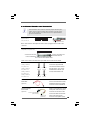
FDD connector
(33-pin FLOPPY1)
(see p.10 No. 22)
Note: Make sure the red-striped side of the cable is plugged into Pin1 side of the
connector.
FLOPPY1
Pin1
the red-striped side to Pin1
connect the black end
to the IDE devices
connect the blue end
to the motherboard
80-conductor ATA 66/100 cable
IDE1
PIN1
connect to the SATA HDD
power connector
connect to the
power supply
SATAII_1
(PORT0)
SATAII_2
(PORT1)
SATAII_3
(PORT2)
SATAII_4
(PORT3)
Serial ATAII Connectors These Serial ATAII (SATAII)
(SATAII_1 (PORT0): connectors support SATAII
see p.10, No. 15) or SATA hard disk for internal
(SATAII_2 (PORT1): storage devices. The current
see p.10, No. 14) SATAII interface allows up to
(SATAII_3 (PORT2): 3.0 Gb/s data transfer rate.
see p.10, No. 12)
(SATAII_4 (PORT3):
see p.10, No. 13)
Serial ATA (SATA) Either end of the SATA data cable
Data Cable can be connected to the SATA /
(Optional) SATAII hard disk or the SATAII
connector on the motherboard.
Serial ATA (SATA) Please connect the black end of
Power Cable SATA power cable to the power
(Optional) connector on each drive. Then
connect the white end of SATA
power cable to the power
connector of the power supply.
Primary IDE connector (Blue)
(39-pin IDE1, see p.10 No. 10)
Note: Please refer to the instruction of your IDE device vendor for the details.

2020
2020
20
USB 2.0 Header Besides six default USB 2.0
(9-pin USB6_7) ports on the I/O panel, there is
(see p.10 No. 21) one USB 2.0 header on this
motherboard. This USB 2.0
header can support two USB
2.0 ports.
DeskExpress Hot Plug Detection This header supports the Hot
Header Plug detection function for
(5-pin IR1) ASRock DeskExpress.
(see p.10 No. 19)
Internal Audio Connector This connector allows you
(4-pin CD1) to receive stereo audio input
(CD1: see p.10 No. 23) from sound sources such as
a CD-ROM, DVD-ROM, TV
tuner card, or MPEG card.
Front Panel Audio Header This is an interface for front
(9-pin HD_AUDIO1) panel audio cable that allows
(see p.10 No. 24) convenient connection and
control of audio devices.
CD-L
GND
GND
CD-R
CD1
J_SENSE
OUT2_L
1
MIC _R ET
PRESENC E#
GND
OUT2_R
MIC2_R
MIC2_L
OUT_R ET
1
IRTX
+5VS B
Hotplug#
IRRX
GND
1. High Definition Audio supports Jack Sensing, but the panel wire on
the chassis must support HDA to function correctly. Please follow the
instruction in our manual and chassis manual to install your system.
2. If you use AC’97 audio panel, please install it to the front panel audio
header as below:
A. Connect Mic_IN (MIC) to MIC2_L.
B. Connect Audio_R (RIN) to OUT2_R and Audio_L (LIN) to OUT2_L.
C. Connect Ground (GND) to Ground (GND).
D. MIC_RET and OUT_RET are for HD audio panel only. You don’t
need to connect them for AC’97 audio panel.
E. Enter BIOS Setup Utility. Enter Advanced Settings, and then select
Chipset Configuration. Set the Front Panel Control option from
[Auto] to [Enabled].
F. Enter Windows system. Click the icon on the lower right hand
taskbar to enter Realtek HD Audio Manager.
For Windows
®
2000 / XP / XP 64-bit OS:
Click “Audio I/O”, select “Connector Settings” , choose
“Disable front panel jack detection”, and save the change by
clicking “OK”.
USB _PWR
USB _PWR
P+5
P-5
P+4
P-4
GND
GND
D UMMY
1
Page is loading ...
Page is loading ...
Page is loading ...
Page is loading ...
Page is loading ...
Page is loading ...
Page is loading ...
Page is loading ...
Page is loading ...
Page is loading ...
Page is loading ...
Page is loading ...
Page is loading ...
Page is loading ...
Page is loading ...
Page is loading ...
Page is loading ...
Page is loading ...
Page is loading ...
Page is loading ...
Page is loading ...
Page is loading ...
-
 1
1
-
 2
2
-
 3
3
-
 4
4
-
 5
5
-
 6
6
-
 7
7
-
 8
8
-
 9
9
-
 10
10
-
 11
11
-
 12
12
-
 13
13
-
 14
14
-
 15
15
-
 16
16
-
 17
17
-
 18
18
-
 19
19
-
 20
20
-
 21
21
-
 22
22
-
 23
23
-
 24
24
-
 25
25
-
 26
26
-
 27
27
-
 28
28
-
 29
29
-
 30
30
-
 31
31
-
 32
32
-
 33
33
-
 34
34
-
 35
35
-
 36
36
-
 37
37
-
 38
38
-
 39
39
-
 40
40
-
 41
41
-
 42
42


ASROCK WOLFDALE1333-GLANR2 Datasheet
- Category
- Motherboards
- Type
- Datasheet
Ask a question and I''ll find the answer in the document
Finding information in a document is now easier with AI
Related papers
-
ASROCK CONROE945PL-GLAN Installation guide
-
ASROCK P41C-DE Owner's manual
-
ASROCK P5B-DE Owner's manual
-
ASROCK A330GC User manual
-
ASROCK 4Core1600-GLAN User manual
-
-
-
ASROCK P43ME Owner's manual
-
ASROCK P43C-ME Owner's manual
-
ASROCK X38TURBOTWINS Owner's manual