
Preface
Preface
Copyright
This publication, including all photographs, illustrations and software, is protected under
international copyright laws, with all rights reserved. Neither this manual, nor any of the
material contained herein, may be reproduced without written consent of the author.
Version 1.0
Disclaimer
The information in this document is subject to change without notice. The manufacturer
makes no representations or warranties with respect to the contents hereof and specifically
disclaims any implied warranties of merchantability or fitness for any particular purpose.
The manufacturer reserves the right to revise this publication and to make changes from
time to time in the content hereof without obligation of the manufacturer to notify any
person of such revision or changes.
Trademark Recognition
Microsoft, MS-DOS and Windows are registered trademarks of Microsoft Corp.
MMX, Pentium, Pentium-II, Pentium-III, Celeron are registered trademarks of Intel Cor-
poration.
Other product names used in this manual are the properties of their respective owners and
are acknowledged.
Federal Communications Commission (FCC)
This equipment has been tested and found to comply with the limits for a Class B digital
device, pursuant to Part 15 of the FCC Rules. These limits are designed to provide reason-
able protection against harmful interference in a residential installation. This equipment
generates, uses, and can radiate radio frequency energy and, if not installed and used in
accordance with the instructions, may cause harmful interference to radio communications.
However, there is no guarantee that interference will not occur in a particular installation.
If this equipment does cause harmful interference to radio or television reception, which
can be determined by turning the equipment off and on, the user is encouraged to try to
correct the interference by one or more of the following measures:
• Reorient or relocate the receiving antenna
• Increase the separation between the equipment and the receiver
• Connect the equipment onto an outlet on a circuit different from that to which
the receiver is connected
• Consult the dealer or an experienced radio/TV technician for help
Shielded interconnect cables and a shielded AC power cable must be employed with this
equipment to ensure compliance with the pertinent RF emission limits governing this
device. Changes or modifications not expressly approved by the system’s manufacturer
could void the user’s authority to operate the equipment.

ii
Preface
Declaration of Conformity
This device complies with part 15 of the FCC rules. Operation is subject to the following
conditions:
• This device may not cause harmful interference, and
• This device must accept any interference received, including interference
that may cause undesired operation
Canadian Department of Communications
This class B digital apparatus meets all requirements of the Canadian Interference-causing
Equipment Regulations.
Cet appareil numérique de la classe B respecte toutes les exigences du Réglement sur le
matériel brouilieur du Canada.
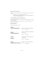
About the Manual
The manual consists of the following:
Chapter 1
Introducing the Motherboard
Chapter 2
Installing the Motherboard
Chapter 3
Using BIOS
Chapter 4
Using the Motherboard Software
Describes features of the motherboard.
Go to
H
page 1
Describes installation of motherboard
components.
Go to
H
page 7
Provides information on using the BIOS
Setup Utility.
Go to
H
page 25
Describes the motherboard software
Go to
H
page 37

iii
TT
TT
T
ABLE OF CONTENTSABLE OF CONTENTS
ABLE OF CONTENTSABLE OF CONTENTS
ABLE OF CONTENTS
Preface i
Chapter 1
1
Introducing the Motherboard 1
Introduction.................................................................................................1
Feature..........................................................................................................2
Motherboard Components........................................................................4
Chapter 2
7 7
7 7
7
Installing the Motherboard 7
Safety Precautions......................................................................................7
Choosing a Computer Case.......................................................................7
Installing the Motherboard in a Case......................................................7
Checking Jumper Settings.........................................................................8
Setting Jumpers..............................................................................8
Checking Jumper Settings..............................................................9
Jumper Settings..............................................................................9
Connecting Case Components...............................................................10
Front Panel Connector.................................................................12
Installing Hardware...................................................................................13
Installing the Processor...............................................................13
Installing Memory Modules.........................................................15
Installing a Hard Disk Drive/CD-ROM/SATA Hard Drive........17
Installing a Floppy Diskette Drive...............................................18
Installing Add-on Cards..............................................................19
Connecting Optional Devices......................................................20
Connecting I/O Devices..........................................................................23
Chapter 3
25 25
25 25
25
Using BIOS 25
About the Setup Utility............................................................................25
The Standard Configuration........................................................25
Entering the Setup Utility..............................................................25
Updating the BIOS.......................................................................26
Using BIOS................................................................................................26
Main Features..............................................................................27
Advanced Features......................................................................28
Power Features............................................................................32

iv
Boot Features...............................................................................33
Exit Features................................................................................35
Chapter 4
37 37
37 37
37
Using the Motherboard Software 37
About the Software CD-ROM................................................................37
Auto-installing under Windows 2000/XP................................37
Running Setup..............................................................................38
Manual Installation..................................................................................40
Utility Software Reference.......................................................................40

1
Introducing the Motherboard
Chapter 1
Introducing the Motherboard
Introduction
Thank you for choosing the 945GCT-HM motherboard. This motherboard is a high perfor-
mance, enhanced function motherboard designed to support the LGA775 socket Intel
Core
TM
2 Duo (E4400/E4300)/Pentium D/Pentium 4/Celeron D processors for high-end
business or personal desktop markets.
The motherboard incorporates the 945GC Northbridge (NB) and ICH7 Southbridge (SB)
chipsets. The Northbridge supports a Front Side Bus (FSB) frequency of 800/533 MHz using
a scalable FSB Vcc_CPU. The memory controller supports DDR2 memory DIMM frequen-
cies of 533/400. It supports two DDR2 Sockets with up to maximum memory of 2 GB.
DDR2 memory bandwidth of 4.3 Gb/s in single-channel is supported, or 8.5 Gb/s in dual-
channel interleaved mode. High resolution graphics via one PCI Express slot, intended for
Graphics Interface, is fully compliant to the PCI Express Base Specification revision 1.0a.
The ICH7 Southbridge supports two PCI slots which are PCI 2.3 compliant. In addition, one
PCI Express x1 slot is supported, fully compliant to the PCI Express Base Specification,
Revision 1.0a. It implements an EHCI compliant interface that provides 480 Mb/s band-
width for six USB 2.0 ports. One onboard IDE connector supports 2 IDE devices in Ultra
ATA 100/66/33 mode. The Southbridge integrates a Serial ATA host controller, supporting
two SATA ports with maximum transfer rate up to 3.0 Gb/s each.
The motherboard is equipped with advanced full set of I/O ports in the rear panel, including
PS/2 mouse and keyboard connectors, one VGA port, two USB ports, one LAN port, audio
jacks for microphone, line-in and line-out.

2
Introducing the Motherboard
Feature
• Supports DDR2 533/400 DDR SDRAM with Dual-channel architecture
• Accommodates two unbuffered DIMMs
• Up to 1 GB per DIMM with maximum memory size up to 2 GB
Memory
• Accommodates Intel Core
TM
2 Duo (E4400/E4300)/Pentium D/Pentium 4/Celeron
D processors
• Supports a system bus (FSB) of 800/533 MHz
• Supports “Hyper-Threading” technology CPU
The motherboard uses an LGA775 type of Intel Core
TM
2 Duo (E4400/E4300)/Pentium
D/Pentium 4/Celeron D that carries the following features:
Processor
“Hyper-Threading” technology enables the operating system into thinking it’s hooked
up to two processors, allowing two threads to be run in parallel, both on separate
“logical” processors within the same physical processor.
ICH7 (SB)
• Enhanced DMA Controller, interrupt controller, and timer func-
tions
• Compliant with PCI Express Base Specification, Revision
1.0a
• Compliant with PCI 2.3 specification
• Integrated SATA 3.0 Gb/s Host Controller
• Integrated USB 2.0 Host Controller
• Integrated IDE controller supports Ultra ATA 100/66/33
The 945GC Northbridge (NB) and ICH7 Southbridge (SB) chipsets are based on an
innovative and scalable architecture with proven reliability and performance.
Chipset
945GC (NB)
• Supports 32-bit host bus addressing, allowing the CPU to
access the entire 2 GB of the memory address space
• 2 Gb/s point-to-point Direct Media Interface (DMI) to ICH7 (1
Gb/s) each direction
• Supports one PCI Express x16 for Graphics Interface, fully
compliant to the PCI Express Base Specification revision
1.0a.
• Supports 256-Mb, 512-Mb and 1-Gb DDR2 technologies for
x8 and x16 devices
• Supports high quality 3D setup, Render Engine and high-
quality texture engine

3
Introducing the Motherboard
The motherboard comes with the following expansion options:
• One PCI Express x16 slot for Graphic Interface
• One PCI Express x1 slot
• Two 32-bit PCI v2.3 compliant slots
• One 40-pin IDE connector that supports two IDE devices
• One floppy disk drive interface
• Two 7-pin SATA connectors
Expansion Options
The motherboard supports UDMA bus mastering with transfer rates of 100/66/33
Mb/s.
The firmware can also be used to set parameters for different processor clock speeds.
• Power management
• Wake-up alarms
• CPU parameters
• CPU and memroy timing
BIOS Firmware
This motherboard uses AMI BIOS that enables users to configure many system
features including the following:
Some hardware specifications and software items are subject to change with
out prior notice.
• Two PS/2 ports for mouse and keyboard
• One VGA port
• Two USB ports
• One LAN port
• Audio jacks for microphone, line-in and line-out
The motherboard has a full set of I/O ports and connectors:
Integrated I/O
Onboard LAN
The onboard LAN controller provides the following features:
• Integrated Fast Ethernet Controller for PCI Express
TM
Applications
• Integrated 10/100 transceiver
• Wake-on-LAN and remote wake-up support
Audio
• 5.1 + 2 Channel High Definition Audio Codec
• All DACs support 192K/96K/48K/44.1KHz DAC sample rate
• High-quality analog differential CD input
• Meets Microsoft WHQL/WLP 3.0 audio requirements
• Direct Sound 3D
TM
compatible

4
Introducing the Motherboard
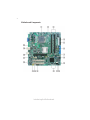
Motherboard Components

5
Introducing the Motherboard
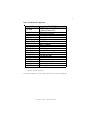
Table of Motherboard Components
* Stands for optional components
This concludes Chapter 1. The next chapter explains how to install the motherboard.
LABEL COMPONENTS
1. CPU Socket
LGA775 socket for Intel Core
TM
2 Duo/Pentium
D/Pentium 4/Celeron D CPUs
2. CPU_FAN
CPU cooling fan connector
3. DIMM1/3
240-pin DDR2 SDRAM slots
4. ATX1
Standard 24-pin ATX power connector
5. FDD
Floppy disk drive connector
6. IDE1
Primary IDE connector
7. CLR_CMOS_HP
Clear CMOS jumper
8. CLR_PWD
Clear Password jumper
9. SATA1~2
Serial ATA connectors
10. F_PANEL
Front panel switch/LED header
11. CLR_CMOS1 *
Clear CMOS jumper
12. F_USB1~2
Front Panel USB headers
13. HD_AUDIO
High definition audio digital header
14. AUX_IN
Auxiliary In connector
15. F_AUDIO1
Front panel audio header
16. PCI2~3
32-bit add-on card slots
17. PCI-E2
PCI Express x1 slot
18. PCIEX16
PCI Express slot for graphics interface
19. SYS_FAN
System cooling fan connector
20. ATX12V Auxiliary 4-pin power connector

6
Introducing the Motherboard
Memo

-
 1
1
-
 2
2
-
 3
3
-
 4
4
-
 5
5
-
 6
6
-
 7
7
-
 8
8
-
 9
9
-
 10
10
-
 11
11


