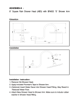
American Standard 8888.054.295 User manual

Category
Sanitary ware
Type
User manual
T038.50X
TROPIC
FINISHED WALL
4"
TOP OF TUB RIM
BOTTOM OF TUB
74" FOR HEAD
CLEARANCE
4-1/4" REF.
18" OPTIONAL
5-1/8" REF.
1/2" NPT
1/2" COPPER
7-5/8”
1-1/2" REF.
6" REF.
"SEE ILLUSTRATION "
3/4"" TO 2-3/8"
SHR
TUB
OPTIONAL TO FINISHED
FLOOR USUALLY
BETWEEN 65'' AND 80''
IN WALL PRESSURE BALANCING
BATH AND SHOWER TRIM KIT
To assure proper positioning in relation to wall,
note roughing-in dimensions.
ROUGHING-IN DIMENSIONS
Certified to comply with ANSI A112.18.1
Installation
Instructions
5VCJOH$VUUFS
4mm (5/32")
Hex Wrench
.
Required Tools
Adjustable Wrench
Channel Locks
Flat Blade Screwdriver
Plumbers' Putty or Caulking
Phillips Screwdriver
)
$
0'
'
with EverClean™ Finish
Congratulations on purchasing your American Standard faucet
with EverClean nish found only on American Standard faucets.
To ensure that your installation proceeds smoothly-please read these
instructions carefully before you begin.
EverClean Finish
• One wipe eortlessly removes spots
• Eliminates the need for cleaners and scrubbing
• Permanent surface protectant remains beautiful for the life of the faucet
• EverClean™ available on: Polished Chrome, Satin Nickel,
Stainless Steel, Polished Brass (or any combination of these nishes)
ADJUST HOT LIMIT STOP
By restricting HANDLE rotation and limiting the amount of hot water allowed to mix with the cold, the HOT LIMIT SAFETY
STOP (1) reduces risk of accidental scalding. To set the maximum hot water temperature of your faucet, all you need to
do is adjust the setting on the HOT LIMIT SAFETY STOP (1).
Turn CARTRIDGE STEM (2) to the OFF position (coldest setting) before making adjustment to
HOT LIMIT STOP (1). Use a flat blade screwdriver to pry free the HOT LIMIT SAFETY STOP (1).
Pull forward and rotate counterclockwise one number to limit hot water temperature. Use
ARROW (3) on CARTRIDGE (4) and NUMBERS (5) on HOT LIMIT STOP (1) for indication.
1
5
1
3
1
1
9
7
5
3
1
1
5
1
3
1
1
9
7
5
3
1
COLDER
(Larger Numbers)
0 1 3 5 7 9 11 13 15
HOTTER
(Smaller Numbers)
0 1 3 5 7 9 11 13 15
1
5
4
3
2
1
5
1
3
1
1
9
7
5
3
1
0
5
4
3
2
1
Install ADAPTER (1) onto VALVE STEM (2) using
SCREW (3).
Align and install HANDLE (4) and tighten with SET SCREW (5)
using 2.5mm Hex Wrench supplied.
Check proper operation of HANDLE (4).
Turn on water supply on and test installed fitting.
Operate valve and diverter spout.
INSTALL HANDLE and TEST FITTING
HEX WRENCH
3
4
)
$
0
''
5
2
1
)
$
0''
INSTALL TRIM
6
9
8
5
5
A
7
3
1
2
4
10
When finished tiling the wall, remove PLASTER GUARD (A)
and turn off water supply.
Push CAP (1) over VALVE CARTRIDGE (2).
Mount ESCUTCHEON (3) and gasket to valve body with SCREWS (4).
Remove PIPE CAP & PLUG (5) from shower pipe and tub filler pipe.
Apply Teflon Tape to both ends of SHOWER ARM (6). Install SHOWER ARM (6)
with FLANGE (8) into shower pipe and tighten.
Thread SHOWER HEAD (7) onto ARM (6) and tighten.
Push SHOWER ARM FLANGE (8) to wall and tighten SET SCREW (9)
with 5/64” hex wrench.
Install SLIP-ON DIVERTER SPOUT (10) onto filler pipe and tighten.
CAUTION: Protect finish on SHOWER ARM,
SHOWER HEAD and TUB SPOUT when installing.
HEX
WRENCH
.
Remove HANDLE (2).
Remove two SCREWS (6) holding ESCUTCHEON (7)
and remvoe ESCUTCHEON (7).
Remove CAP (3), SCREWS (5) and CARTRIDGE (1).
Clean inlets and MANIFOLD (4).
Reassemble CARTRIDGE (1), alternately tightening SCREWS (5).
Replace CAP (3) and HANDLE (2). Check flow.
If faucet drips, operate handle several times
from "off" to "on". Do not apply excessive force.
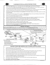
Clogged CARTRIDGE (1) inlets may cause
reduced flow in "full on" hot or cold. To clean
inlets, first turn off water supply, then:
SERVICE

2
7
1
6
5
3
)
$
0
''
4
Remove CARTRIDGE (1) by removing CARTRIDGE SCREWS (2). Remove three SCREWS (3) from
FIXATION RING (4) and pull out PRESSURE BALANCING (5) unit.
Clean SEALS (9) on base of CARTRIDGE (1). Check base of PRESSURE BALANCING UNIT (5) and clean O-RINGS (6).
Remove CAPS (7) and check O-RINGS on inside of CAPS (7). Clean inside sealing surfaces of VALVE BODY (8).
Re-assemble PRESSURE BALANCING UNIT (5) and CARTRIDGE (1). Tighten all screws.
Turn on water supply and see above for installing TRIM and HANDLE.
Remove handle and trim.
SERVICE: VALVE LEAKS WHEN SHUT OFF
BACK TO BACK INSTALLATION
Remove PRESSURE BALANCE UNIT (5).
Remove CAPS (7) and clean valve thoroughly.
Examine balancing unit and check condition of O-ring on end of piston. Piston should move back and forth.
Order Repair Part M952100-0070A if balancing unit is defective.
Replace CAPS (7) and install PRESSURE BALANCE UNIT (5). Make sure inlets line up with two holes in bottom
of casting. Top flange should butt-up against top of casting.
Remove PRESSURE BALANCE UNIT (5). Rotate PRESSURE BALANCE UNIT (5) 180˚ so that the inlets face up
and the large outlet port faces down.
Push PRESSURE BALANCE UNIT (5) in casting make sure inlets line up with holes in bottom of casting.
Top flange should butt up against top of casting.
Reassemble FIXATION RING (4) and CARTRIDGE (1).
UNABLE TO MAINTAIN CONSTANT TEMPERATURE
BACK TO BACK INSTALLATION
ROTATE 180˚
1
2
9
5
5
7
8
6
4
3
INLETS
LARGE OUTLET
EverClean™ Finish Care Instructions
American Standard’s EverClean finish will wipe clean with a soft, dry cloth. A soft cloth with
clean water may also be used, if desired. No additional cleaning products are required.
DO NOT USE: Soaps, acid, polish, abrasives, harsh cleaners, or a cloth with a coarse surface.
.
  • Page 1 1
  • Page 2 2
  • Page 3 3

American Standard 8888.054.295 User manual

Category
Sanitary ware
Type
User manual

Ask a question and I''ll find the answer in the document

Finding information in a document is now easier with AI