Ducane 95G1E Installation guide
- Category
- Water heaters & boilers
- Type
- Installation guide

508034-02 Issue 2135 Page 1 of 49
SERVICE MANUAL
95G1UHEX Gas Furnace
(P) 508034-02
*P508034-02*
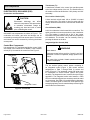
This is a safety alert symbol and should never be ignored. When you see this symbol on labels or in manuals, be alert to
the potential for personal injury or death.
Electric shock hazard.
Can cause injury or death. Before attempting
to perform any service or maintenance,
turn the electrical power to unit OFF at
disconnect switch(es). Unit may have
multiple power supplies.
WARNING
As with any mechanical equipment, contact with sharp
sheet metal edges can result in personal injury. Take
care while handling this equipment and wear gloves
and protective clothing.
CAUTION
Improper installation, adjustment, alteration, service
or maintenance can cause property damage, personal
injury or loss of life. Installation and service must be
performed by a licensed professional HVAC installer (or
equivalent), service agency or the gas supplier.
WARNING
95G1UHEX series units are high-eciency gas furnaces
available in heating input capacities of 40,000 to 100,000
Btuh and cooling applications from 2 through 5 tons. Refer
to Engineering Handbook for proper sizing.
Units are factory equipped for use with natural gas. All
95G1UHEX units are equipped with a hot surface ignition
system. The gas valve is redundant to assure safety shut-
o as required by C.S.A.
The heat exchanger, burners and manifold assembly can
be removed for inspection and service. The maintenance
section gives a detailed description on how this is done.
All specications are subject to change. Procedures
outlined in this manual are presented as a recommendation
only and do not supersede or replace local or state codes.
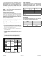
Table of Contents
Technical Specications ..............................................2
Blower Performance ....................................................3
Parts Arrangement.......................................................5
Unit Components .........................................................6
Placement and Installation ........................................15
Joint Cementing Procedure .......................................16
Venting Practices ....................................................... 16
Vent Piping Guidelines ..............................................17
Start-Up .....................................................................37
Heating System Service Checks ...............................38
Typical Operating Characteristics .............................. 41
Maintenance ..............................................................42
Wiring Diagram and Sequence of Operation ............. 45

508034-02Issue 2135Page 2 of 49
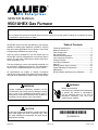
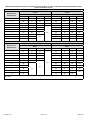
Physical and Electrical Data
Model Input
(Btuh)
Output
(Btuh)
AFUE
(ICS)
Nominal
Cooling
Capacity
Gas
Inlet
(in.)
Volts/
Hz/
Phase
Max. Time
Delay
Breaker or
Fuse
Nominal
Full Load
Amps
Trans
(VA)
Approx
Shipping
Weight
(lbs)
95G1UH040BE12X 40,000 39,000 95% 3 Ton 1/2 120-60-1 15 6.8 40 122
95G1UH060BE12X 60,000 58,000 95% 3 Ton 1/2 120-60-1 15 6.8 40 128
95G1UH080CE16X 80,000 78,000 95% 4 Ton 1/2 120-60-1 15 8.4 40 148
95G1UH100CE20X 100,000 97,000 95% 5 Ton 1/2 120-60-1 15 10.9 40 157
NOTE: For vent length and clearances to combustibles, please reference installation instructions.
Technical Specications
Accessory List
Catalog Number Description
External Filter Rack Kits
1.841018 1 pack (16 x 25)
1.841039 10 pack (16 x 25)
Return Air Base
68W62 17.5" B Width
68W63 21.0" C Width
Horizontal Suspension Kit
51W10 80% & 90% Kit
Flush Mount Termination (90% Furnaces only) US Only
51W11 2" & 3" Vent Version
Concentric Vent Kit (90% Furnaces only) US Only
71M80 1-1/2" Vent Version
69M29 2" Vent Version
60L46 3" Vent Version
Twinning Kit
16W72 Constant Torque Gas Furnace Twinning Kit
LP/Propane Conversion Kit
19K05 -060 Capacity Models Only
19K06 -080 Capacity Models Only

508034-02 Issue 2135 Page 3 of 49
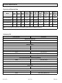
Blower Performance
95G1UH040BE12X Performance (Less Filter)
External
Static
Pressure
in. w.c.
Air Volume / Watts at Various Blower Speeds
High Medium-High Medium Medium-Low Low
cfm Watts cfm Watts cfm Watts cfm Watts cfm Watts
0.00 1450 350 1280 247 1190 200 966 112 902 89
0.10 1429 360 1268 257 1171 207 939 119 875 99
0.20 1400 371 1248 267 1139 212 894 124 850 110
0.30 1377 381 1222 279 1112 223 872 131 800 114
0.40 1350 391 1195 286 1084 235 829 138 778 122
0.50 1317 401 1156 298 1043 240 794 147 724 129
0.60 1285 408 1127 308 1019 252 754 151 690 142
0.70 1233 390 1107 316 987 259 708 161 633 144
0.80 1160 370 1077 322 955 270 661 167 607 149
95G1UH060BE12X Performance (Less Filter)
External
Static
Pressure
in. w.c.
Air Volume / Watts at Various Blower Speeds
High Medium-High Medium Medium-Low Low
cfm Watts cfm Watts cfm Watts cfm Watts cfm Watts
0.00 1477 338 1289 240 1189 188 940 99 905 88
0.10 1431 353 1262 254 1160 200 918 109 873 97
0.20 1401 360 1244 263 1135 209 894 121 839 108
0.30 1372 374 1215 270 1110 221 852 126 798 113
0.40 1352 387 1189 282 1074 226 821 136 772 123
0.50 1324 391 1165 292 1050 241 786 146 728 130
0.60 1296 403 1130 302 1011 252 741 150 691 140
0.70 1255 406 1102 313 988 258 703 161 641 144
0.80 1190 386 1073 326 962 267 664 167 606 153
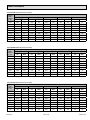
95G1UH080CE16X Performance (Less Filter)
External
Static
Pressure
in. w.c.
Air Volume / Watts at Various Blower Speeds
High Medium-High Medium Medium-Low Low
cfm Watts cfm Watts cfm Watts cfm Watts cfm Watts
0.00 1702 381 1502 270 1375 195 1298 169 1189 132
0.10 1688 418 1479 287 1349 220 1258 187 1136 144
0.20 1660 443 1450 304 1321 242 1215 203 1084 158
0.30 1627 458 1403 321 1282 255 1172 215 1030 172
0.40 1577 475 1370 337 1234 272 1131 231 990 188
0.50 1540 483 1329 352 1191 288 1085 245 933 195
0.60 1441 457 1291 369 1146 301 1045 259 883 203
0.70 1293 402 1249 380 1102 315 992 271 830 216
0.80 1144 365 1122 351 1053 326 951 285 809 219

508034-02Issue 2135Page 4 of 49
95G1UH100CE20X Performance (Less Filter)
External
Static
Pressure
in. w.g.
Air Volume / Watts at Dierent Blower Speeds
Bottom Return Air, Side Return Air with Optional Return Air
Base, Return Air from Both Sides or Return Air from Bottom and
One Side.
Single Side Return Air − Air volumes in bold require eld fabricated
transition to accommodate 20 x 25 x 1 in. air lter in order to maintain
proper air velocity.
High Med-High Medium Med-Low Low High Med-High Medium Med-Low Low
cfm Watts cfm Watts cfm Watts cfm Watts cfm Watts cfm Watts cfm Watts cfm Watts cfm Watts cfm Watts
0.00 2156 722 1922 497 1723 370 1589 215 1420 211 2102 118 1833 489 1688 170 1590 300 1375 209
0.10 2112 738 1851 511 1681 388 1552 326 1380 227 2064 730 1809 504 1658 384 1540 314 1347 224
0.20 2076 748 1808 533 1636 403 1525 334 1340 244 2038 749 1789 514 1623 402 1507 331 1325 242
0.30 2035 768 1782 542 1604 425 1488 349 1290 259 2011 760 1761 531 1594 413 1472 348 1266 246
0.40 2009 772 1749 558 1572 433 1441 362 1248 266 1968 770 1726 549 1561 431 1435 355 1247 264
0.50 1942 776 1715 580 1533 452 1424 374 1213 281 1920 776 1685 560 1527 443 1394 374 1199 278
0.60 1881 746 1681 584 1512 468 1357 382 1157 293 1849 741 1660 578 1489 455 1356 379 1154 286
0.70 1790 715 1634 599 1459 474 1319 401 1136 306 1777 723 1622 593 1439 473 1317 395 1124 301
0.80 1702 679 1582 613 1432 491 1300 418 1084 312 1682 681 1588 602 1407 488 1288 408 1067 308

508034-02 Issue 2135 Page 5 of 49
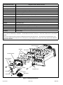
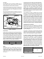
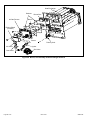
Parts Arrangement
Ignition Control
Ignition Control
Gas Pipe Inlet
(right side only)
Intake Air Pipe
Exhaust Pipe
Heat Exchanger
Burner Assembly
Inlet Air Assembly
Rollout Switch
Gas Valve
Combustion
Air Inducer
Figure 1.

508034-02Issue 2135Page 6 of 49
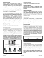
Unit Components
ELECTROSTATIC DISCHARGE (ESD)
Precautions and Procedures
Electrostatic discharge can aect
electronic components. Take precautions
to neutralize electrostatic charge by
touching your hand and tools to metal
prior to handling the control.
CAUTION
95G1UHEX unit components are shown in Figure 1. The
combustion air inducer, gas valve and burners can be
accessed by removing the outer access panel. The blower
and control box can be accessed by removing the blower
access panel.
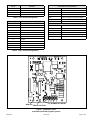
Control Box Components
Unit transformer (T1) and integrated ignition control (A92)
are located in the control box. In addition, a door interlock
switch (S51) is located in the control box See Figure 2.
Figure 2. Control Box
Integrated Control
Door Interlock
Switch
Transformer
Circuit Breaker
Transformer (T1)
A transformer located in the control box provides power
to the low voltage section of the unit. The transformers on
all models are rated at 40VA with a 120V primary and 24V
secondary.
Door Interlock Switch (S51)
A door interlock switch rated 14A at 120VAC is located
on the control box. The switch is wired in series with line
voltage. When the blower door is removed the unit will shut
down.
Circuit Breaker (CB8)
A 24V circuit breaker is also located in the control box. The
switch provides overcurrent protection to the transformer
(T1). The breaker is rated at 3A at 32V. If the current
exceeds this limit the breaker will trip and all unit operation
will shutdown. The breaker can be manually reset by
pressing the button on the face.
Integrated Ignition Control (A92)
Shock hazard.
Disconnect power before servicing. Control is not eld
repairable. If control is inoperable, simply replace entire
control.
Can cause injury or death. Unsafe operation will result
if repair is attempted.
WARNING
The hot surface ignition control system consisting of
an integrated control (Figure 3 with control terminal
designations in Table 1 through Table 3), sensor and
ignitor (Figure 4). The integrated control and ignitor work
in combination to ensure furnace ignition and ignitor
durability. The integrated control, controls all major furnace
operations. The integrated control also features a RED
LED for troubleshooting and two accessory terminals rated
at (1) one amp. See Table 4 for troubleshooting diagnostic
codes. The nitride ignitor is made from a non-porous, high
strength proprietary ceramic material that provides long life
and trouble free maintenance.

508034-02 Issue 2135 Page 7 of 49
Pin # Function
1 Combustion Air Inducer Line
2 Ignitor Line
3 Combustion Air Inducer Neutral
4 Ignitor Neutral
Table 1. 4-Pin Terminal Designation
Pin # Function
1 High Limit Output
2 Not Used
3 24V Line
4 Not Used
5 Rollout Switch Out
6 24V Neutral
7 High Limit Input
8 Ground
9 Gas Valve Common
10 Pressure Switch In
11 Rollout Switch In
12 Gas Valve Out
Table 2. 12-Pin Terminal Designations
1/4” Quick Connect Terminals
120HUM Humidier 120VAC
LINE 120VAC
XFMR Transformer 120VAC
CIRC Indoor blower 120VAC
EAC Indoor air quality accessory 120VAC
NEUTRALS Common 120VAC
HUM24 Humidier 24VAC
3/16” Quick Connect Terminals
COOL Cooling tap 24VAC
HEAT Heating tap 24VAC
FAN Continuous blower 24VAC
PARK (no power) Park terminal for speed taps
FS Flame sense
24 COM Common 24VAC
Table 3.
BLOWER OFF DELAY
RED LED RECALL BUTTON
Figure 3. Integrated Control
(Automatic Hot Surface Ignition System)

508034-02Issue 2135Page 8 of 49
Red LED Flash Code2Diagnostic Codes / Status of Furnace
O No power to control or board fault detected
On Board fault detected
Heartbeat1Control powered - displayed during all modes of operation if no errors are detected
1 ash Reverse line voltage polarity
2 ashes Improper earth ground
3 ashes Burner failed to light, or lost ame during heating demand
4 ashes Low ame signal - check ame sensor
5 ashes Watchguard - burner failed to light, exceeded maximum number or retries or recycles
6 ashes Not used
7 ashes Primary or secondary limit open or Watchguard mode - limit switch open longer than 3 minutes
8 ashes Rollout switch open
9 ashes Pressure switch failed to close of opened during heat demand
10 ashes Watchguard - pressure switch opened 5 times during one heat demand
11 ashes Pressure switch stuck closed prior to activation or combustion air inducer
12 ashes Flame sensed without gas valve energized
13 ashes Low line voltage
1 A “Heartbeat” is indicated by a “Slow Flash” - 1 sec on 1 sec o, repeating
2 Error codes are indicated by a “rapid ash” - the LED ashes X times at ½ second on ½ second o, remains o for 3 seconds then
repeats.
Last 10 error codes are stored in memory including when power is shut o to the unit. - To recall, press and release button, most
recent will be displayed rst, LED o for 3 sec, then next error code is displayed, etc. To clear error codes, depress and hold button
longer than 5 seconds.
Table 4. Diagnostic Codes
Gas Valve
Primary Limit
Ignitor
Sensor
Gas Orifice
Air Orifice
Rollout Switch
(location)
Air Gas Plenum
Gaskets
Burner
Heat Exchanger
Burner Box
Figure 4. Heating Components

508034-02 Issue 2135 Page 9 of 49
Electronic Ignition
On a call for heat the integrated control monitors the
combustion air inducer pressure switch. The control board
will not begin the heating cycle if the pressure switch is
closed (by-passed). Once the pressure switch is determined
to be open, the combustion air inducer is energized. When
the dierential in the pressure switch is great enough, the
pressure switch closes and a 15-second pre-purge begins.
If the pressure switch is not proven within 2-1/2 minutes,
the integrated control goes into Watchguard-Pressure
Switch mode for a 5-minute re-set period.
After the 15-second pre-purge period, the ignitor warms
up for 20 seconds during which the gas valve opens at
19 seconds for a 4-second trial for ignition. The ignitor
remains energized for the rst 3 seconds during the 4
second trial. If ignition is not proved during the 4-second
period, the integrated control will try four more times with
an inter purge and warm-up time between trials of 35
seconds. After a total of ve trials for ignition (including the
initial trial), the integrated control goes into Watchguard-
Flame Failure mode. After a 60-minute reset period, the
integrated control will begin the ignition sequence again.
Fan Time Control
Heating Fan On Time
The fan on time of 30 seconds is not adjustable.
Heating Fan O Time
Fan o time (time that the blower operates after the heat
demand has been satised) can be adjusted by moving
the jumper to a dierent setting. The unit is shipped with
a factory fan o setting of 90 seconds. For customized
comfort, monitor the supply air temperature once the heat
demand is satised. Note the supply air temperature at the
instant the blower is de-energized.
Adjust the fan-o delay to achieve a supply air temperature
between 90° - 110° at the instant the blower is de-energized.
(Longer delay times allow for lower air temperature, shorter
delay times allow for higher air temperature). See Figure 5.
To adjust fan-off timing, reposition jumper across pins to
achieve desired setting.
NO JUMPER
60
90
120
180
60
90
120
180
60
90
120
180
60
90
120
180
60 Second
off Time
90 Second
off Time
120 Second
off Time
180 Second
off Time
Figure 5. Heat Fan-O Time in Seconds
Cooling Fan On Time
The fan on time is 2 seconds and is not adjustable.
Cooling Fan O Time
The control has a 45 second fan o delay after cooling
demand has been met. This delay is factory set and not
adjustable.
Heating Components
Combustion air inducer (B6), primary limit control (S10),
ignitor, burners, ame rollout switch (S47), gas valve
(GV1), combustion air pressure switch (S18), and heat
exchangers are located in the heating compartment. The
heating compartment can be accessed by removing the
outer access panel.
Thermal Switch
The auto-reset switch is located on the front of the air
gas intake. The switch will safely shut the unit down if
excessive temperatures are detected. When the switch
senses excessive temperature, the circuit breaks and the
ignition control immediately stops ignition and closes the
gas valve. See Figure 4.
Burner and Orice
Burners are factory set and require no adjustment. Always
operate the unit with air gas plenum in place. The burner
has one orice located between the gas valve and the air
intake assembly (Figure 4). To check or replace the orice
remove the black iron inlet pipe from the gas valve then
remove the four screws securing the gas valve to the
intake air pipe. The orice is located in the orice housing.
The burner uses an orice (see Table 5) that is precisely
matched to the burner input. The burner can be removed
for service. If burner has been removed, it is critical to
replace all gaskets.
Unit Input Orice Size
040 0.0472
060 0.0595
080 0.0689
100 0.0810
Table 5. Gas Orice
Primary Limit Control
The primary limit (S10) is located in the heating vestibule
panel. When excess heat is sensed in the heat exchanger,
the limit will open. If the limit is open, the furnace control
energizes the supply air blower and closes the gas valve.
The limit automatically resets when unit temperature
returns to normal. The switch must reset within three
minutes or the control will go into Watch guard for one
hour. The switch is factory set and cannot be adjusted. The
switch may have a dierent set point for each unit model
number.

508034-02Issue 2135Page 10 of 49
Test 1
Meter
(set to ohms)
Remove 5-pin plug from control
Check ohms reading across terminals 1 and 5
Ohm value should be between 39 - 70.
Integrated control detail
Test 2
Seperate the 2-pin jack plug near the manifold
and check resistance of the ignitor. If the reading
is correct, then then there is a problem with the
wiring between the jack plug and control. If the
reading is not correct the issue is the ignitor.
Meter
(set to ohms)
Test 3
Insert meter probes into the terminals 1 and 5. (Use small
diameter probes in order to not damage plug). Check
voltage during 20 second warm up period. Voltage should
read 120 volts + 10%. If voltage is above these values,
check for correct supply voltage to furnace.
Integrated control detail
Integrated control detail
Meter
(set to AC volts)
Figure 6. Ignitor Check Out
(exploded view for clarity)

508034-02 Issue 2135 Page 11 of 49
Gas Valve
The 95G1UHEX uses an internally redundant valve to
assure safety shut-o. If the gas valve must be replaced,
the same type valve must be used. See Figure 7.
24VAC terminals and gas control switch are located on top
of the valve. All terminals on the gas valve are connected to
wires from the ignition control. 24V applied to the terminals
opens the valve.
Inlet and outlet pressure taps are located on the valve. A
manifold adjustment screw is also located on the valve. An
LP/Propane changeover kit is available.
NEGATIVE AIR
PRESSURE PORT POSITIVE AIR
PRESSURE PORT
MANIFOLD
PRESSURE TAP
INLET OUTLET
SUPPLY
PRESSURE
TAP
GAS VALVE SHOWN IN THE ON POSITION
Figure 7. Gas Valve
Flame Sensor
A ame sensor is located on the top of the air gas plenum.
The sensor can be removed for service without removing
the the burner. During operation, ame is sensed by
current passed through the ame and sensing electrode.
The SureLight control allows the gas valve to remain open
as long as ame signal is sensed. To check ame sense
signal use the push-button found on the integrated control
and go to Field Test Mode. The menu will display the ame
signal. See Table 6 for ame signal. See Figure 4.
Flame Signal in Microamps
Normal Low Drop Out
2.6 or greater 2.5 or less 1.1
Table 6.
Ignitor
95G1UHEX units use a nitride ignitor made from a
proprietary ceramic material. To check ignitor, measure its
resistance and voltage. A value of 39 to 70 ohms indicates
a good ignitor. Voltage to the ignitor should be 102 -
132VAC. See Figure 6 for resistance and voltage checks.
See Figure 4.
Combustion Air Inducer (B6) & Cold End Header Box
All 95G1UHEX units use a combustion air inducer to move
air through the burners and heat exchanger during heating
operation (see Figure 8). The blower uses a shaded pole
120VAC motor. The motor operates during all heating
operation and is controlled by integrated control A92.
Blower operates continuously while there is a call for heat.
The integrated control will not proceed with the ignition
sequence until combustion air inducer operation is sensed
by the proving switches.
The combustion air inducer is installed on the cold end
header box. The cold end header box is a single piece made
of hard plastic. The box has an internal channel where the
combustion air inducer creates negative pressure at unit
start up. The channel contains an orice used to regulate
ow created by the combustion air inducer. The box has
pressure taps for the combustion air inducer pressure
switch hoses. The pressure switch measures the pressure
across the combustion air inducer orice or dierence in
the channel and the box. If replacement is necessary the
gaskets used to seal the box to the vestibule panel and the
combustion air inducer to the box, must also be replaced.
Combustion Air Prove Switch
95G1UHEX series units are equipped with a dierential
pressure switch located on the cold end header box. The
switch monitors across the combustion air inducer orice
to insure proper ow through the heat exchanger. See
Figure 8 and Figure 9.
The switch is a SPST N.O. pressure switch electrically
connected to the integrated control. The purpose of the
switch is to prevent burner operation if the combustion air
inducer is not moving enough air for proper combustion.
On start-up, the switch monitors whether the combustion
air inducer is operating. It closes a circuit to the integrated
control when the dierence in pressure across the
combustion air inducer orice exceeds a non-adjustable
factory setting. If the switch does not successfully sense
the required dierential, the switch cannot close and the
furnace cannot operate. If the ue or air inlet become
obstructed during operation, the switch senses a loss of
pressure dierential and opens the circuit to the integrated
control. If the condensate line is blocked, water will back
up into the header box and reduce the pressure dierential
across the switch. The pressure switch opens if the
dierential drops below the set point. See Table 7.
Unit Input Orice Size
040
0.50”
060
080
100
Table 7.

508034-02Issue 2135Page 12 of 49
Prove Switch
Combustion Air Inducer
Figure 8. Combustion Air Inducer and Prove Switch
Figure 9. Pressure Switch
Blower Compartment
Each blower is statically and dynamically balanced as
an assembly before installation in the unit.
IMPORTANT
95G1UHEX units are equipped with a constant torque
ECM motor. It has a DC motor coupled to an electronic
control module both contained in the same motor housing.
The motor is programmed to provide constant torque at
each of the ve selectable speed taps. Each tap requires
24 volts to energize.
Input Voltage Requirements
The circuit is designed to be operated with AC voltage. To
enable a tap requires 12 to 33VAC. Expected current draw
will be less than 20mA.
Troubleshooting the Motor
Troubleshooting the motor is an easy process. Follow
steps below.
1. Shut o power to unit.
2. Remove input plugs P48 and P49 from motor. See
Figure 17 for troubleshooting procedure.
If correct voltage is present in tests 1 and 2 and motor is
not operating properly, replace motor. The motor is not eld
repairable.
If replacing the indoor blower motor or blower wheel is
necessary, placement is critical. The blower wheel must
be centered in the blower housing as shown in Figure 10.
When replacing the indoor blower motor the set screw
must be aligned and tightened with the motor shaft as
shown in Figure 11.
Center Blower Wheel
in Blower Housing
Figure 10. Blower Wheel Replacement
Set Screw
Housing Hub
ALIGN AND TIGHTEN SET SCREW WITH
FLAT SIDE OF MOTOR SHAFT
Motor
Shaft
Figure 11.
Secondary Limits
Figure 12. Secondary Limit Control
Replacing the Motor Module
1. Disconnect electrical power to unit.
2. Remove unit access panel.
3. Unplug the two harnesses from the motor control
module. See Figure 13.

508034-02 Issue 2135 Page 13 of 49
TWO HARNESS
CONNECTIONS
MOTOR CONTROL MODULE
MOTOR
Figure 13. Unplug the Two Harness Connection
4. Remove the two hex head bolts securing the motor
control module to the motor (see Figure 14).
REMOVE BOTH HEX
HEAD BOLTS
Figure 14. Remove the Hex Head Bolts
5. Slide the motor control module away from the motor
to access and disconnect the internal three wire
connector. It is not necessary to remove blower motor
itself. Set both hex head bolts aside.
Testing the Motor
See Figure 15.
If any motor fails the below tests, do not install the new
control module. The motor is defective and it also must be
replaced. The new control can fail if placed on a defective
motor.
Figure 15. Motor Test
1. Using an ohmmeter check the resistance from any
one of the motor connector pins to the aluminum end
plate of the motor. This resistance should be greater
than 100k ohms.
2. Check the resistances between each of the three motor
connector pins. These should all read approximately
the same resistance within an ohm.
3. Check to see if the blower wheel spins freely.
Scale Measurement Range
in Words in ohms
2 M two megohm-two million ohms 0 - 2,000,000
200 K two hundred kilo-ohm-two
hundred thousand ohms
0 - 200,000
20 K twenty kilo-ohm-twenty thousand
ohms
0 - 20,000
2 K two kilo-ohm two-thousand ohms 0 - 2,000
200 two hundred ohms 0 - 200
Table 8. Ohm Meter Range
Motor Module Installation
All replacement motor control modules look similar;
however, each module is designed for a specic motor
size. It is very important to make sure that you are using the
correct replacement motor control module. USE OF THE
WRONG MOTOR CONTROL MODULE MAY RESULT IN
UNEXPECTED UNIT OPERATION.
1. Verify electrical power to unit is disconnected.
2. Connect three-wire harness from
motor to control module.
3. Mount new motor control module
to motor using two hex head bolts
removed in Figure 14. Torque
bolts to 22 inch pounds or 1/16th
clock turn as exampled to the
right.
12
3
4
5
6
7
8
9
10
11 12
1/16
TURN
4. Reconnect the two harnesses to the motor control
module.
5. The electrical connectors of the motor should be
facing down to form a drip loop (Figure 16). This will
directs moisture away from the motor and its electric
connections on the motor.
CONNECTOR
ORIENTATION
BETWEEN 4 AND 8
O'CLOCK
BACK OF CONTROL
MODULE
DRIP LOOP
Figure 16. Drip Loop

508034-02Issue 2135Page 14 of 49
1
2
3
4
5
C
L
G
N
Multi−Meter
(set to VAC)
P48
P49
120
Turn on power to unit. Check for 120 volts across terminals
“L” and “N” on input plug P48. If voltage is present, continue
upstream of plug P48 and proceed to test 3.
1
2
3
4
5
C
L
G
N
Multi−Meter
(set to VAC)
P48
P49 24
Switch thermostat to CONTINUOUS FAN MODE. Check for
24 volts across terminal “C” on input plug P48 and speed tap
used for continuous fan. (1, 2, 3, 4 or 5) on input plug P49. If
24 volts is not present, problem may be up stream of plug P49.
Proceed to test 4.
Multi−Meter
(set to VAC)
24
Multi−Meter
(set to VAC)
Check for 120 volts across terminals “CIRC” and “Neutrals”
on the integrated control. If voltage is present, problem is
with the harness. If voltage is not present, problem may be
with the integrated control.
Test 1
Test 2
Test 3 (if necessary)
Test 4 (if necessary)
to test 2. If voltage is not present, problem may be
120
Check for 24 volts across terminals “24 COM” and “FAN”
terminals on the integrated control. If voltage is present,
problem is with the harness. If voltage is not present,
problem may be with the integrated control.
Figure 17.

508034-02 Issue 2135 Page 15 of 49
Placement and Installation
Pipe & Fittings Specications
All pipe, ttings, primer and solvent cement must conform
with American National Standard Institute and the American
Society for Testing and Materials (ANSI/ASTM) standards.
The solvent shall be free owing and contain no lumps,
undissolved particles or any foreign matter that adversely
aects the joint strength or chemical resistance of the
cement. The cement shall show no gelation, stratication,
or separation that cannot be removed by stirring. Refer to
Table 9 for approved piping and tting materials.
Table 9. Piping and Fittings Specications
Schedule 40 PVC (Pipe) D1785
Schedule 40 PVC (Cellular Core Pipe) F891
Schedule 40 PVC (Fittings) D2466
Schedule 40 CPVC (Pipe) F441
Schedule 40 CPVC (Fittings) F438
SDR-21 PVC or SDR-26 PVC (Pipe) D2241
SDR-21 CPVC or SDR-26 CPVC (Pipe) F442
Schedule 40 ABS Cellular Core DWV
(Pipe) F628
Schedule 40 ABS (Pipe) D1527
Schedule 40 ABS (Fittings) D2468
ABS-DWV (Drain Waste & Vent)
(Pipe & Fittings) D2661
PVC-DWV (Drain Waste & Vent)
Pipe & Fittings) D2665
PRIMER & SOLVENT CEMENT ASTM
SPECIFICATION
PVC & CPVC Primer F656
PVC Solvent Cement D2564
CPVC Solvent Cement F493
ABS Solvent Cement D2235
PVC/CPVC/ABS All Purpose Cement For
Fittings & Pipe of the same material
D2564, D2235,
F493
ABS to PVC or CPVC Transition Solvent
Cement D3138
CANADA PIPE & FITTING & SOLVENT
CEMENT MARKING
PVC & CPVC Pipe and Fittings
ULCS636PVC & CPVC Solvent Cement
ABS to PVC or CPVC Transition Cement
POLYPROPYLENE VENTING SYSTEM ULC-S636
PolyPro® by Duravent
InnoFlue® by Centrotherm ULC-S636
ECCO Polypropylene VentTM ULC-S636
Solvent cements for plastic pipe are ammable liquids
and should be kept away from all sources of ignition.
Do not use excessive amounts of solvent cement when
making joints. Good ventilation should be maintained to
reduce re hazard and to minimize breathing of solvent
vapors. Avoid contact of cement with skin and eyes.
CAUTION
95G1UHEX exhaust and intake connections are made
of PVC. Use PVC primer and solvent cement when
using PVC vent pipe. When using ABS vent pipe, use
transitional solvent cement to make connections to the
PVC ttings in the unit.
IMPORTANT
Use PVC primer and solvent cement or ABS solvent
cement meeting ASTM specications, refer to Table 9.
As an alternate, use all purpose cement, to bond ABS,
PVC, or CPVC pipe when using ttings and pipe made of
the same materials. Use transition solvent cement when
bonding ABS to either PVC or CPVC.
Low temperature solvent cement is recommended during
cooler weather. Metal or plastic strapping may be used for
vent pipe hangers. Uniformly apply a liberal coat of PVC
primer for PVC or use a clean dry cloth for ABS to clean
inside socket surface of tting and male end of pipe to
depth of tting socket.
Canadian Applications Only - Pipe, ttings, primer and
solvent cement used to vent (exhaust) this appliance
must be certied to ULC S636 and supplied by a single
manufacturer as part of an approved vent (exhaust)
system. In addition, the rst three feet of vent pipe from the
furnace ue collar must be accessible for inspection.
NOTE: The intake coupling on the furnace is ABS material.
Use transitional solvent to make connections to PVC pipe.
NOTE: Exhaust coupling must be installed with provided
appliance adapter. See Figure 20.

508034-02Issue 2135Page 16 of 49
Joint Cementing Procedure
All cementing of joints should be done according to the
specications outlined in ASTM D 2855.
DANGER OF EXPLOSION!
Fumes from PVC glue may ignite during system check.
Allow fumes to dissipate for at least 5 minutes before
placing unit into operation.
DANGER
1. Measure and cut vent pipe to desired length.
2. Debur and chamfer end of pipe, removing any ridges
or rough edges. If end is not chamfered, edge of pipe
may remove cement from tting socket and result in a
leaking joint.
NOTE: Check the inside of vent pipe thoroughly for
any obstruction that may alter furnace operation.
3. Clean and dry surfaces to be joined.
4. Test t joint and mark depth of tting on outside of pipe.
5. Uniformly apply a liberal coat of PVC primer for PVC
or use a clean dry cloth for ABS to clean inside socket
surface of tting and male end of pipe to depth of tting
socket.
NOTE: Time is critical at this stage. Do not allow
primer to dry before applying cement.
6. Promptly apply solvent cement to end of pipe and
inside socket surface of tting. Cement should be
applied lightly but uniformly to inside of socket. Take
care to keep excess cement out of socket. Apply
second coat to end of pipe.
7. Immediately after applying last coat of cement to pipe,
and while both inside socket surface and end of pipe
are wet with cement, forcefully insert end of pipe into
socket until it bottoms out. Turn PVC pipe 1/4 turn
during assembly (but not after pipe is fully inserted) to
distribute cement evenly. DO NOT turn ABS or cellular
core pipe.
NOTE: Assembly should be completed within 20
seconds after last application of cement. Hammer
blows should not be used when inserting pipe.
8. After assembly, wipe excess cement from pipe at end
of tting socket. A properly made joint will show a bead
around its entire perimeter. Any gaps may indicate an
improper assembly due to insucient solvent.
9. Handle joints carefully until completely set.
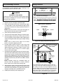
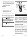
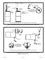
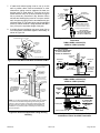
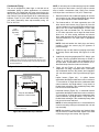
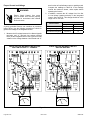
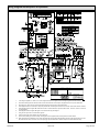
Venting Practices
* See table 2 for allowable pipe.
NOTE - Isolate piping at the point where it exits the outside wall o
r
roof in order to prevent transmission of vibration to the structure.
SCHEDULE 40
PVC - 5'
all other pipe* - 3'
Wall edistuoedisni
24” maximum
3/4” minimum
Wall Thickness Guidelines
NOTE -
ward unit a minimum of 1/4” (6mm) drop for each 12” (305mm).
Figure 18. Piping Suspension Guidelines
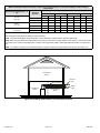
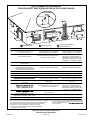
If the 95G1UHEX furnace replaces a furnace that was
commonly vented with another gas appliance, the size of
the existing vent pipe for that gas appliance must be
checked. Without the heat of the original furnace flue prod-
ucts, the existing vent pipe is probably oversized for the
single water heater or other appliance. The vent should be
checked for proper draw with the remaining appliance.
CHIMNEY
OR GAS
VENT
(Check sizing
for water
heater only)
FURNACE
WATER
HEATER
OPENINGS
(To Adjacent
Room)
REPLACING FURNACE THAT
WAS PART OF A COMMON
VENT SYSTEM
Figure 19.

508034-02 Issue 2135 Page 17 of 49
1. In areas where piping penetrates joists or interior walls,
hole must be large enough to allow clearance on all
sides of pipe through center of hole using a hanger.
2. When furnace is installed in a residence where unit
is shut down for an extended period of time, such
as a vacation home, make provisions for draining
condensate collection trap and lines.
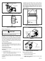
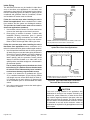
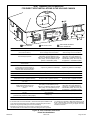
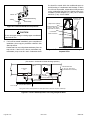
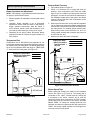
Exhaust Piping
See Figure 20, Figure 23 and Figure 24
The vent adapter must be must be attached to the exhaust
coupling on the furnace top panel. Use the provided bands.
See steps below.
1. Remove the caution sticker from vent adapter.
2. Fully insert vent adapter with both bands loosely
attached on the furnace exhaust coupling.
3. Insert PVC exhaust pipe through vent adapter. Ensure
vent pipe is fully seated into exhaust coupling.
4. Tighten both top and bottom bands to 40 in lbs. See
Figure 20.
5. Tighten top band.
Route piping to outside of structure. Continue with
installation following instructions given in piping termination
section.
Do not discharge exhaust into an existing stack or
stack that also serves another gas appliance. If vertical
discharge through an existing unused stack is required,
insert PVC pipe inside the stack until the end is even
with the top or outlet end of the metal stack.
CAUTION
The exhaust vent pipe operates under positive pressure
and must be completely sealed to prevent leakage of
combustion products into the living space.
CAUTION
Furnace
Top Band
(torque to 40in−lbs)
PVC
Exhaust Pipe
To p Panel
Bottom Band
(torque to 40in−lbs)
Vent
Adaptor
Furnace
Exhaust Coupling
Figure 20. Vent Adaptor to Exhaust Coupling
Vent Piping Guidelines
NOTE: Allied Air has approved the use of DuraVent® and
Centrotherm manufactured vent pipe and terminations as
an option to PVC. When using the PolyPro® by DuraVent
or InnoFlue® by Centrotherm venting system the vent
pipe requirements stated in the unit installation instruction
– minimum & maximum vent lengths, termination
clearances, etc. – apply and must be followed. Follow
the instructions provided with PolyPro by DuraVent and
InnoFlue by Centrotherm venting system for assembly
or if requirements are more restrictive. The PolyPro by
Duravent and InnoFlue by Centrotherm venting system
must also follow the uninsulated and unconditioned space
criteria listed in Table 14.
The 95G1UHEX can be installed as either a Non-Direct
Vent or a Direct Vent gas central furnace.
NOTE: In Non-Direct Vent installations, combustion air is
taken from indoors and ue gases are discharged outdoors.
In Direct Vent installations, combustion air is taken from
outdoors and ue gases are discharged outdoors.
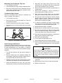
Intake and exhaust pipe sizing -- Size pipe according
to Table 10 and Table 12A through Table 12B. Count all
elbows in side and outside the home. Table 10 lists the
minimum vent pipe lengths permitted. Table 12A through
Table 12B lists the maximum pipe lengths permitted.
Regardless of the diameter of pipe used, the standard roof
and wall terminations described in section Exhaust Piping
Terminations should be used. Exhaust vent termination
pipe is sized to optimize the velocity of the exhaust gas as
it exits the termination. Refer to Table 15.

508034-02Issue 2135Page 18 of 49
In some applications which permit the use of several
dierent sizes of vent pipe, a combination vent pipe may
be used. Contact Allied Air Technical Service for assistance
in sizing vent pipe in these applications.
NOTE: The exhaust collar on all models is sized to
accommodate 2” Schedule 40 vent pipe. In horizontal
applications, any transition to exhaust pipe larger than 2”
must be made in vertical runs of the pipe. Therefore a 2”
elbow must be added before the pipe is transitioned to
any size larger than 2”. This elbow must be added to the
elbow count used to determine acceptable vent lengths.
Contact the Application Department for more information
concerning sizing of vent systems which include multiple
pipe sizes.
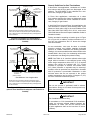
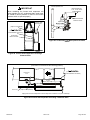
NOTE - Exhaust pipe MUST be glued to furnace exhaust fittings.
NOTE -
ward unit. A minimum of 1/4” (6mm) drop for each 12” (305mm)
of horizontal run is mandatory for drainage.
NOTE - Exhaust piping should be checked carefully to make
sure there are no sags or low spots.
Exhaust Pipe
Horizontal
Gas Furnace
12” Min.
12” Max.
Figure 21. Horizontal Installation Oset Requirements
Model Min. Vent Length*
040, 060, 080, 100
15 ft. or
5 ft. plus 2 elbows or
10 ft. plus 1 elbow
*Any approved termination may be added to the minimum
length listed.
Table 10. Minimum Vent Pipe Lengths
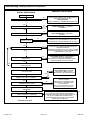
Use the following steps to correctly size vent pipe diameter.
040, 060,
080, 100 btuh
Standard or
Concentric?
See Table 11
Intake or
Exhaust?
2” or 3”
Furnace capacity?
1
Which termination?
2
Which needs most
elbows?
3
How many?
4
Desired pipe size?
5
What is the altitude?
6
Use Table 12A through
Table 13 to find max pipe
length or exhaust pipe
length. Includes all vent
pipe and elbows inside
and outside the house.
7
Figure 22.
Do not use screens or perforated metal in exhaust or
intake terminations. Doing so will cause freeze-ups and
may block the terminations.
IMPORTANT

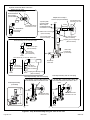
508034-02 Issue 2135 Page 19 of 49
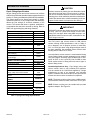
Input
Size
Vent Pipe
Dia.
(in.)
STANDARD CONCENTRIC
Flush-
Mount Kit
Wall Kit Wall Ring
Kit
Field
Fabricated
1-1/2 in. 2 in. 3 in.
2 in. 3 in. 2 in.
51W11 (US)
51W12 (CA)
22G44 (US)
430G28 (CA)
44J40 (US)
481J20 (CA) 15F74 71M80 (US)
444W92 (CA)
69M29 (US)
444W92 (CA)
60L46 (US)
444W93 (CA)
040 23YES YES 1YES 1YES 5YES 2YES
33YES YES 1YES 1YES 5YES 2YES
060 23YES YES 1YES 1YES 5YES 2YES
33YES YES 1YES 1YES 5YES 2YES
080 23YES YES YES 5YES YES YES
33YES YES YES 5YES YES YES
100 23YES YES YES 5YES YES YES
33YES YES 5YES YES YES
NOTE - Standard Terminations do not include any vent pipe or elbows external to the structure. Any vent pipe or elbows external to the structure must
be included in total vent length calculations. See vent length tables.
* Kits must be properly installed according to kit instructions.
1 Requires eld-provided outdoor 1-1/2” exhaust accelerator.
2 Concentric kits 71M80 and 44W92 include 1-1/2” outdoor accelerator, when used with 040 and 060 input models.
3 Flush mount kits 51W11 and 51W12 includes 1-1/2 in. outdoor exhaust accelerator, required when used with 040, 060 and 080 input models.
4 Termination kits 30G28, 44W92, 44W93 and 81J20 are certied to ULC S636 for use in Canada only.
5 See Table 15 for vent accelerator requirements.
Table 11. Outdoor Termination Kits

508034-02Issue 2135Page 20 of 49
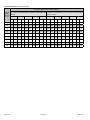
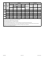
Maximum Allowable Intake or Exhaust Vent Length in Feet
Standard Termination at Elevation 0 - 4500 ft
Number of 90°
Elbows Used
2" Pipe 3" Pipe
Model Model
040 060 080 100 040 060 080 100
1 81 66 44 24 138 137 118 118
2 76 61 39 19 133 132 113 113
3 71 56 34 14 128 127 108 108
4 66 51 29
n/a
123 122 103 103
5 61 46 24 118 117 98 98
6 56 41 19 113 112 93 93
7 51 36 14 108 107 88 88
8 46 31
n/a
103 102 83 83
9 41 26 98 97 78 78
10 36 21 93 92 73 73
Standard Termination at Elevation 4501 - 7500 ft
Number of 90°
Elbows Used
2" Pipe 3" Pipe
Model Model
040 060 080 100 040 060 080 100
1 81 41 34 9 138 105 100 65
2 76 36 29
n/a
133 100 95 60
3 71 31 24 128 95 90 55
4 66 26 19 123 90 85 50
5 61 21 14 118 85 80 45
6 56 16 9 113 80 75 40
7 51 11
n/a
108 75 70 35
8 46
n/a
103 70 65 30
9 41 98 65 60 25
10 36 93 60 55 20
NOTE - Size intake and exhaust pipe length separately. Values in table are for Intake OR Exhaust, not combined total. Both Intake
and Exhaust must be same pipe size.
NOTE - Additional vent pipe and elbows used to terminate the vent pipe outside the structure must be included in the total vent length
calculation.
Table 12A.
Page is loading ...
Page is loading ...
Page is loading ...
Page is loading ...
Page is loading ...
Page is loading ...
Page is loading ...
Page is loading ...
Page is loading ...
Page is loading ...
Page is loading ...
Page is loading ...
Page is loading ...
Page is loading ...
Page is loading ...
Page is loading ...
Page is loading ...
Page is loading ...
Page is loading ...
Page is loading ...
Page is loading ...
Page is loading ...
Page is loading ...
Page is loading ...
Page is loading ...
Page is loading ...
Page is loading ...
Page is loading ...
Page is loading ...
-
 1
1
-
 2
2
-
 3
3
-
 4
4
-
 5
5
-
 6
6
-
 7
7
-
 8
8
-
 9
9
-
 10
10
-
 11
11
-
 12
12
-
 13
13
-
 14
14
-
 15
15
-
 16
16
-
 17
17
-
 18
18
-
 19
19
-
 20
20
-
 21
21
-
 22
22
-
 23
23
-
 24
24
-
 25
25
-
 26
26
-
 27
27
-
 28
28
-
 29
29
-
 30
30
-
 31
31
-
 32
32
-
 33
33
-
 34
34
-
 35
35
-
 36
36
-
 37
37
-
 38
38
-
 39
39
-
 40
40
-
 41
41
-
 42
42
-
 43
43
-
 44
44
-
 45
45
-
 46
46
-
 47
47
-
 48
48
-
 49
49


Ducane 95G1E Installation guide
- Category
- Water heaters & boilers
- Type
- Installation guide
Ask a question and I''ll find the answer in the document
Finding information in a document is now easier with AI
Related papers
Other documents
-
Lennox Integrated Control Replacement Kit 16C81 Installation guide
-
-
-
-
-
Lennox EL297DFV User manual
-
-
-
-