Pentair HYPRO 9303C-SP Original Instruction Manual
- Category
- Water pumps
- Type
- Original Instruction Manual
This manual is also suitable for

Pentair
375 5th Ave., New Brighton, MN 55112
Phone: (651)766-6300 -OR- 800-424-9776 Fax: 800-323-6496
www.hypropumps.com
EU Authorized Representative: QNET BV Hommerterweg 286
6436 AM Amstenrade, The Netherlands
KvK Zuid-Limburg 14091511
EC REP
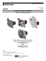
Hypro Series 9303
Form L-1547
Rev. B
Original Instruction Manual
9303C, 9303S, 9303C-SP & 9303S-SP
Cast Iron & Stainless Steel Series
Centrifugal Pumps
9303P
Polypropylene Series
Centrifugal Pumps
KEEP FOR FUTURE REFERENCE

Contents
EU Language .........................................................................................................................................................................3
Introduction.................................................................................................................................................................4
Description.....................................................................................................................................................4
Intended Uses............................................................................................................................................................4
Purpose of Manual....................................................................................................................................................4
Misuses...........................................................................................................................................................4
Pump Identication....................................................................................................................................................5
PumpTechnicalData.................................................................................................................................................5
Fluid Pumping Applications.........................................................................................................................................12
Tools................................................................................................................................................................12
Lifting, Transport, and Intermediate Storage...............................................................................................................12
Assembly and Installation........................................................................................................................................................13
Assembly.........................................................................................................................................13
Installation......................................................................................................................................13
Plumbing Diagram.....................................................................................................................................................14
Commissioning, Start-Up, Operation, Shutdown...................................................................................................................16
Information.....................................................................................................................................16
Start-Up, Operation, Shutdown................................................................................................................................16
Maintenance and Servicing..................................................................................................................................................18
Information............................................................................................................................18
Disposal.................................................................................................................18
Cleaning............................................................................................................................18
Maintenance, Routine Servicing, and Inspection.....................................................................................................18
Troubleshooting.................................................................................................................................19
Replacement Parts...................................................................................................................................................20
Declaration of Incorporation.................................................................................................................................................23
Warranty ................................................................................................................................................................... Last page
- 2 -

- 3 -
EU Languages
DO NOT attempt to install or operate your pump before reading the manual. Original copies of the manual for Hypro
pumpsareprovidedinEnglish.Tondacopyinyournativelanguage,gotowww.hypropumps.com.
Vor dem Ablesen des Handbuches versuchen Sie NICHT, Ihre Pumpe zu installieren. Originale des Handbuches fur
Hypro-PumpenwerdenaufenglischzurVerfugunggestellt.ZueineKopieinIhrerMuttersprachenden,zu
www.hypropumps.com zu gehen (German)
N’essayez pas d’installer votre pompe avant de lire le manuel. Des exemplaires originaux du manuel pour des pompes
de Hypro sont fournis en anglais. Pour trouver une copie dans votre langue maternelle pour aller a
www.hypropumps.com (French)
NON tentare di installare la vostra pompa prima di leggere il manuale. Esemplare originale del manuale per Hypro
pompe sono in inglese. Per trovare una copia nella vostra lingua andare a www.hypropumps.com (Italian)
Непытайтесьустановитьвашнасосдочтенияруководства.Оригинальныекопииэтогоруководствадлянасосы
Hyproнаанглийскомязыке.Найтикопиюнавашроднойязыкперейтикwww.hypropumps.com(Russian)
NO intente instalar su bomba antes de leer el manual. Copias originales del manual para Hypro se provee de bombas
en ingles. Para encontrar una copia en tu idioma nativo ir a www.hypropumps.com (Spanish)
NIEprobowaćinstalowaćpompyprzedjejodczytanieminstrukcji.OryginalnekopieinstrukcjiobsługipompHyprosą
dostarczanewjęzykuangielskim.Abyuzyskaćkopięwtwoimojczystymjęzykuprzejdźdowww.hypropumps.com
(Polish)
Takmayacalışmayınokumadanoncepompanınmanuel.OrijinalkopyalarınıHypropompalarıicinIngilizceolarak
sunulmuştur.Birkopyasınıbulmakicinyereldilgitwww.hypropumps.com(Turkish)
Nao tente instalar a bomba antes de ler o manual. As copias originais dos manuais para Hypro bombas sao
fornecidos em Ingles. Para encontrar uma copia em sua lingua nativa ir para www.hypropumps.com (Portuguese)
VERGEETNIETuwpompvoorhetlezenvanhethandboek.ExemplarenvandehandleidingvoorHypropompenzijn
beschikbaarinhetEngels.Opzoeknaareenexemplaarinuweigentaalganaarwww.hypropumps.com(Dutch)

Introduction
Description
Hyprocentrifugalpumpsaredesignedforcreatingandboostingpressureinuidcircuits.Thepumpoperatesbytaking
inuidfromtheinletportafterwhichitisslungbytheimpellerandexpelledthroughtheoutletport.Constructionfeatures
include housings, impellers and seals which come in a variety of materials in order to be resistant to a range of chemicals.
Standardmodelsofcentrifugalpumpsrotateclockwise,whenlookingattheshaftendofthepump.
Intended Uses
Hyprocentrifugalpumpsareintendedforcreatingorboostingdynamicpressureinapproveduids.Hyprocentrifugal
pumps should never be used to pump liquids above 140°F (60°C), or below 34°F (1°C). For pumps equipped with
hydraulicmotors,thepumpshouldnotberunifthehydraulicoiltemperatureexceeds135°F(57°C).Anyusesoutside
ofthosespeciedinthismanualareconsideredmisusesandareprohibited.ContactHyprotechnicalservicewithany
questionsregardingspecicacceptableuses.
Purpose of Manual
This manual provides instructions and requirements that must be met when installing, using and maintaining the
product(s)identiedonthecover.
If the product is sold, the seller must pass this manual onto the new owner.
The following special attention notices are used to notify and advise the user of this product of procedures that may be
dangerous to the user or result in damage to the product.
ATTENTION
Attention is used to notify of installation, operation, or maintenance information that is important but not safety related.
Thissymbolisusedtodenotethepresenceofanelectricalhazardthatwillresultinpersonalinjury,deathorproperty
damage.
Thissymbolisusedtodenotethepresenceofahazardthatwillresultinpersonalinjury,deathorpropertydamage.
California Proposition 65 Warning --Thisproductandrelatedaccessoriescontainchemicalsknowntothe
State of California to cause cancer, birth defects or other reproductive harm.
Misuses
Hyprocentrifugalpumpsaredesignedtooperateeffectivelywithinthespeciedspeed,pressureandenvironmental
ranges.Goingoutsideoftheserangeswillvoidthewarrantyandcouldcausedamagetoproperty,seriousinjury,ordeath.
• DO NOTrunthepumpfasterthanthemaximumspeciedspeed.
• DO NOTrunthepumphigherthanthemaximumspeciedpressure.
• DO NOT run pumps when the liquid has exceeded the maximum or minimum temperature limit (see Intended Uses).
• DO NOT pump non-approved liquids.
• DO NOT pump water or other liquids for human consumption.
• DO NOToperateanyHypropumpundertheinuenceofdrugsoralcohol.
• DO NOT run the pump dry.
• DO NOT run the pump with a higher than recommended voltage.
• DO NOTrunthepumphydraulicmotorhigherthanthespeciedRPM,pressureorow.
- 4 -

- 5 -
Pump Identication
Hypro uses serialized labeling to enable users to precisely identify the pump’s manufacturing date.
Serial Number:
First and second digits: year (14 = 2014)
Third through fth digits: consecutive day of the year the pump was manufactured.
Sixth through tenth digits: unique pump serial number.
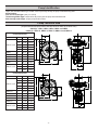
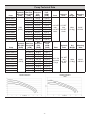
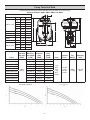
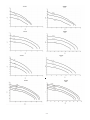
Pump Technical Data
(Allspecicationsandperformancedataarebasedonwaterasacarrieruid.)
9303C(S) - HM1C, HM2C, HM3C, HM4C and HM5C
9303C(S) - HM1C-U, HM2C-U, HM3C-U, HM4C-U and HM5C-U
Pump Dimensions
Dim. Inch mm
HM1,2,3,4,5
A8.37 212.6
B 7.78 197.6
C 4.19 106.4
D 3.81 96.8
E 3.06 77.7
HM1C F 11.07 281.2
HM2C F 10.82 274.8
HM3C F 11.57 293.9
HM4C F 10.92 277.4
HM5C F 11.19 284.2
HM1,2,3,4,5
G 4.63 117.6
H5.25 133.4
I 2.63 66.8
Pump Dimensions
Dim. Inch mm
HM1,2,3,4,5
A 8.43 214.1
B8.19 208.0
C 4.60 116.8
D 3.81 96.8
E 3.06 77.7
HM1C-U F 11.86 301.2
HM2C-U F 11.98 304.3
HM3C-U F 12.36 313.9
HM4C-U F 11.98 304.3
HM5C-U F 12.29 312.2
HM1,2,3,4,5
G5.42 137.7
H5.25 133.4
I 2.63 66.8

Pump Technical Data
Pump
Hydraulic
Max (PSI)
[BAR]
Max Flow
Rate (GPM)
[LPM]
Max
Pressure
(PSI)
[BAR]
Max Hyd.
Flow
(GPM)
[LPM] Ports
Hydraulic
Ports
Dry
Weight
Mounting
Bolts
9303C-HM1C
3000
[206.8]
114[431.5] 130 [9] 13 [49.2]
1-1/2" NPT
Inlet
1-1/4” NPT
Outlet
1/2” NPT
Inlet
3/4” NPT
Outlet
26lbs
[11.8kg]
2X 3/8"
OR M10
9303C-HM2C 97[367.2] 95[6.5] 6[22.7]
9303C-HM3C 125[473.1] 98 [6.8] 24 [90.8]
9303C-HM4C 115[435.3] 93 [6.4] 7[26.5]
9303C-HM5C 147[556.5] 145[10] 16 [60.6]
9303S-HM1C 114[431.5] 130 [9] 13 [49.2]
9303S-HM2C 97[367.2] 95[6.5] 6[22.7]
9303S-HM3C 125[473.1] 98 [6.8] 24 [90.8]
9303S-HM4C 115[435.3] 93 [6.4] 7[26.5]
9303S-HM5C 147[556.5] 145[10] 16 [60.6]
Pump
Hydraulic
Max (PSI)
[BAR]
Max Flow
Rate (GPM)
[LPM]
Max
Pressure
(PSI)
[BAR]
Max Hyd.
Flow
(GPM)
[LPM] Ports
Hydraulic
Ports
Dry
Weight
Mounting
Bolts
9303C-HM1C-U
3000
[206.8]
114[431.5] 130 [9] 13 [49.2]
220 X 200
Universal
Flange
1/2” NPT
Inlet
3/4” NPT
Outlet
26lbs
[11.8kg]
2X 3/8"
OR M10
9303C-HM2C-U 97[367.2] 95[6.5] 6[22.7]
9303C-HM3C-U 125[473.1] 98 [6.8] 24 [90.8]
9303C-HM4C-U 115[435.3] 93 [6.4] 7[26.5]
9303C-HM5C-U 147[556.5] 145[10] 16 [60.6]
9303S-HM1C-U 114[431.5] 130 [9] 13 [49.2]
9303S-HM2C-U 97[367.2] 95[6.5] 6[22.7]
9303S-HM3C-U 125[473.1] 98 [6.8] 24 [90.8]
9303S-HM4C-U 115[435.3] 93 [6.4] 7[26.5]
9303S-HM5C-U 147[556.5] 145[10] 16 [60.6]
- 6 -

- 7 -

- 8 -
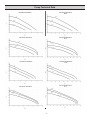
Pump Technical Data
(Allspecicationsandperformancedataarebasedonwaterasacarrieruid.)
9303C(S)-SP HM1C, HM2C, HM3C, HM4C and HM5C
Pump Dimensions
Dim. Inch mm
HM1,2,3,4,5
A 11.69 296.8
B 8.07 205.0
C 4.48 113.8
D 9.31 263.5
E 0.88 22.2
HM1C F 12.41 315.2
HM2C F 12.17 309.1
HM3C F 12.92 328.2
HM4C F 12.22 310.4
HM5C F12.54 318.5
HM1,2,3,4,5
G5.98 151.8
H5.25 133.4
I 2.63 66.7
Pump
Hydraulic
Max (PSI)
[BAR]
Max Flow
Rate (GPM)
[LPM]
Max
Pressure
(PSI)
[BAR]
Max Hyd.
Flow
(GPM)
[LPM] Ports
Hydraulic
Ports
Dry
Weight
Mounting
Bolts
9303C-HM1C-SP
3000
[206.8]
122 [461.8] 130 [9] 13 [49.2]
1-1/2"
NPT
Inlet
1-1/4”
NPT
Outlet
1/2” NPT
Inlet
3/4” NPT
Outlet
38lbs
[17.3kg]
3/8" OR
M10
9303C-HM2C-SP 104[393.7] 80[5.5] 6[22.7]
9303C-HM3C-SP 120[454.2] 95[6.5] 24 [90.8]
9303C-HM4C-SP 99[374.8] 97[6.7] 7[26.5]
9303C-HM5C-SP 140[530] 140[9.7] 16 [60.6]
9303S-HM1C-SP 114[431.5] 130 [9] 13 [49.2]
9303S-HM2C-SP 97[367.2] 95[6.5] 6[22.7]
9303S-HM3C-SP 125[473.1] 98 [6.8] 24 [90.8]
9303S-HM4C-SP 115[435.3] 93 [6.4] 7[26.5]
9303S-HM5C-SP 147[556.5] 145[10] 16 [60.6]

- 9 -
Pump Technical Data

Pump Identication
Hypro uses serialized labeling to enable users to precisely identify the pump’s manufacturing date.
Serial Number:
First and second digits: year (14 = 2014)
Third through fth digits: consecutive day of the year the pump was manufactured.
Sixth through tenth digits: unique pump serial number.
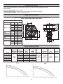
Pump Technical Data
(Allspecicationsandperformancedataarebasedonwaterasacarrieruid.)
9303P - HM1C, HM2C, HM3C, HM4C, HM5C
Pump Dimensions
Dim. Inch mm
HM1,2,3,4,5
A8.75 222.2
B8.33 211.7
C 4.12 104.6
D 4.44 112.7
E 3.06 77.7
HM1 F 10.97 278.6
HM2 F 10.72 272.3
HM3 F 10.47 291.3
HM4 F 10.77 273.6
HM5 F 10.10 256.5
HM1,2,3,4,5
G4.56 115.9
H 3.00 76.2
I1.50 38.1
Pump Technical Data
Pump
Hydraulic
Max (PSI)
[BAR]
Max Flow
Rate (GPM)
[LPM]
Max
Pressure
(PSI)
[BAR]
Max Hyd.
Flow
(GPM)
[LPM] Ports
Hydraulic
Ports
Dry
Weight
Mounting
Bolts
9303P-HM1C
3000
[206.8]
110 [416.4] 130 [8.9] 13 [49.2]
1-1/2” NPT
Inlet
1-1/4” NPT
Outlet
1/2” NPT
Inlet
3/4” NPT
Outlet
21lbs
[935kg]
4X 3/8"
OR M10
9303P-HM2C 82 [310.4] 95[6.5] 6[22.7]
9303P-HM3C 110 [416.4] 93 [9.4] 24 [90.8]
9303P-HM4C 82 [310.4] 84[5.8] 7[26.5]
9303P-HM5C 113[427.7] 120 [8.2] 16[60.5]
- 10 -

- 11 -

- 12 -
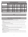
Fluid Pumping Applications
Application
Pump Materials Compatibility
Impeller Pump Housing Seal
Nylon Polypropylene GTX Stainless Polypropylene Cast
Iron Ceramic Silicon
Carbide
Weed Control Chemicals X X X X X X X X
Insect Control X X X X X X X X
BrushControl X X X X X X X X
Pest Control Chemicals
and Fumigants X X X X X X X X
Liquid Fertilizers X X X X X X X
Powdered Fertilizers X X X X X X X X
Fluid Transfer X X X X X X X X
Acids X X X X
Table 1
Flammable liquids, sewage, and potable water should never be pumped through a Hypro pump.
Tools
The Hypro centrifugal pumps and mounting assemblies are designed with Imperial (inch) bolts, however, there are many
metric(mm)sizeswhichwillworkwiththesemounts.Inmostcases,anadjustablespannerwrenchcanalsobeused.
Lifting, Transport, and Intermediate Storage
Packaging Descriptions and Unpacking Instructions
• Hypro centrifugal pumps are shipped in cardboard boxes for safe transporting.
• When pumps are shipped in large quantities, they may be put on a pallet to allow for easy storage, lifting and
handling.
• Beforeliftinganypumporpallet,determinetheweightoftheitembylookingattheattachedpackingslipstoestablish
what lifting equipment should be used.
• Beforeinstallingthepump,determineifallthecomponentsarepresentandundamaged.Ifthepumpismissing
components, contact customer service immediately.
• Oncethepumpisunpacked,disposeofthepackaginginamannercompliantwithlocalandnationalregulations.
Lifting Instructions
• BeforeattemptingtoliftaHypropump,ensurethatthesurroundingworkingareaisfreeofhazardswhichcouldcause
injuryordamagetoproperty.
• Duringliftingoperations,anypersonnelnotinvolvedintheliftshouldnotentertheworkingarea.
• Ifliftinghooks,ropeorchainsarebeingusedforalift,theymustbefreeofdamageandberatedtocarry150%ofthe
weight of the load to be lifted.
• Always wear steel-toed shoes and cut-resistant gloves when attempting to lift.
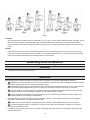
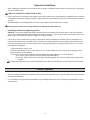
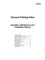
• Whenliftingandcarrying,alwayskeepthepumpclosetoyourbody.(SeeFigure1)
• Whenstartingthelift,bendyourkneesandkeepyourbackstraight.(SeeFigure1)Tighteningthestomachmuscles
willhelpkeepyourbackstraight.
• Duringthelift,useyourlegstodothework.Neveruseyourbackandmakesureyourlegsareatleastshoulder-width
apart. (See Figure 1)

- 13 -
Figure 1
Transport
• All Hypro pumps are capable of being transported by air, sea, rail or motor vehicle. When the pump is shipped, ensure
that the pump is moved in accordance with local and national laws and is properly secured to prevent unwanted
movementwhichcouldcausedamagetopersonorproperty.Priortoshipping,alluidsshouldberemovedfromthe
pump.
Storage
• New pumps in their boxes can be stored several years as long as the port plugs are not removed. Once the plugs
have been removed, if the pump is not to be used for an extended period of time (i.e. more than 30 days), the pump
must be winterized as described in the Cleaning section of this manual.
Assembly and Installation
Assembly
• This pump comes completely assembled.
Installation
BeforeattemptingtoinstallyourHyprocentrifugalpumpitisimperativetoreadandunderstandthefollowing:
• InstallationofaHypropumpshouldonlybeperformedbyatechnicianhavingtheknowledgeandskillsnecessary
toinstallthepumpwithouttheriskofpropertydamageorinjury.
• When handling Hypro pumps, one should wear steel-toed shoes and protective gloves in order to protect the feet
in the event the pump is dropped and protect the hands from any sharp surfaces on the pump or chemicals.
• Pumping systems must be installed in accordance with Hypro installation instructions. Failure to do so will void
yourwarrantyandcouldcausedamagetoproperty,seriouspersonalinjury,ordeath
• Itistheinstaller’sresponsibilitytoconductelectricaltestsinaccordancewithEN60204-1:2006/A1:2009,orits
supersedingstandard,onnishedpumpassemblies.
• All connections to electrical components must be number, symbol, or color-coded generally as recommended by
EN60204-1:2006/A1:2009,oritssupersedingstandard.
• Installers must provide hydraulic components that are capable of withstanding maximum source pressure.
• Theworkingpressuremustbecontrolledbyapressurereliefvalvethatisadjustedtooperateatamaximum
pressure of the hydraulic motor.
• If a rigid plumbing system is to be used on a Hypro centrifugal pump, the system must be properly aligned with the
inlet and outlet ports.

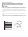
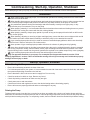
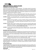
Ref.
No. Description
1TankLid
2 Vent Line
3Jet Agitator
4Shut-offBallValves
5Centrifugal Pump
6 Spray Control Console
7Centrifugal Pump Control
8ManifoldBoomValve
9 Flowmeter
10 JetTurretNozzleBody
- 14 -
• Theworkingpressureinthehydraulicssystemmustbecontrolledbyapressurereliefvalvethatisadjustedto
operateat10%ofthemaximumsystempressure.
• Wheninstalling,adjustingorremovingaHyprocentrifugalpump,ensurethattherearenoobjectswhichcanfall
ontheinstallerandmakecertainthatallmachinerytowhichthepumpistobeattachedisturnedoff.
• Pumps must be installed in a location where they are accessible for any necessary maintenance.
• Whenhydraulicpowerisused,thesystemshouldcontainaquickdisconnectcouplingthatcanbedisconnected
to isolate the pump.
Standard Mounting
• Inordertopreventinjuryordamagetoproperty,allHypropumpsshouldbeproperlymountedtoasolidbasewhere
thereisnodangerofthepumpfallingorbreakingloose.AllHypropumpscomewithmountingholeswhichallow
bolts to be put into the pump so it can be secured to a sturdy base. When mounting your Hypro centrifugal pump, be
sure to use bolts and nuts which are compatible with any chemicals that may come into contact with them as well as
choosing the correct grade of bolt based on the pump weight and any expected loads. Pumps should be mounted
as close to the liquid source as possible. Non self-priming pumps must be mounted below the liquid level to function
properly.
Pump Plumbing
• To achieve maximum pump performance, the outlet port on the pump should be pointing straight up, and pump
inlet and outlet lines should be at least the same size as their respective port. Pump plumbing must be capable of
withstanding the maximum suction, and pressure, generated by the pump and should have as few restrictions as
possible.
• For best priming results, the upper most vent plug can be removed and a vent line can be installed. This line prevents
airlockandallowsthepumptoprimeitselfbybleedingofftrappedair.

Hydraulic Installation
• Wheninstallingthehydraulicmotorintothetractororsprayer’shydraulicsystem,makesurethatnodirtorliquidgets
into the hydraulic motor.
KEEP ALL HYDRAULIC CONNECTIONS CLEAN.
• Ensure return line is connected to low pressure return port on the tractor recommended for hydraulic motors, the ports
areidentiedonthemotorcasting.Hydraulicsupplylinesshouldbeatleastthesamesizeasthehydraulicmotorport
or larger.
• Standardmodelscomeequippedwithcheckvalveportadaptersthatshouldnotberemoved.
Hooking up the motor in the wrong direction will damage the hydraulic seal.
• Installing and Removing Metering Orice
Attention: ForpumpsequippedwithHM2andHM4motors,themeteringoriceshouldnotbeusedifthehydraulic
systemisaload-sensing(ow-compensated)closedcentersystem,orifitisanopencentersystemwithamaximum
owof8gpm[30.28lpm]forHM2Cor10gpm[37.85lpm]forHM4C.
• Correctoricesizeisdeterminedbysystemperformance.Startbyinstallingthesmallestoriceintheadaptercon-
nectedtothepressureport.Oncetheoriceisinstalled,testsystemperformanceandifsystemperformanceislow,
installthenextlargestorice.Continuethisprocessuntilpumpperformancereachesthedesiredlevel,ornoorices
are installed in the adapter.
1) Ensure hydraulic system is off.
2)Removetheadapterfromthemotorusinga1-1/16’’wrench.MakesuretheO-ringisonthemeteringorice
before installing into port adapter.
3)Theoriceisremovedorinstalledintheportadapterbytappingeitherinoroutoftheadapter.
a)Toremove,taptheoriceoutfromthesmallendoftheadapter.
b)Toinstall,taptheoriceinfromthelargeendoftheadapter.Theoriceisseatedwhenasnapsound
is heard.
ForHM2andHM4motors,thepressuredifferentialacrossthemotorshouldneverexceed2500PSI[172.4BAR].
Control Systems
• All pump systems with electric or hydraulic power sources are required to have a control system which meets all local
and national standards.
• For more detail on a typical system installation, see preceding subsections of the “Assembly and Installation” section
of this manual.
- 15 -

- 16 -
Commissioning, Start-Up, Operation, Shutdown
Beforeattemptingtostartyourpump,thefollowingmustbeunderstoodandfollowedtoensuresafeoperation.
Information
• When running Hypro centrifugal pumps, it is essential that operators use hearing protection as the sound levels
can reach levels of 80 decibels.
• When handling Hypro pumps, one should wear steel-toed shoes and protective gloves in order to protect the feet
in the event the pump is dropped and protect the hands from any sharp surfaces on the pump or chemicals.
• OnlyauthorizedoperatorshavingtheknowledgeandskillnecessarytosafelyuseaHypropump,orany
equipment the pump is connected to, may run the pump.
• Whensprayingmanually,itisrecommendedthatchemical-resistantfacemasksandclothingbeworntoprevent
anychemicalsfromcomingintocontactwiththeskinorbeinginhaled.
• When spraying manually, always spray upwind of yourself as long as the sprayed chemical will not drift into the
vicinity of other people.
• Wheninstalling,adjustingorremovingaHyprocentrifugalpump,ensurethattherearenoobjectswhichcanfall
ontheinstallerandmakecertainthatallmachinerytowhichthepumpistobeattachedisturnedoff.
• Hypro centrifugal pumps should only be used on tractors or tow-behind spray platforms which have electrically
conductivetiresinordertoreducetheriskofelectrocution.
• NeveroperateaHyprocentrifugalpumpoutsidewhilethereisachanceofgettingstruckbylightning.
• Never leave electrical wires or plumbing components where they can be a tripping hazard or become entangled
inamovingcomponent.Ideally,electricalcables,hoses,pipesandttingsshouldberoutedoverhead.Intheevent
electrical wiring must be routed over the ground, operators are required to use rubber ramps if they cross a gangway.
• Hypro centrifugal pumps should not be used if the ambient light is below 200lux.
Only use approved chemicals in your pump. For a complete list of approved chemicals, see the “Fluid
Pumping Applications” section. Failure to follow this warning will void your warranty and could lead to property
damage, serious injury or death.
Start-up, Operation, Shutdown
Before Starting the Pump
• Ensure all unnecessary personnel are clear of the area.
• Forinitialsetupandtestofyoursystem,itisrecommendedtostartwithcleanwaterinsteadofchemicals,andconrm
thesystemandplumbingconnectionsareleakfree.
• Ensurethatthereisuidinthesourcetankorsupplyline.Donotrundry.
• Checklinestrainerfordebrisorclogs.Removeanyfound.
• Checkallplumbingconnectionstomakesuretheyaretight.
• Checkpowersourceandconnections.
• Checkthatallvalvesandregulatorsaresettothedesiredsettingandarefunctioningproperly.
• Ensure all hoses are properly positioned and are not damaged in any way.
Priming the Pump
Tohelpprimethepump,keeptheinletorsuctionlineasshortaspossiblewithaminimumofbends,elbowsandkinks.
Makesureallconnectionsaretightanddonotleakair.Nonself-primingpumpsmusthavetheinletlineandpumpooded
withliquidbeforestartingthepump.Forself-primingmodels,thefrontchambershouldbelledwithliquidbeforestarting.

- 17 -
Starting, Operation and Shutdown of the Pump (Hydraulic)
Open Center Systems - All Models
Adjusting Centrifugal Pump Output
ATTENTION HM1C,HM3C&HM5Cmotorshavebypassscrewfullyclosedfromthefactory.HM2C&HM4Cmotorshave
bypass screw set at 1-1/2 turns from fully closed from the factory.
1. Openthebypassadjustmentscrew2-1/2turnsfromfullyclosedandsecureitinplacewiththebypassjamnut.
2. Start the tractor. Leave the directional valve in the neutral position and allow hydraulic oil to circulate for approximately
10to15minutesoruntiladequatelywarmed.
3. Prime the centrifugal pump with all valves open. (See Priming the Pump.)
4. Refertosprayermanufacturer’smanualtosetsprayingpressureandow.Tochangetheoworpressuregenerated
bythepump,turnthebypassscrewonthehydraulicmotor.Besuretosecurethebypassjamnutafterany
adjustment.
5. To shutdown, return directional valve to neutral and allow the pump to come to a gradual stop.
When bypassing hydraulic oil, a large amount of heat can be generated which will damage the tractor’s hydraulic
system.Besuretomonitortheoiltempwhenbypassinghydraulicoil.
Closed Center (Pressure-Compensated)
Adjusting Centrifugal Pump Output
1. Openthebypassadjustingscrewinthehydraulicmotorthree(3)turnsandsecureitinplacewiththebypassjamnut.
2. Startthetractorandallowhydraulicoiltocirculateforapproximately10to15minutesoruntiladequatelywarmed
3. Closeandlockdownthebypassadjustingscrewinthehydraulicmotor.
4. Prime the centrifugal pump with all valves open. (See Priming the Pump.)
5. Refertosprayermanufacturer’smanualtosetsprayingpressureandow.Tochangetheoworpressuregenerated
bythepump,slowlyadjusttractor’sowcontrolvalve.
6. Toshutdown,thepumpmovetheselectorforthetractorspoolvalvetotheoatpositionandallowthepumptocome
to a gradual stop.
If the pump is not brought to a gradual stop, the sudden change in hydraulic pressure and pump RPM could cause
damage to the pump’s drive system.
Closed Center (Load-Sensing) Systems
Adjusting Centrifugal Pump Output
1. Closeandlockdownthebypassadjustingscrewinthehydraulicmotor.
2. Setthetractorhydraulicowcontrolvalveforminimumhydraulicoilowtotheremoteoutlet(Tortoiseposition).
3. Startthetractorandallowthehydraulicoiltocirculateforapproximately10to15minutesoruntiladequatelywarmed.
4. Prime the centrifugal pump with all valves open. (See Priming the Pump.)
5. Refertosprayermanufacturer’smanualtosetsprayingpressureandow.Tochangetheoworpressuregenerated
bythepump,slowlyadjusttractor’sowcontrolvalve.
6. Toshutdownthepump,movetheselectorforthetractorspoolvalvetotheoatpositionandallowthepumptocome
to a gradual stop.
If the pump is not brought to a gradual stop, the sudden change in hydraulic pressure and pump RPM could cause
damage to the pump’s drive system.

- 18 -
Maintenance and Servicing
Information
• All maintenance should be done when machinery is stationary and has been isolated from its energy sources. It
is dangerous to perform maintenance while machinery is still connected to its power source. Machinery should be
isolated from its electrical, hydraulic or gas engine power source.
• BesuretoreleaseallpressurefromthesystembeforeperforminganysortofmaintenanceonaHypropump.
• DO NOT perform service or maintenance to the pump, or attached components, until the pump unit is below
109°F(43°C).
• The lubrication of this pump unit has been done at the factory prior to shipping.
• When handling Hypro pumps, one should wear steel-toed shoes and protective gloves in order to protect the feet
in the event the pump is dropped and protect the hands from any sharp surfaces on the pump or chemicals. If the
pump is being repaired while the pump is in service, eye protection should also be worn.
Any hazardous liquids should be disposed of in a manner which complies with local and national regulations. Never dump
uidsontotheground.
Disposal
WhendisposingofaHypropump,besuretoremovealluidsfromthepumpbeforescrapping.Theseuidsshouldbe
disposedofinamannerwhichcomplieswithlocalandnationalregulations.Neverdumpuidsontotheground.Oncethe
pumpisfreeofalluids,itmaybescrappedinaccordancewithlocalandnationallaws.
Cleaning
Yourpumpwilllastlongerandgivebestperformancewhenproperlytakencareof.Properpumpcaredependsonthe
liquidbeingpumpedandwhenthepumpwillbeusedagain.Aftereachuse,ushpumpwithaneutralizingsolutionforthe
liquidjustpumped.Followwithacleanwaterrinse.Thisisespeciallyimportantforcorrosivechemicals.Itisgoodpractice
to clean the pump after each use to prevent deposits from forming and damaging the pump. For infrequent use and before
long periods of storage, drain pump thoroughly. Open any drain plugs, remove suction hose from liquid, and blow pump
drywithair.Anantifreeze/rustinhibitorshouldbeinjectedintothepumpbeforebothportsarepluggedandthepumpis
stored.Plugallportstokeepoutairuntilpumpisusedagain.
Maintenance, Routine Servicing, and Inspection
PREVENTATIVE MAINTENANCE CHECKLIST
Check Daily Weekly
WaterLeaks X
Plumbing X
• Eachsystem’smaintenancecyclewillbeexclusive.Ifsystemperformancedecreases,checkimmediately.
• Dutycycle,temperature,quality,typeofuidbeingpumped,andinletfeedconditionsallaffectthelifeofsprayboom
assemblies and service cycle.

- 19 -
Troubleshooting
Beforeattemptingtoserviceyourpump,besurethatitisdisconnectedfromallenergysources.
Symptom Probable Cause(s) Corrective Action
Pump does not prime Leakinsuctionline Checkhoseandttingsforleaksand
correct
Obstruction in suction line Inspect hose for obstructions and
remove
Suctionhosestucktotank Cut a notch or “V” in end of suction
hose
Clogged strainer Checkstrainerandcleanregularly
Low discharge Pump rotates incorrectly Correct rotation of pump
Blockedsuctionhose Inspect suction hose and repair as
necessary
Pump worn Repair pump
Undersized suction line See Installation
Pump will not turn Impeller plugged Inspect and clear obstruction
Hydraulic system overheating Hydraulicbypassneedsadjustment See Installation
Insufcienthydraulichosesize See Installation
Table 2

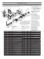
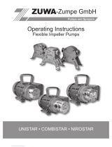
Replacement Parts
The following drawings show the pumps and their replacement parts. Only genuine replacement parts should be used.
Failure to follow this warning can result in damage to property, serious injury or death. If the pump malfunctions or
isdefective,itshouldbesentbacktoHyproforservice.
Ref. No. Qty. Req’d. Part No. Description
1 4 2406-0007 Drain/Vent Plug (9303C)
1 4 2406-0016 Drain/Vent Plug (9303S)
1A 4 2406-0007 Drain/Vent Plug
1B 4 2406-0001 Vent Plug
2 1 0150-9000C Pump Casing (Model 9303C)
2 1 0150-9000S Pump Casing (Model 9303S)
2A 1 0153-9000C Pump Casing (Universal Flange Model C-U)
2A 1 0153-9000S Pump Casing (Universal Flange Model S-U)
2B 10150-9070CM Pump Casing
3 1 3430-0825 Impeller Nut (9303C)
3 1 3430-0825 Impeller Nut (9303S)
4 1 0401-9100P Impeller (Nylon Std. 9303C)
4 1 0402-9100P Impeller (Polypropylene Optional) (Std 9303S)
511720-0083 O-ring
6 1 1700-0100 Gasket
71 2120-0009 Mechanical Seal (Viton/Ceramic) (Std 9303C)
713430-0589 Mechanical Seal (Silicon Carbide) (Std 9303S)
8 1 0750-9300C Mounting Flange (9303C)
8 1 0756-9300S Mounting Flange (9303S)
9 4 2210-0020 Hex Head Cap Screw (9303C)
9 4 2210-0125 Hex Head Cap Screw (9303S)
10 1 1410-0056 Slinger Ring
11 1 1810-0014 Snap Ring
12 1 1820-0013 Retaining Ring
13 1 2000-0010 BallBearing
14 1 1410-0131 Cartridge, Front
15 21720-0268 O-ring
16 1 3430-0748 Lip Seal
17 1 1410-0130 Seal Spacer
18 1 2029-0014 ThrustBearingAssembly
19 1 3430-0850 Shaft (HM2C/HM4C)
19 1 3430-0852 Shaft(HM1C/HM5C)
19 1 3430-0855 Shaft (HM3C)
20 1 0150-2500C MotorBody(includesneedlebearing)
21 4 2210-0005 Hex Head Cap Screw
22 2 1720-0110 O-ring
Ref. No. Qty. Req’d. Part No. Description
23 1 1600-0045 Dowel Pin (HM2C / HM4C)
23 1 1600-0044 DowelPin(HM1C/HM5C)
23 1 1600-0052 Dowel Pin (HM3C)
24 1 1600-0042 Dowel Pin (HM2C / HM4C)
24 1 1600-0037 DowelPin(HM1C/HM5C)
24 1 1600-0068 Dowel Pin (HM3C)
25 1 3900-0022 Gerotor (HM1C)
25 1 3900-0023 Gerotor (HM2C)
25 1 3900-0024 Gerotor (HM3C)
25 13900-0025 Gerotor (HM4C)
25 1 3900-0048 Gerotor(HM5C)
26 1 0701-2500C1 Gerotor Housing (HM2C Models) 1/4” wide
26 1 0700-2500C1 Gerotor Housing (HM1C Models) 1/2” wide
26 1 0703-2500C1 GerotorHousing(HM4CModels)5/16”wide
26 1 0702-2500C1 Gerotor Housing (HM3C Models) 1” wide
26 1 0704-2500C1 GerotorHousing(HM5CModels)5/8”wide
27 10254-2500C2 Motor End Plate (includes needle bearing)
28 4 2270-0039 Washer
29 4 2220-0045 Cap Screw (HM2C / HM4C Models)
29 4 2220-0021 Cap Screw (HM1C Models)
29 4 2220-0044 Cap Screw (HM3C Models)
29 4 2220-0032 CapScrew(HM5CModels)
30 1 1720-0108 O-ring
31 1 3360-0021A Pressure Port Adapter (includes o-ring)
32 1 1720-0262 O-ring
33 1 3320-0051A TankPortAdapter(includeso-ring)
34 1 3220-0029 BypassAdjustingScrew
35 11700-0047 Gasket
36 1 2270-0027 Washer
37 12250-0038 LockNut
38 1 1610-0032 Roll Pin (HM2C / HM4C)
38 1 1610-0031 RollPin(HM1C/HM5C)
38 1 1610-0055 Roll Pin (HM3C)
39 1 1810-0026 Snap Ring
40 1 1610-0012 Woodruff Key (9303C)
40 1 04432 Woodruff Key (9303S)
9303C(S)-HM1C, 2, 3, 4,
5 & -U and 9303C(S)-SP-
HM1, 2, 3, 4, 5
Silicon Carbide Seal Kit
No. 3430-0589
Contains:
Mechanicalseal(Ref.7)ando-ring
(Ref.5).
Repair Parts Kit No. 3430-0332
Contains:
Onemechanicalseal(Ref.7),one
o-ring(Ref.5)andonerubber
gasket(Ref.6).
NOTE:Whenorderingparts,giveQUAN-
TITY,PARTNUMBER,DESCRIPTION,
andCOMPLETEMODELNUMBER.
Reference numbers are used ONLY to
identify parts in the drawing and are NOT
to be used as order numbers.
Adapter Kit No. 3430-0187 (HM2
and HM4 Modes Only) Contains
oneeach:
No.3373-0020(Size#1)
No.3373-0021(Size#2)
No.3373-0022(Size#3)
No.1720-0108AdapterO-ringand
No.1720-0105OriceO-ring
SP Chamber Kit No. 3430-0480SP
Contains:Onechamberwithwear
ring.(Ref.2)oneo-ring(Ref.5),
one drain vent plug (Ref. 1) and
one vent plug (Ref. 1A).
Parts Kit No. 3430-0748
Contains:Oneeachballbearing
(Ref. 13), motor shaft seal (Ref.
16),threadsealgasket(Ref.35),
twocartridgeo-rings(Ref.15),and
washer (Ref 36); two each motor
housing o-rings (Ref. 22), and port
adapter o-rings (Ref. 30 & 32).
Hydraulic Motor Part Nos.
2500-0081C(HM1CModels)
2500-0082C(HM2CModels)
2500-0083C(HM3CModels)
2500-0084C(HM4CModels)
2500-0085C(HM5CModels)
- 20 -
Page is loading ...
Page is loading ...
Page is loading ...
Page is loading ...
-
 1
1
-
 2
2
-
 3
3
-
 4
4
-
 5
5
-
 6
6
-
 7
7
-
 8
8
-
 9
9
-
 10
10
-
 11
11
-
 12
12
-
 13
13
-
 14
14
-
 15
15
-
 16
16
-
 17
17
-
 18
18
-
 19
19
-
 20
20
-
 21
21
-
 22
22
-
 23
23
-
 24
24


Pentair HYPRO 9303C-SP Original Instruction Manual
- Category
- Water pumps
- Type
- Original Instruction Manual
- This manual is also suitable for
Ask a question and I''ll find the answer in the document
Finding information in a document is now easier with AI
Related papers
-
Hypro HYPRO 9303S Owner's manual
-
-
Pentair 1532C Self Priming Cast Iron Centrifugal Pumps Owner's manual
-
-
-
-
-
Other documents
-
-
-
Hypro 9302 & 9303 Series Cast Iron Stainless Steel Series Centrifugal Pumps Owner's manual
-
HYTECON 201001 User manual
-
 Brave BRP200TP2 Owner's manual
-
 Val-Matic Vacuum Priming Air Valve Operating instructions
-
 Shurflo 2088-343-435 Owner's manual
-
-
-
 Zuwa NIROSTAR 2000-B Operating Instructions Manual


