Page is loading ...

Page 1 of 2
5 5000 Series Pumps
SHURflo offers various pumps models for different applications. The information outlined by this manual is general, and not specific
to all 5000 series pumps. Contact SHURFLO or your local distributor for specific application information and pump selection.
SHURFLO always recommends professional installation and service of pumps and accessories.
CAUTION "Intermittent Duty" is defined as: operated and/or frequently started within a period of time that would NOT cause the motor to reach
its maximum thermal limits. Once the maximum thermal limit is obtained, the motor must be allowed to return to ambient temperature before
resuming operation.
CAUTION DO NOT use to pump flammable liquids. Never operate the pump in an explosive environment. Arcing from the motor brushes, switch
or excessive heat from an improperly cycled motor may cause an explosion.
CAUTION DO NOT assume fluid compatibility. If the fluid is improperly matched to the pumps' elastomers, a leak may occur. Pumps used to
transfer hazardous or hot (max. temperature 120F [49C]) chemicals must be in a vented area to guard against the possibility of injury due to
harmful or explosive liquid/vapors.
CAUTION DO NOT operate the pump at pressures which cause the motor to exceed the amperes rating indicated on the name plate. Various
pump models are equipped with thermal breakers to interrupt operation due to excessive heat. Once the temperature of the motor is within
proper limits it will automatically reset, and the pump will start operation without warning.
MOUNTING The 5000 series pumps are self-priming. Horizontal and vertical prime vary depending on the fluid viscosity and pump configuration.
The pump should be located in an area that is dry and provides adequate ventilation. If mounted within an enclosure, provisions to cool the motor
may be necessary. Heat sinks which attach to the motor are available from SHURflo if increased heat dissipation is necessary.
CAUTION DO NOT locate the motor near low temperature plastics or combustible materials. The surface temperature of the motor may exceed
250F [120C]. The pump may be mounted in any position. However, if mounting the pump vertically the pump head should be in the down
position so that in the event of a leak, fluid will not enter the motor. DO NOT compress the feet, doing so will increase vibration and noise.
PLUMBING Flexible high pressure tubing compatible with the fluid should be used to connect the inlet/outlet ports. Tubing should be at least ½”
[13 mm]. Restrictions on the inlet may cause vacuum levels to reach the fluid vapor pressure, causing cavitation, degassing, vapor lock, noise, and a loss in
performance. Inlet pressure must not exceed 30 psi [2.1 bar] maximum. Installation of a 50 mesh strainer is recommended to prevent foreign debris
from entering the pump. If a check valve is installed in the plumbing, it must have a cracking pressure of no more than 2 psi [.14 bar].
ELECTRICAL Electrical wiring should be performed by a qualified electrician, in accordance with all local electrical codes. The pump should be on
a dedicated (individual) circuit, controlled with a switch (double pole VAC U.L./C-UL certified) rated at or above the fuse ampere indicated by the
pump motor label. All 115 VAC and 230 VAC pump motors and systems MUST be grounded per local and state electrical codes. For the pump to meet
U.L./C-UL requirements the circuit MUST be protected with a slow-blow fuse (U.L./C-UL certified) or equivalent circuit breaker as indicated on the
motor label. Use an approved wire of the size specified or heavier.
For a DC Voltage Circuit with a 10% Voltage Drop, we recommend the following Wire Sizes [but please follow all local electrical codes]:
If your pump has a by-pass feature, please read the following section.
BYPASS OPERATION & ADJUSTMENT: By-pass adjustment should only be performed by a
professional technician with proper gauges and equipment. The by-pass is a spring loaded
diaphragm that opens up allowing water from the discharge side back to the inlet side. The
by-pass is set to begin opening at about 40 psi and creating full by-pass at about 62 psi (lower
pressure pumps will vary depending on the by-pass and pressure shut-off settings). The
pressure switch on the pump is set to shut off at 55 psi. If the switch or by-pass are adjusted
too much, the by-pass and switch shut-off can overlap and THE PUMP WILL NOT SHUT OFF.
Screwing the switch screw in clockwise will raise the shut-off pressure. Unscrewing the switch
screw counterclockwise will lower the pump shut-off pressure. Screwing the by-pass screw in
will raise the pressure at which the by-pass starts and raise the full by-pass pressure.
Unscrewing the by-pass screw counterclockwise will lower the pressure at which by-pass
starts and lower the full by-pass pressure. WARNING: If full by-pass is reached before the
shut-off setting, the pump will not shut off. Full by-pass pressure setting should be at least 7-
10 psi higher than pump shut off pressure. Raising any pressure settings will also increase the
amp load and power used.
Distance From Power Source To
Pump and Back: FEET [M]
20
[6.1]
30
[9.1]
50
[15.2]
65
[18.2]
80
[21.3]
120/240 VAC Circuits
120/240 VAC Circuits are recommended to use a minimum of
14GA [2.08mm2] Wire Size for the circuit lengths shown
25 Amps: AWG [mm2]
12
[3.31]
10
[5.26]
8
[8.36]
6
[13.29]
6
[13.29]
15 Amps: AWG [mm2]
14
[2.08]
12
[3.31]
10
[5.26]
10
[5.26]
8
[8.36]
Bypass Screw Switch Shutoff Screw

Page 2 of 2
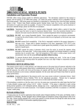
5
4
3
2*
1
6*
7
SERVICE Repair kits are readily available to repair standard 5000 series pumps. Repair kits include simple illustrated instructions allowing easy
installation. To insure that the correct kit is received, the model number and all name plate data must be included with the order. Visit our web
site, contact a SHURflo distributor or contact SHURFLO directly to order the necessary repair kits.
CAUTION To prevent electrical shock, disconnect power before initiating any work. In the case of pump failure, the motor housing and/or the
pumped fluid may carry high voltage to components normally considered safe.
*Male pump ports shown. Female ports
available based on pump model number.
RETURN POLICY
All Industrial pumps/products must be flushed of any chemical (ref. OSHA Section 1910.1200 (d)(e)(f)(g)(h)) and hazardous chemicals must be labeled/tagged
before being shipped* to SHURFLO for service or warranty consideration. SHURFLO reserves the right to request a Material Safety Data Sheet from the returnee
for any pump/product it deems necessary. SHURFLO reserves the right to "disposition as scrap" pumps/products returned which contain unknown fluids.
SHURFLO reserves the right to charge the returnee for any and all costs incurred for chemical testing, and proper disposal of components containing unknown
fluids. SHURFLO requires this in order to protect the environment and personnel from the hazards of handling unknown fluids.
LIMITED WARRANTY PROCEDURE
SHURFLO warrants Industrial 5000 series pumps to be free from material and workmanship defects (under normal use and service) for a period of one (1) year from
the date of manufacture, or (1) one year use with proof of purchase, not to exceed (2) two years in any event.
The limited warranty will not apply to pumps that were improperly installed, misapplied, or incompatible with fluids or components not manufactured by SHURFLO.
SHURFLO will not warrant any pump which is damaged or modified outside the SHURFLO factory.
All Industrial pumps/products must be flushed of any chemicals before shipping*. All warranty considerations are governed by SHURFLO's written Return Policy.
Returns are to be shipped postage prepaid to our service center in Elkhart, IN. SHURFLO shall not be liable for freight damage incurred during shipping. Package
returns carefully. PENTAIR-SHURFLO, 52748 Park Six Ct., Elkhart, IN 46514.
Upon receiving a pump, it will be tested per SHURFLO's test criteria. SHURFLO's obligation under this warranty policy is limited to the repair or replacement of the
unit. Pumps found not defective (under the terms of this limited warranty) are subject to charges to be paid by the returnee for the testing and packaging of "tested
good" units.
No credit or labor allowances will be given to the returnee for pumps returned as defective. Warranty replacements will be shipped on a freight allowed basis.
SHURFLO reserves the right to choose the method of transportation.
This limited warranty is in lieu of all other warranties, expressed or implied, and no other person is authorized to give any other warranty or assume obligation or
liability on SHURFLO's behalf. SHURFLO shall not be liable for any labor, damage or other expense, nor shall SHURFLO be liable for any indirect, incidental or
consequential damages of any kind incurred by the reason of the use or sale of any defective product or part. This limited warranty covers pumps distributed within
the United States of America. Other world market areas should consult with their local distributor for any deviation from this document.
*Carriers, including U.S.P.S., airlines, UPS, ground freight, etc., require specific identification of any hazardous materials being shipped. Check with your shipping
company for specific instructions. Failure to do so may result in substantial penalties.
SHURFLO
3545 Harbor Gateway South, Ste. 103, Costa Mesa, CA 92626, (800) 854-3218 www.shurflo.com
SHURFLO Europe, Middle East, Africa
Pentair Water Belgium bvba, Industriepark Wolfstee, Toekomstlaan 30, B-2200 Herentals, Belgium, +32-14-283500
All Pentair trademarks and logos are owned by Pentair, Inc. All other brand or product names are trademarks or registered marks of their respective owners.
Because we are continuously improving our products and services, Pentair reserves the right to change specifications without prior notice.
Pentair is an equal opportunity employer.
911-1046 Rev B 05/14 ©Pentair, Inc. All rights Reserved.
Number
Description
1
Pressure Switch
1,2*
Upper Assembly
3
Valve Assembly
4
Drive Assembly
5
Motor/Gasket
6* (1,2*,3,4,7)
Pump Head
7
Check Valve
/