Page is loading ...


ZUWA Impeller Pumps
3
Contents
1. Declaration of conformity...................................................................................4
2. Introduction........................................................................................................5
2.1 Further applicable documents........................................................................5
2.2 Legend...........................................................................................................5
2.3 General safety instructions.............................................................................6
3. Construction and functionality............................................................................6
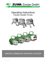
3.1 Pump types....................................................................................................6
3.2 Designs..........................................................................................................6
3.3 Technical Data...............................................................................................7
3.4 Type plate ......................................................................................................8
3.5 Impeller materials...........................................................................................9
4. Transportation and unpacking ...........................................................................9
5. Installation and connection................................................................................9
5.1 Assembly .......................................................................................................9
5.2 Connection of hoses or pipes.......................................................................10
5.3 Electrical connection ....................................................................................10
5.3.1 Series 2000-A and 2000-B....................................................................10
5.3.2 Series 2001-A and 2001-B....................................................................11
6. Commissioning................................................................................................12
7. Storage............................................................................................................13
8. Maintenance....................................................................................................14
8.1 Routine inspection........................................................................................14
8.2 Disassembling the pump..............................................................................14
8.2.1 Series 2000-A and 2000-B....................................................................14
8.2.2 Series 2001-A and 2001-B....................................................................14
8.3 Replacing components.................................................................................14
8.4 Assembling the pump...................................................................................15
8.4.1 Series 2000-A and 2000-B....................................................................15
8.4.2 Series 2001-A and 2001-B....................................................................15
9. Accessories .....................................................................................................16
9.1 Dry run protection.........................................................................................16
9.2 Flow control..................................................................................................16
9.3 Mechanical pressure switch.........................................................................17
9.4 Tool for changing the impeller......................................................................17
10. Troubleshooting...............................................................................................18
11. Environmentally friendly disposal.....................................................................18
12. Performance curves.........................................................................................19

ZUWA Impeller Pumps
4
1. Declaration of conformity
Declaration of conformity according to EC Directives:
98/37/EC (Machinery);
89/336/EEC with subsequent amendments (Electromagnetic Compatibility);
73/23/EEC amended by 93/68/EEC (Low Voltage);
2000/14/EC (Noise Emissions for Outdoor Equipment)
The manufacturer,
ZUWA - Zumpe GmbH, 83410 Laufen, Germany,
hereby declares that the pump models listed below for the decanting of non-flammable
or explosive liquids comply with the provisions of the above-mentioned CE Directives.
The following harmonised and national standards and technical specifications have
been applied:
EN 292-1-91 Safety of Machinery
EN 292-2/A1-95 Safety of Machinery
EN 294-92 Safety of Machinery
EN 61000-6-1 Electromagnetic Compatibility
EN 61000-6-3 Electromagnetic Compatibility
EN 60034-1-1998 Rotating Electrical Machines
EN 55014-1-00 (A1/01; A2/02) Electromagnetic Compatibility
EN 55014-2-97 Electromagnetic Compatibility
EN 60204-1-00 Safety of Machinery
EN 60034-5-01 Rotating Electrical Machines
EN 60335-2-41 Household and similar electrical appliances Safety: Particular
requirements for pumps
Pump model designations:
UNISTAR 2000-A impeller pump UNISTAR 2000-B impeller pump
COMBISTAR 2000-A impeller pump COMBISTAR 2000-B impeller pump
NIROSTAR 2000-A impeller pump NIROSTAR 2000-B impeller pump
Laufen, 21/07/2008
Helmut Wimmer CEO

ZUWA Impeller Pumps
5
2. Introduction
These operating instructions apply for the following pump models/series:
with motor without motor
UNISTAR 2000-A UNISTAR 2001-A
UNISTAR 2000-B UNISTAR 2001-B
COMBISTAR 2000-A COMBISTAR 2001-A
COMBISTAR 2000-B COMBISTAR 2001-B
NIROSTAR 2000-A NIROSTAR 2001-A
NIROSTAR 2000-B NIROSTAR 2001-B
2.1 Further applicable documents
Parts list with exploded drawings
Dimensions
2.2 Legend
Danger of death and severe injury
> Follow all instructions marked with this safety symbol without fail, in
order to prevent risk of injury or death!
Danger of light bodily injuries and material damage
Information, note

ZUWA Impeller Pumps
6
2.3 General safety instructions
The manufacturer shall not be held liable for damage resulting from non-
adherence to the operating instructions.
Store these instructions in such a way that they are accessible at all times for
pump operating personnel. Urge employees to read and follow these instructions.
Do not remove adhesive labels showing technical information.
Observe plant-related specifications and provisions.
Have work carried out by specialist personnel or personnel briefed according to
the VDE standard.
Only carry out work on the pump when the pump is not in operation and the drive
has been disconnected from the mains power supply.
In case of dangerous (e.g. hot, poisonous, explosive) pumped media, use
protective equipment.
Do not pump any liquids that are corrosive to the pump material.
Do not pump any liquids containing particles of diameter greater than 2 mm.
Do not use pumps under water.
Do not allow pumps to run without liquid for longer than one minute.
Only use genuine replacement parts, otherwise the warranty shall cease to be
valid.
3. Construction and functionality
3.1 Pump types
UNISTAR Universal pump with aluminium housing for pumping clean or
contaminated liquids not containing abrasive substances (for
media which are neither abrasive nor corrosive).
COMBISTAR Pump made from stainless steel (all parts which come into
contact with the liquid) and aluminium (cover), also suitable for
abrasive or slightly corrosive liquids.
NIROSTAR Stainless steel pump that is particularly suitable for corrosive
and abrasive liquids, as well as for food and drinks.
3.2 Designs
All of the pumps are available in the following designs:
without motor, with bare shaft (series 2001-A and 2001-B)
as a complete unit with drive motor, coupling and coupling protection (series 2000-
A and 2000-B)

ZUWA Impeller Pumps
7
3.3 Technical Data
UNISTAR 2000-A
UNISTAR 2001-A
UNISTAR 2000-B
UNISTAR 2001-B
COMBISTAR 2000-A
COMBISTAR 2001-A
COMBISTAR 2000-B
COMBISTAR 2001-B
NIROSTAR 2000-A
NIROSTAR 2001-A
NIROSTAR 2000-B
NIROSTAR 2001-B
Max. flow rate in
L/min 30 30 60 60 30 30 60 60 30 30 60 60
Max. pressure 4 bar
Connections
In/Out (inches
and nominal width in
mm)
¾"
19 ¾"
19 1"
20 1"
20 ¾"
19 ¾"
19 1"
20 1"
20 ¾"
19 ¾"
19 1"
20 1"
20
Max. speed 12 or 24-Volt motors: 3,000 rpm
230- or 400-Volt motors: 2,800 rpm
Max. temperature 90 °C
Max. suction height 7 metres (dry 3 metres)
Max. viscosity of
pumped medium 20.000 mPas
Sound pressure level 74 dB

ZUWA Impeller Pumps
8
3.4 Type plate
Type plate, example:
Sleeve
(2nd digit)
1 Plastic
2
3
4
5
6 Aluminium
7 Brass
8 Stainless steel
Impeller
(1st digit)
1 NBR
2 EPDM
3 FKM
4 CR
5 VQM
6 Aluminium
7 Brass
8 Stainless steel
Drive:
00 without motor, bare
shaft end
01 double bearing with V-
belt drive
02 hydraulic drive
14 DC 12 V
24 DC 24 V
34 DC 48 V
63 electr. motor 230 V
with special shaft
64 electr. motor 230 V
with standard shaft
73 electr. motor 400 V
with special shaft
74 electr. motor 400 V
with standard shaft
Seal material
(2nd digit)
Shaft gasket:
1 NBR
2 EPDM
3 FKM
4 CR
5 VQM
Slide ring seal:
1 Stainless steel-graphite-NBR
2 Tungsten-carbide-NBR
3 Tun
g
sten-carbide-Viton
Seal type
(1st digit)
1 Shaft
gasket
2 Slide
ring seal

ZUWA Impeller Pumps
9
3.5 Impeller materials
Impeller pumps are equipped with NBR impellers as standard.
Material designation Suitable for: Properties
NBR
Acrylonitrile butadiene rubber
(Perbunan®, Buna-N®)
Diesel, mineral oils and
greases High impact elasticity and
good mechanical strength
Good for applications
involving high pressures
EPDM
Ethylene propylene diene
rubber (Keltan®, Buna EP®)
High temperatures,
acids and alkalis High elasticity and very
good mechanical stability
CR
Chloroprene rubber
(Neoprene®, Bayprene®)
Food, drinks
Highly flammable,
tearproof, durable
FKM or FPM
Fluorocarbon rubber (Viton®,
Fluorel®)
High temperatures,
acids and alkalis Very good chemical
resistance, low mechanical
strength
4. Transportation and unpacking
> After unpacking, immediately check the pump for completeness and damage.
> Immediately report any transit damage to the supplying company.
> Dispose of packaging material according to the respective local regulations.
5. Installation and connection
5.1 Assembly
Danger
Danger of death due to electric shock
> Work on the electrics may only be carried out by specialist personnel.
Danger
Danger of injury from rotating components
> Cover drive and pump shaft.
Caution
Material damage due to overheating of engine
> Ensure sufficient space and air supply for the motor.

ZUWA Impeller Pumps
10
The pump can be fitted vertically or horizontally. In case of vertical fitting, it is
advantageous to direct the pump head downwards, so that in case of a
pump defect the motor is protected against escaping liquid.
5.2 Connection of hoses or pipes
Hoses or lines must be suitable for the respective pumped medium.
Avoid long suction lines.
Observe correct direction of rotation of pump, indicated
by an arrow on the pump housing and the lettering In –
Out.
Affix hoses as follows:
1. Screw suction line onto the side marked “Ein”.
2. Screw pressure line onto the side marked “Aus”.
3. Verify that the connections are leaktight.
In the case of a suction height of more than 3 metres, fit foot valve in the
suction line in order to prevent drainage of the pump and suction line.
5.3 Electrical connection
5.3.1 Series 2000-A and 2000-B
Danger
Danger of death due to electric shock
> Fit the pump’s electric circuit with a ground fault circuit interrupter.
> Fit a motor overload switch.
230 Volt motors:
Thermal protection is fitted. Fitting of a motor overload switch is advisable.
400 Volt motors:
No thermal protection is fitted. Fitting of a motor overload switch is essential.
Direct current motors:
Protection against overcurrent by means of safety fuses:
12 Volt motors: 80-A
24 Volt motors: 50-A

ZUWA Impeller Pumps
11
Caution
Motor damage can arise due to unsuitable extension cable
> For extension cables of length up to 20 metres: Use cables with at
least the same cross section as the pump cable.
> For extension cables with a length of more than 20 metres: Use cables
with a larger cross section than the pump cable.
5.3.2 Series 2001-A and 2001-B
The pumps can, for example, be driven with the following drive systems:
Power drill
V-belt drive
Gear motor
Hydraulic motor
Air pressure motor
Ensure correct speed and output of the drive system:
When using external drive systems, observe the manufacturer’s instructions.
Max. speed 3000 rpm
Minimum output of the drive system:
370 Watt for types of series 2001-A
550 Watt for types of series 2001-B
Impeller pumps require an increased starting torque.
For pumps with three-phase motor, observe the
direction of rotation of the motor. The direction of
rotation is indicated by an arrow on the pump
housing.

ZUWA Impeller Pumps
12
Operation with hand drill
For operation of the pump with a hand drill, a
stepped support is necessary (see Fig.). The
height of the step must be such that the pump
shaft - drill connection is in a horizontal plane.
1. Screw pump onto the support.
2. Push drill onto the pump shaft. The
pump and the drill should be precisely
aligned.
3. Tighten the chuck.
Caution
Material damage due to pressure on the shaft
> Do not affix the drill to the support, but allow it to lie loosely in such a
way that it has some play.
Operation using other drive systems
If an external drive is being used, a claw coupling with adapter for the connection of
the pump with the motor (optional accessories, see parts list from item 200) is
necessary.
Caution
Material damage due to incorrect alignment of the pump
> If the claw coupling is being used, ensure precise alignment of the
pump and motor, to prevent the shaft from breaking. The claw coupling
can only compensate a degree of play of 0.1 mm.
6. Commissioning
Danger
Danger of death due to explosion
> Do not pump any liquids with a flash point of less than 55 ° C.
> Do not pump petrol or solvents.
Danger
Danger of death and injury due to rotating parts
> Do not touch pump while it is in operation.
Danger
Danger of injury due to items of clothing and hair being caught in the
running drive
> Do not wear loose items of clothing such as ties, scarves and shawls.
> Tie back long hair and protect using a head covering or hood.

ZUWA Impeller Pumps
13
Warning
Danger of injury and poisoning due to dangerous pumped media
> Safely collect escaping pumped media and dispose of in an
environmentally-friendly manner.
Caution
Material damage due to high temperatures of the pumped medium
> Do not pump liquids with a temperature of more than 90 °C, otherwise
the impeller material will become attacked.
Caution
Material damage due to dry running
> In case of a suction depth of more than 3 metres, fill prior to
commissioning.
ZUWA impeller pumps are self-priming, thus, in case of a suction depth of up
to 3 metres, it is not necessary to fill the pump prior to commissioning.
> Open pressure line.
> To start the pump, switch on drive.
During the intake process, the pressure side must not be closed, otherwise
intake will not be possible
Caution
Material damage due to overpressure in the pump
> Do not block pressure side for more than a minute while the drive is
running.
Caution
Material damage due to dry running
> Never allow the pump to run dry for more than one minute.
All ZUWA impeller pumps are suitable for continuous operation.
After extended periods of pump down time prior to commissioning, check that
the impeller wheel runs freely and that the pump starts. See also chapter
Fehler! Verweisquelle konnte nicht gefunden werden.: “Troubleshooting”.
7. Storage
> Empty pump completely
> Clean pump in order to avoid adhesions and damage to the impeller
> Store pump under frost-protected conditions

ZUWA Impeller Pumps
14
8. Maintenance
Danger
Danger of death due to electric shock
> Prior to work on the pump, always disconnect the drive from the power
supply.
8.1 Routine inspection
> Regularly check the line connections for leaktightness (particularly on intake side)
8.2 Disassembling the pump
8.2.1 Series 2000-A and 2000-B
1. Disconnect line connections
2. Unscrew bolts on the pump side
3. Remove cover and side disc (lateral discs only on UNISTAR and
COMBISTAR pumps)
4. Pull housing with impeller and rear side disc off the shaft
8.2.2 Series 2001-A and 2001-B
1. Disconnect line connections
2. Remove bolts and nuts
3. Remove feet
4. Remove cover with shaft and lateral discs on both sides (no lateral discs in
NIROSTAR pumps)
8.3 Replacing components
rotation
Outlet
Intake
Impeller
1. Push impeller out of the casing
2. Insert a new impeller. Observe
direction of impeller vanes (see
adjacent illustration): Impeller wings
must be bent to the opposite side of
the rotating direction.
To change the impeller more easily there is a
tool. See chapter 9.4 „Impeller tool“.
Lateral discs
> Turn around or replace
The pumps of the NIROSTAR series are not fitted with lateral discs.

ZUWA Impeller Pumps
15
Seals
Replace O-rings and push firmly into the recesses
Replacing shaft gasket:
1. Remove retaining ring with suitable pliers
2. Push out bearing and shaft gasket
3. Push in new shaft gasket and bearing
4. Insert retaining rings
8.4 Assembling the pump
8.4.1 Series 2000-A and 2000-B
Assembly of the pump is the reverse of disassembly – see exploded drawing.
1. Connect side disc with punched hole at the rear of the casing (no lateral discs
in NIROSTAR pumps)
2. Push casing with impeller onto the shaft
3. Place front side disc into the recess and push cover onto this
4. Insert and tighten bolts
5. Attach lines
The lateral discs and O-rings must lie precisely in the recesses to ensure
that the O-rings are not pinched.
8.4.2 Series 2001-A and 2001-B
Assembly of the pump is the reverse of disassembly – see exploded drawing.
1. Reapply lateral discs and covers and press on (no lateral discs in NIROSTAR
pumps)
2. Tighten both of the shorter bolts on the thread side using the nuts
3. Affix both feet
4. Insert both of the longer bolts on the bottom and tighten with the nuts
5. Attach lines
The lateral discs and O-rings must lie precisely in the recesses to ensure
that the O-rings are not pinched.

ZUWA Impeller Pumps
16
9. Accessories
9.1 Dry run protection Dry run protection keeps the Impeller from
overheating when running dry.
reset button
In a dry run periode the pump heats up. A thermo
sensitive switch stops the motor at approximately
70°C. After cooling to 60°C the pump can be
restarted.
> After waiting for a short time push the red reset
button to restart the pump.
Do not pump liquids with a temperature of
70°C or more as this would activate the dry
run protection!
9.2 Flow control With the flow control the flow rate of the pump
can be controlled and adjusted to a specific
quantity.
setting
screw
Flow rate measurement is based on the
principle of a floater connected to a spring.
The flow meter is integrated in the housing.
The flow rate can be adjusted with a setting
screw:
> Adjust the setting screw using the scale
from 1 - 6
> Fine adjustment: turn the setting screw
when pump is operating until the required
flow rate is shown in the vision panel.
Technical data
flow rate: 2 – 8 L/min
(for A-types) 8 -30 L/min
(for A-types) 10 – 40 L/min
(for B-types)
connecting thread: 2 x ¾“ a 2 x 1" a 2 x 1" a
max. media temperature: 100°C
max. working pressure: 10 bar
material: brass (approved for drinking water)

ZUWA Impeller Pumps
17
9.3 Mechanical pressure switch
The pressure switch stops the pump once the
preset pressure of 3 bar is reached (top switching
point). When pressure reaches the lower switching
point the pump will start automatically. Switch
hysteresis is set to 30% as standard.
connector plug
The top switching point can be adjusted with the
setting screw located beneath the connector plug.
> Remove connector plug and turn setting screw
with a small screw driver:
- turn right for higher pressure
- turn left for lower pressure
Switch hysteresis can not be adjusted.
Technical data
p
ressure switch and
connector
p
lu
g
setting screw
switch pressure: adjustable from 1 – 10 bar
switch current: 4 A
connecting thread: 1/4"
protection class: IP 65 with plug
switch box: stainless steel or brass
membrane: FKM as standard
9.4 Tool for changing the impeller
A useful tool to install the impeller easily into the casing. Suitable for all ZUWA
impellers.

ZUWA Impeller Pumps
18
10. Troubleshooting
Fault Possible cause Remedy
Intake line is not leaktight Seal connection or line
Impeller worn or damaged Replace impeller
Suction line or foot valve is
blocked Clean suction line or foot
valve
Pump does not take in
liquid
Pressure line closed or
blocked Open fittings on the pressure
side or clean pressure line
Pump does not build up
pressure Impeller or lateral discs are
worn Replace impeller or lateral
discs
Liquid escapes from the
pump Shaft gasket or O-ring is
missing or defective Check whether part is in place
and insert or replace defective
component
Impeller blocked Fill pump with the medium to
be pumped
Impeller clogged up or
macerated
Use an impeller appropriate to
the medium
Pump does not start
Motor defective Have motor checked by
specialist personnel and have
repaired if necessary
11. Environmentally friendly disposal
> Dispose of pumps according to locally applicable regulations.
Plastic parts can be contaminated by toxic pumped media, to the extent that
cleaning is no longer an adequate solution.
Warning
Danger of poisoning and environmental damage due to hazardous
pumped media
> Collect escaping pumped media and dispose of according to the
locally applicable regulations.
> Neutralise residues from the pumped media.


ZUWA-Zumpe GmbH
Franz-Fuchs-Straße 13 - 17 • D-83410 Laufen
Telefon: +49 8682 8934-0 • Fax: +49 8682 8934-34
E-Mail: [email protected] • Internet: www.zuwa.de
© 2008 ZUWA
/