
Oakley Sound Systems
Power Supply Unit (PSU)
PCB Issue 4
Project Builder's Guide
V4.4
Tony Allgood
Oakley Sound Systems
CARLISLE
United Kingdom
1

Introduction
This is the Project Builder's Guide for issue 4 of the PSU circuit board from Oakley Sound.
This document hopefully contains everything you need to know to build and install the Oakley
power supply unit.
The PSU allows for various options in the installation. You can use the unit either in full wave
rectification mode for connection to tapped linelumps or twin transformer secondaries, or in
half wave rectification for single phase AC output wallwarts and linelumps. If all this sounds
very confusing at the moment, do not worry, in this manual I will try to make it clearer so that
you make the right decision about what power source you will need.
It is designed to be mounted onto a metal panel which is used as a heatsink for the two power
devices used on the board. Mounting your power supply to a metal panel on the outside of
your case helps keep your modular cool.
For general information regarding where to get parts and suggested part numbers please see
our useful Parts Guide at http://www.oakleysound.com/parts.pdf.
For general information on how to build our modules, including circuit board population,
mounting front panel components and making up board interconnects please see our
Construction Guide at http://www.oakleysound.com/construct.pdf.
2

Safety Warning
The PSU has been designed to work with isolated low voltage AC inputs. Connection to any
other supply, such as an internally mounted mains transformer, is done at your own risk. Low
voltage is classified as being less than 25V with respect to the ground potential. Voltages
above this level can, and often are, lethal to living creatures.
Oakley Sound Systems will not advise on building or modifying this board to allow for direct
connection to the mains, or other high voltage sources, further to what is provided in this
document. Please do not ask me for any additional information pertaining to direct mains
connections or using internally mounted transformers as I will not give it.
For safety and legal reasons I cannot recommend powering this board from any other
supply than low voltage AC output mains adapters.
Oakley Sound Systems are not liable for any damages caused by the misuse of this product. It
is your responsibility to use this product safely. If you have any doubt about installing a safe
power supply, then please do not attempt to do so.
3

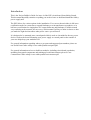
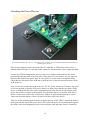
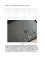
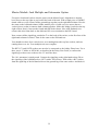
The Oakley Power Supply Board
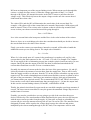
The issue 4 PSU board from Oakley Sound Systems.
The power supply board will allow the conversion of a suitable low voltage alternating current
(AC) to be rectified, smoothed and regulated for operation with the Oakley Modular. The
module is designed to be fitted to a suitably large metal panel which functions as a heatsink for
the series pass devices connected to the PSU circuit board. This metal panel should have
adequate airflow around it. An example of such a panel is the 3U wide master panel which
also contains a handy multiple and power switch. You can also use a 4U or 5U high 19” rack
blank panel. These are particularly suitable if you are mounting your modular synth in a 19”
rack. The greater surface area on the 19” blank panel allows you to mount not only the power
supply module but also up to two Dizzy PCBs. And the greater surface area also allows the
power supply's power devices to dissipate more heat safely and that means a greater current
output should you need it.
The voltage output of the power supply module is a split rail or bipolar 15V supply. This
means it generates both +15V and -15V. That is, two power rails, one of a positive voltage,
the other a negative one. It's sometimes written as +/-15V. These voltages are measured with
respect to a common ground which is normally connected, via your house's wiring, to the
earth that you stand on. The voltage across both rails is 30V, with the common ground sitting
exactly in the middle of this at 0V.
The output current capability is the maximum current you can draw out of the power supply.
The current taken from the supply is, for the most part, determined by the amount and type of
modules you are connecting to the power supply. However, the actual patch also has an effect
on the current draw – the more outputs that are connected to inputs increases the current
draw slightly. Also, some LEDs when lit may increase the current draw.
The Oakley PSU features current limiting. This sets the maximum current the power supply
will actually provide. If you try to draw more than the limit the output voltage will fall to
maintain the current at the limit value. The current limit is set by two resistors, R2 and R3, on
4

the PSU board. It is essential that you make the current limit resistors suit your application.
The next section, and also in the parts list of the Builder's Guide, will give details on what
values to use.
I recommend that you use a Yamaha PA-20 or PA-30 power supply. These are neat tidy
external power supplies that keep the dangerous mains voltage away from your modular. The
PA-20 will allow a maximum current of 520mA (0.52A) to be drawn from each rail. While the
PA-30 will allow up to 780mA (0.78A). Remember though you can't use a PA-30 with the 3U
master panel and expect to draw 0.78A out of it without the panel getting too hot. If you are
using the 3U master panel then you should draw no more than 0.52A per rail. Both the PA-20
and PA-30 are centre tapped AC supplies with three wires within their output cable and use a
three pole connector.
Other power supplies are available and they come in lots of different variations. Other than AC
output voltage the two key specifications are output current (please don't call it 'ampage'), and
whether the output is centre tapped or single phase. In almost all cases the outputs of standard
AC output power supplies are single phase. You can tell because they only have a cable with
two wires inside which terminates in a two pole connector.
A single phase AC output supply will allow only you take not much more than a quarter of its
rated current output. For example if you are using a 500mA (or 0.5A) AC wallwart* then the
most current you can take from this power supply module is around 125mA from each rail.
That is, take no more than 125mA from either the +15V supply and 125mA from the -15V
supply.
Various companies make linelumps** with a greater capacity than 500mA. If you can get a
single phase 1A output one than this will be able to drive up to 250mA per rail.
The Oakley PSU can be used with full wave or half wave rectification. The former allows it to
utilise split AC outputs. With full rectification and using a centre tapped power supply the
amount of current taken from each 15V rail can be up to just over half the rated current
output of the power supply. The Yamaha PA-20 supply is rated to give an output voltage of
35Vac (with a centre tap) at a load of 0.94A. Once rectified and smoothed this means that a
maximum current of 0.52A can be drawn from each rail.
Two sets of screw terminal blocks are provided for connecting the low voltage AC power
source to the board and the optional power switch. If you are using a single phase wallwart to
power the PSU module than you need only to use two terminals per terminal block.
The board has four mounting holes for stable placement onto your modular case. Care should
be taken so that the board's various board mounted components do not come into contact with
any part of your modular's enclosure. Use of 10mm hex spacers between the board's bottom
surface and the panel is the preferred option.
The issue 4 PSU board utilises a different way of connecting 0V to the panel than previous
issues. I recommend that the metal panel be securely connected to 0V. Provision on the PSU
board of a chunky screw terminal allows a thick wire connection to be made to a suitable
bonding point on the panel. This is essential if you are using an internal mains transformer but
also has benefits even when you are using an external wallwart or linelump supply.
5

The power supply has two integral fuse holders in case of a problem with the power supply
circuitry itself. Two fuses are needed if you are using full wave rectification, but only one, F2,
is required for ordinary half wave rectification. The fuse type should be a slow blow or anti-
surge type. The size is 20mm. It should be rated at between one and two times the maximum
current of your wallwart. Thus a 500mA AC output mains adapter should have a fuse that is
rated between 500mA and 1A, ideally 750mA. A 1A linelump should have a fuse that is
between 1A and 2A, ideally 1.25A.
Three on-board LEDs, an orange one for +15V, a green one for -15V, and a red one for the
AC input, provide a quick visual reference that all is well. All three LEDs could be fitted
externally to the board and be mounted on a front panel. However, the recommended way is
to mount only the AC indicator on the front of the synthesiser along with the AC power
standby switch. The red LED comes on whenever AC power is applied to the unit.
As we have seen the standard circuit provides two outputs, one at +15V and one at -15V.
Both output voltages can be finely adjusted with just one trimmer. The -15V will
automatically track the output voltage on the +15V.
The output voltages are available from two screw terminal blocks. It is expected that each
terminal block will be connected to one Dizzy board. However, you can with care connect
more than one Dizzy board to each output block. Multiple Dizzy boards should never be
connected in daisy chain fashion. That is, each Dizzy board should always go back to the PSU
separately and with the shortest and thickness wire you can use.
* A wallwart is the vernacular term for a low voltage mains adapter that plugs directly into the
wall. These take the form of a black plastic block that is shaped like an oversized mains plug.
It is called a wart simply because its appearance is somewhat uglier than a normal slimline
plug.
** A linelump does the same job as a wallwart but it generally can handle greater currents.
Because of its increased size it cannot be made so that it will safely fit into a plug socket
directly. Thus the adapter sits in a black plastic box and connects to the wall via a cable and
traditional mains plug. It is therefore a black plastic lump connected to a line. The Yamaha
PA-20 and PA-30 are such linelumps.
6

Our Recommended Power Supply
The safest available option is to use a ready made 'wallwart' or ‘line lump’ supply. As already
mentioned one can use any 15V or 18V AC output wallwart of linelump you can source. The
current capability of the mains adapter will be the chief limiting factor in determining the
maximum current draw of your PSU. For a variety of reasons I recommend the Yamaha PA-
20 and PA-30 supplies.
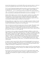
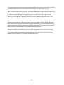
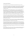
Yamaha PA-20
The European version of the PA-20. Other country's units are similar but will have the local mains
connector fitted.
This is a linelump supply and features a fixed 17.5-0-17.5 volt AC output at 0.94A maximum.
This means it gives us two AC outputs with a centre tap or mid point reference voltage. So
unlike the single phase AC adapter output with two leads, this one has three. This means you
need to use the Oakley PSU in full wave rectification mode.
The PA-20 is made for Yamaha products and they are available from Yamaha spares
departments as well as many music shops, eg. Thomann. These are CE approved and connect
to the mains via your local mains connector. They will be different types depending on the
country you need them for. It comes with a handy three way plug at the low voltage end that
you can use with an appropriate socket. If you wish you can ditch their connector and use
your own. Oakley Sound sell a suitable three way connector to fit the Yamaha one perfectly.
In the UK the line lump’s part number is V9812300 and the total cost is around £30 including
VAT and postage.
7

Once rectified, smoothed and regulated the Yamaha PA-20 can deliver up to 0.52A
continuously into both 15V rails.
You should fit both fuses and both should be anti-surge types and rated at either 1A or 1.25A.
Yamaha PA-30
This is essentially a bigger version of the PA-20 as detailed above which supplies 18V-0-18V
at 1.4A maximum. Once rectified, smoothed and regulated it can supply up to 0.78A
continuously. You should again fit both fuses and both should be 2A anti-surge types.
If you have successfully used the Oakley PSU with any other types of power pack please do
let people know via the Oakley Sound forum at www.muffwiggler.com
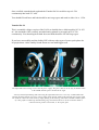
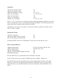
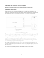
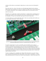
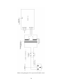
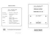
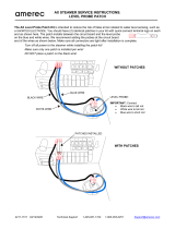
The input and switch wiring to suit a PA-20 power supply. The power inlet is on the left, the DPST switch
in the middle and the power on LED to the right.
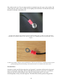
Note my method of mounting and connecting the off board LED. I use a two way 2.54mm Molex KK
housing to hold crimped 7/0.2 wires. These simply slide onto the LED's leads and will stay in place until
one needs to remove the connection by simply pulling on the housing. This 5mm red LED is held in place
by a low profile red LED clip and mounting ring. The LED needs to be wired so that the anode is
connected to the positive connection, ie. the square pad.
8

Which Power Devices?
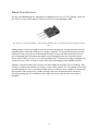
The two recommanded power transistors are chunky devices in a TO-247 package. These are
the TIP35C for the NPN, and the TIP145 or TIP147 for the Darlington PNP.
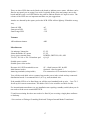
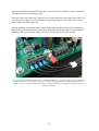
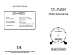
The TO-247 version of the TIP147. Note that the mounting hole is insulated from the metal parts of the
case.
Although they are directly soldered onto the circuit board they are actually mounted onto the
heatsink plate to which the whole power supply is attached. To prevent the metal part on the
underside of the power device from making electrical contact with the heatsink you need to
use an insulating pad. This allows the heat to travel through but not any electrical current.
These will be sold as TO-247 (or TO-3P) insulating pads. You need one pad per transistor but
it may be best to order a couple of extras since they can damaged if not handled carefully.
Obsolete versions of both power devices are still available in the older TO-218 package. This
package is similar in appearance to a larger version of the popular TO-220 package with an all
metal mounting tab. Try to avoid these in this project as they are more complex to mount onto
the heatsink as the fixing screw, washer and nut need to be insulated from the metal tab.
Special mounting kits are available for these older devices but they do take more time to
assemble.
9

Circuit Description
The line lump outputs a two phase AC signal each one with a peak of nearly 25V with respect
to its centre tap output. The difference between the two phases is that one is completely out of
phase with the other. It's a bit like an audio balanced output in that respect. Both phases
should be present for the power supply to work correctly.
Each phase is separately fused. Note that the fuses should be anti-surge, or ‘slo-blo’. The
standard convention is for a ‘T’ in front of the value, where T is for time lag. For example,
T2A would mean a two ampere anti-surge fuse. Anti-surge fuses have a higher thermal mass
than fast blow fuses to prevent them blowing when they see a short burst of current. The
inrush current when the supply is first switched can be very large and we don’t want our fuses
blowing at that point.
D8, C12 and R12 provide a low current DC feed to a standby AC in LED. This lights up
whenever the line lump is connected and powered up. It is wired in before the modular's
power switch to remind you that the power on switch is actually a standby switch and does
not switch the line lump off.
It is possible to run the Oakley PSU module on a single phase. This means that the unit could
be connected to a single output AC adapter, ie. one with just two leads to pins 1 and 2.
However, the regulators and the AC adapter will have to work harder in this application. It is
therefore not recommended to run the PSU in single phase unless the output current is going
to be less than 250mA or so.
The raw AC is fed to a bridge rectifier based around D9, D10, D11 and D12. This is the
classic bridge rectifier circuit. Although it is drawn somewhat differently in the schematic than
the usual ‘bridge’ style. If you think about a diode as passing current through it just one way,
you should be able to work out why the voltage across C13 and C14 ends up as only positive,
and across C7 and C8 as only negative.
I have used 1N5401 diodes in this place. These are 3A devices and are plenty large enough to
cope with any abuse the power supply is given.
The outputs of the rectifiers supply current to the two smoothing capacitors. These act as
reservoirs of charge when the AC voltage dips below its peak output. You can think about the
rectifiers as merely topping up the reservoirs 100 times a second (120 times in North
America), whilst the capacitors actually provide the energy to keep the modular powered.
The smoothing capacitors are generously rated both in terms of voltage and capacitance. It is
essential that you use good quality components here and that they have sufficiently high ripple
current rating. Since this PSU could possibly be supplying up to 1A per supply rail, a single
smoothing capacitor could have nearly 2A running through it. The issue 4 Oakley PSU uses
two smoothing capacitors in parallel per supply rail. The current through each capacitor is,
therefore, roughly half that what it would be with just one larger smoothing capacitor per rail.
This reduces the internal heating of the capacitor thus increasing longevity. Since the
capacitors are in parallel the individual capacitance can be half of what is required for a single
10

capacitor. This reduces the size, normally the height, of the capacitors used, making the whole
PSU assembly physically less high.
The voltage across the smoothing capacitors is fairly constant but it is not stable enough to
drive a modular synth. Modular synths need to have a regulated supply so that they stay in
tune and behave in a predictable fashion whatever patches are selected. The regulators smooth
out the voltage across the big capacitors even more and will produce a constant, low ripple
+15V and -15V output.
Both of the regulators work in a similar way. You can think of them like a person controlling
the speed of a water wheel. If the wheel runs too fast, the water flowing over the wheel is cut
back by closing the sluice gate. If it runs too slowly, then the water flow is increased by
opening the gate. The person uses his own eyes to monitor the speed of the wheel, and will
make adjustments to the sluice accordingly. Now the wheel speed will depend on two things
primarily, firstly the water rate, but also the load on the wheel itself. If the wheel needs to do
more work it will slow down unless the water rate is increased.
The regulated power supply must also control its output with changes of load (ie. the number
of synth modules in your system) and the input voltage (ie. fluctuations in the line lump’s
output).
Before we talk about the circuit in more detail, I ought to say why I haven’t used the more
common and I might add cheaper 7815 and 7915 regulators. The main reason is down to
controllable current limiting. The 78XX and 79XX series do not feature this. In fact, if you
were to short out a 7815 to ground, it would take around 1.7A from the supply and would
heat up until the inbuilt thermal limiter kicked in. 1.7A may well be high enough to damage
any connected transformer or line lump, to say nothing of the rectifiers and smoothing
capacitors that would have to supply this current. By using the LM723 and a few external
components we put the control back in the hands of the builders of the circuit.
Let us look at the positive regulator first since this actually also controls the negative rail too.
The circuit is built around the venerable LM723 chip, U2. It contains pretty much everything
you need to make a small regulator, including precision voltage reference, feedback control
systems and a current limiter. However, it doesn’t have a very big output current capacity so
to use it for anything greater than 100mA, one needs to use an external pass transistor, Q1.
The pass transistor is analogous to our sluice gate. The resistance of the pass transistor is
effectively changed by the voltage at its base (pin 1). Decrease the voltage at its base with
respect to its emitter (pin 3) and the transistor will increase its effective resistance and the
output voltage of the PSU will drop.
The base voltage is controlled by the internal electronics of the LM723, but this in turn
responds to the feedback from the output of the power supply. The feedback path is
analogous to the sluice gate man’s visual record of the water wheel’s motion. In this case a
fraction of the output signal is fed back into the LM723 at pin 4. The electronics will
determine whether to make the base drive for Q1 higher or lower depending on what it ‘sees’.
The ADJ trimmer adjusts the fraction of the output voltage pin 4 will see and thus controls the
overall output voltage.
11

R2 forms an important part of the current limiting circuit. When current travels through this
resistor a voltage develops across it. When the voltage approaches 630mV, ie. 630mA
through a 1R resistor, the internal electronics in the LM723 starts to pull down the base
voltage on Q1. This effectively lowers the output voltage to make sure the current doesn’t
climb much above that value.
The value of R2 (and also R3) will determine the actual value of the current limit. For
example, a 1R resistor will set the current limit to be around 630mA and a 0.82R resistor will
make it around 770mA. The resistor value is chosen so that it will develop around 630mV
across it when your chosen current limit would be going through it.
Ilimit = 0.63V/Rlimit
Ilimit is the current limit value in amperes and the Rlimit is the value in ohms of the resistor.
However, there are several things to be taken into consideration should you decide to increase
the current limit above the values I have chosen.
Firstly, you need to ensure your transformer, internal or external, will be able to handle the
additional current you are asking from it. The simple rule of thumb is:
Iac = 1.8 x Idc.
Where Iac is the steady state AC current in the transformer's secondary coil, and Idc is the
current taken by the load connected to the +15V and -15V rails. For example: The Yamaha
PA-20 can supply 0.94A of alternating current into a simple resistive load from each of its two
outputs. But by the time the output of the PSU has been rectified and smoothed the DC
current taken should not exceed 0.52A on a continuous basis.
Secondly, the amount of current needed to drive the base of the pass transistors, Q1 and Q2,
is directly related to the amount of current draw from the supply lines. Thus to ask for more
from the supply would be to ask more from the 723 on the positive rail and the op-amp on the
negative rail. The actual relationship between load current and drive current is related to hfe or
the gain of the pass transistor. Choosing a pass transistor with too little gain will mean that
you cannot obtain your required current. The recommended TIP35C and TIP145 devices have
been tested to work with a mains transformer that can supply up to 1.1A into the output load.
In this case the current limiting resistors, R2 and R3, would both be 0.56R.
Thirdly, the printed circuit board's copper tracks are not thick enough to pass huge amounts of
current. The more current a track has to carry the greater the unwanted voltage drop across it
and the hotter it becomes.
Fourthly, you need to consider how you are going to get rid of the extra heat the power
devices will develop. The actual amount of heat dissipated by the power devices will increase
with the more current you take from the supply. It is not quite as simple as a doubling of
current will give twice the amount of heat given off, but it is not far off it. The amount of heat
dissipated (in watts) will be equal to the voltage drop between the collector and emitter
multiplied by the current running through it (the DC load). The temperature will rise with
12

increased heat dissipation but a good heatsink will keep the temperature down to a safe level.
If you can't comfortably touch a power device for more than ten seconds it is too hot.
The 3U wide 5U high panel design has only been tested to work with a maximum of 0.52A
per rail when driven from a PA-20 or PA-30. A 4U or 5U high 19” panel is capable of
considerably more – a 4U 19” panel has been tested successfully using a mains transformer
with a 1A load and 25V across the smoothing capacitors. However, I would advise you to do
your own experiments carefully otherwise you run the serious risk of overheating.
Finally, I think modular systems work better with a number of smaller power supplies rather
than one big one. This is because as power is distributed around a large modular it gets
'corrupted' by the connected modules and the cabling. The cables have resistance and as
current flows through the cables the voltage at the end of the cable gets reduced. The more
current that flows and the longer the cable the worse the problem.
Having multiple power supplies does create the not insignificant question of what to do with
the multiple grounds you will now have in your system. These can all be connected together
and later in this document I will present one way of doing this.
Now let us look in more detail at the negative part of the power supply. The negative supply
works in a similar way to the positive regulator but uses an op-amp, U3, and discrete
components. The reference for the negative rails comes not from a precision reference but
from the output of the +15V regulator. This means that the negative output voltage will track
the positive one, but not vice versa I should add.
The op-amp is wired as a simple inverting amplifier although its difficult to see this at first
glance. The input is via R9 which is connected to the +15V output. The feedback is provided
via R8 which is connected to the negative supply output. The output of the op-amp drives the
base of the pass transistor, Q2, via R11, which in turn controls the level of the negative
output. Q2, a TIP145, is a PNP Darlington transistor. This is actually two transistors in one
enclosure – but it can treated as one device with a larger than normal current gain (hfe) and
twice than normal base-emitter voltage of 1.2V. Having a high gain requires only a small
amount of drive current from the op-amp via R11 even when the load on the power supply is
relatively high.
U3 will act so that its output will force all the current flowing through R9 to be passed onto
R8. This is one of the op-amp golden rules; that is, no current shall flow into the input pins so
long as feedback is maintained. To do this the op-amp must force the pass transistor to pass
enough current though it to establish exactly -15V at the output.
Q3 and R3 form part of the current limit circuit. If the voltage across R3 exceeds 640mV then
Q3 will turn on dragging current away from Q2’s base and thus lowering the output voltage of
the negative rail accordingly.
The op-amp U3 derives its positive power from its own 5V supply based around a simple
7805 regulator chip. This allows the negative regulator to function correctly when the +15V
rail is under stress and allows the negative rail to fall gracefully when the mains power is
switched off.
13

D1, D7, D2 and D6 protect the +15V and -15V output rails from a variety of naughties. On
power down any excess current left in the modular will be shunted to the smoothing caps and
not damage the now unpowered power supply components. Also, they also prevent the
negative rail from going positive should the negative rail die for some reason. And vice versa
too.
14

Parts List
For general information regarding where to get parts and suggested part numbers please see
our useful Parts Guide at the project webpage or http://www.oakleysound.com/parts.pdf.
The components are grouped into values, the order of the component names is of no particular
consequence.
A quick note on European part descriptions:
For resistors: R is shorthand for ohm. K is shorthand for kilo-ohm. M is shorthand for mega-
ohm
For capacitors: 1uF = 1,000nF = 1,000,000pF. Sometimes the F is not included on the circuit
diagram to indicate a capacitor's value, ie. 100n = 100nF.
To prevent loss of the small ‘.’as the decimal point, a convention of inserting the unit in its
place is used. eg. 4R7 is a 4.7 ohm, 4K7 is a 4700 ohm resistor, 4n7 is a 4.7 nF capacitor.
Resistors
5% 1/4W carbon or better (1/4W 1% metal film is recommended)
1K R1, R11
4K7 R4, R5, R10
1% 1/4W metal film
10K R7, R9, R8
12K R6, R12
2W metal film or wirewound (5% or better)
For use with the Yamaha PA-20:
1R R2, R3
For use with the Yamaha PA-30:
0R82 R2, R3
15

Capacitors
22pF low-K ceramic 2.5mm C4
330p low-K ceramic 2.5mm C5
100nF axial multilayer ceramic C1, C2, C9
10uF, 35V electrolytic C3, C6, C10, C11
22uF, 35V electrolytic C12
470uF, 35V electrolytic C15
1800uF, 35V electrolytic C7, C8, C13, C14
Note: C7, C8, C13 and C14 are 105 degree Celsius radial types and have standard wire ended
leads. Lead spacing is 7.5mm. I recommend Panasonic type EEUFC1V182 but any decent 105
degree part can be used that will fit on the board will do.
Alternatively, you can use two 3300uF, 35V instead. Fit these to positions C8 and C14 and
leave C7 and C13 empty.
Integrated Circuits
7805 5V 1A regulator U1
LM723CN 100mA voltage regulator U2
OP177GPZ single precision op-amp U3
Good quality DIL sockets are recommended. You need one 14-pin and one 8-pin.
Discrete Semiconductors
1N4004 rectifier diode D1, D2, D3, D4, D5, D6, D7, D8
1N5401 rectifier diode D9, D10, D11, D12
TIP35C NPN transistor Q1
TIP145 or TIP147 PNP Darlington transistor Q2
BC560 PNP transistor Q3
Do not solder the Q1 or Q2 until the board is mounted on its panel
For D1 to D8 you can use any other 1N400X part such as 1N4001, 1N4002, etc.
D9 and D10 do not need to be fitted if you are using a single phase wall wart or line lump.
However, for full wave rectification D9 and D10 are required. So if you are using a split
output line lump, or an internal transformer with twin secondaries, D9 and D10 have to be
fitted.
16

There are three LEDs that can be fitted to the board to indicate power status. All three can be
fitted to any panel you are using if you wish. I typically fit the green and orange ones to the
board and have only a red LED fitted to the panel to indicate that the AC input is active. The
colours of the LEDs are not important and these are just suggestions.
Anodes are denoted by the square pad on the PCB. LEDs will not light up if fitted the wrong
way.
5mm red LED AC
5mm green LED -VE
5mm orange LED +VE
Trimmer
10K multiturn trimmer ADJ
Miscellaneous
2A antisurge 20mm fuse F1, F2
20mm fuseholder PC mount F1, F2
4-way screw terminal 5mm POWER, SWITCH, OP1, OP2
TO-247, TO-218 or TO-3P insulator pad. Q1, Q2
Suitable power switch
Suitable power inlet socket
Keystone 8191 PCB terminal & screw 0V – fitted between OP1 & OP2
4mm 'banana' socket Optional – fitted on panel. *
4mm ring terminals (crimp/solder) For connection of 0V terminal to bond point. *
You will also need thick wire to connect between the power inlet, switch and any connected
distribution boards. I recommend 24/0.2 (0.75 sq. mm) insulated wire.
If the standby LED is to be fitted then you will also need standard hook up wire – I use 7/0.2
for all my low current connections. The thicker 24/0.2 wire would be too thick for this.
For internal mains transformer (or any installation not requiring a standby switch) then you do
not need to fit the screw terminal SWITCH.
F1 and its associating fuse does not need to be fitted if you are using a single phase wallwart
or linelump.
* See sections on 'Fitting a Grounding Point' and 'Using an Internal Mains Transformer'.
17

Mounting hardware for Master Panel
M3 10mm countersunk screws 4 off Panel front side
M3 6mm pan head screws 4 off PCB top side
M3 20mm countersunk screws 2 off For power devices
M3 hex threaded 10mm spacers 4 off
M3 star washers 10 off
M3 washers 6 off For PCB and power devices
M3 hex nuts 2 off For power devices
Mounting hardware for 19” rack panel
M3 6mm pan head screws 8 off
M3 20mm pan head screws 2 off For power devices
M3 hex threaded 10mm spacers 4 off
M3 star washers 10 off
M3 plain washers 6 off For PCB and power devices
M3 hex nuts 2 off For power devices
M4 16mm pan head screw 1 off For 0V/Earth bond point
M4 washer 2 off For 0V/Earth bond point
M4 star washer 2 off For 0V/Earth bond point
And any mounting hardware for the Dizzy boards if needed.
Master Panel - Jack Multiple, CV/gate and Attenuator Option
Switchcraft 1/4” sockets 112A 12 off
47K 5% or better, 0.25W resistors 1 off
4K7 5% or better, 0.25W resistors 1 off
20AWG tinned copper wire Approx. 1m
For Oakley Bus:
3-way Molex/MTA housing 1 off – also Molex crimps if using a Molex housing.
A suitable length of hook up wire
18

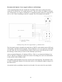
Attaching the Power Devices
The PSU board fitted to a 4U 19” rack panel. Note the blue TO-247 insulator pads underneath the two
chunky power devices.
This section assumes you have purchased the 3U Schaeffer or FPE master panel or have a
suitably drilled 5U high 19” rack panel onto which you will mount the power supply assembly.
For the four PCB mounting holes, insert a 6mm screw (10mm countersunk for the master
panel design) through each of the four holes in the panel. Fit a star washer over the exposed
thread on the inside of the panel. Now fit a hex spacer over the washer and tighten firmly.
Check that the four holes in the PCB line up with the tops of the hex spacers but don’t fit the
PCB in just yet.
Now you need to prepare the leads on the two TO-247 power transistors. The three legs need
to be bent upwards so that the PCB can be fitted over them. Note that the top surface of the
device is marked with the name of the component and it is the flat side on the bottom of the
device that will be in contact with the panel. You should be able to see that the leads have a
thicker section close to the body of the device. Make a 90 degree bend upwards at a point
1mm away from this thicker section. Do this for all three legs of the device.
Take one of the insulating pads and place it against the rear of the TIP35C. Match up the hole
in the pad with the hole in the power device. Now place the power device and pad flat against
the inside of the panel aligning the holes of the transistor, pad and panel. Insert a 20mm M3
19

screw (countersunk for the master panel design) into the hole from the front, and fit a washer,
star washer and nut onto the screw but keep it loose. Do the same for the TIP145.
Now if you have done all this correctly, you should find that the when the power supply PCB
is aligned once more, you can coax the power devices’ legs through the respective pads on the
board. You will probably have to wiggle the power devices about a bit to get it to fit
smoothly. Check that the transistors' leads have not been pushed downwards at all – they
should not be touching the metal panel.
Place a star washer on a 6mm screw and a plain washer over that. Place into one of the PCB's
mounting holes and screw into the hex spacer but do not tighten. Do this for the other three
holes. Now secure the transistors in place by tightening the nuts. Do not overtighten. All you
need to make sure is that the transistor sits firmly to the panel. If you tighten it too much the
device will lift at one end and not sit flat against the insulating pad.
Then gently tighten the board's four screws. Again, all you need to do is secure the board.
You can now solder the transistor leads from the top side of the board. Any excess lead
lengths can be cut down as you would a normal component.
20
Page is loading ...
Page is loading ...
Page is loading ...
Page is loading ...
Page is loading ...
Page is loading ...
Page is loading ...
Page is loading ...
Page is loading ...
Page is loading ...
Page is loading ...
Page is loading ...
Page is loading ...
Page is loading ...
-
 1
1
-
 2
2
-
 3
3
-
 4
4
-
 5
5
-
 6
6
-
 7
7
-
 8
8
-
 9
9
-
 10
10
-
 11
11
-
 12
12
-
 13
13
-
 14
14
-
 15
15
-
 16
16
-
 17
17
-
 18
18
-
 19
19
-
 20
20
-
 21
21
-
 22
22
-
 23
23
-
 24
24
-
 25
25
-
 26
26
-
 27
27
-
 28
28
-
 29
29
-
 30
30
-
 31
31
-
 32
32
-
 33
33
-
 34
34


Ask a question and I''ll find the answer in the document
Finding information in a document is now easier with AI
Other documents
-
 Acnodes KD8220 Owner's manual
-
Acroprint RS485-DB25 Modular Jack Adapter Owner's manual
-
 Musical Fidelity X-PSUv3 User manual
-
Yupiteru MVT-7100 Owner's manual
-
Rane MA 6 Schematic
-
-
 Musical Fidelity X-PSU User manual
-
WARRIOR Sequential Operating instructions
-
 Amerec AX Steamer Operating instructions
-
Premiere MT106 Operating instructions


