Page is loading ...

Service Manual
ORDER NO. SIMMC 0001002C1
E1
Microwave Oven
© 2000 Shanghai Matsushita Microwave
Oven Co.,Ltd
All rights reserved. Unauthorized copying
and distribution is a violation of law.
MODELS APH CPH
USA Canada
®
Specifications:
Power Source:
Power Requirement:
Output(IEC705-88):
Microwave Frequency:
Timer:
Outside Dimensions:
Oven Cavity Dimensions:
Weight:
Output power:IEC705-88 Test Procedure
Specifications subject to change without notice.
Specifications for APH :
Model:
*120V AC Single Phase, 60Hz
*2450MHz
*99min.99sec
*20
”(518mm)(W)O16
”(407mm)(D)O11”(301mm)(H)
*14
”(375mm)(W)O15
”(386mm)(D)O8
”(225mm)(H)
*26.5 lbs. (12.0kg)
1370W 1370W 1370W 1370W
1300W 1300W 1100W 1000W
NN-S560BF/WF NN-S550BF/WF NN-S540BF/WF NN-L530BF/WF
Specifications:
Power Source:
Power Requirement:
Output(IEC705-88):
Microwave Frequency:
Timer:
Outside Dimensions:
Oven Cavity Dimensions:
Weight:
Output power:IEC705-88 Test Procedure
Specifications subject to change without notice.
Specifications for CPH:
Model:
*120V AC Single Phase, 60Hz
*2450MHz
*99min.99sec
*20
”(518mm)(W)O16
”(407mm)(D)O11”(301mm)(H)
*14
”(375mm)(W)O15
”(386mm)(D)O8
”(225mm)(H)
*26.5 lbs. (12.0kg)
1370W 1370W 1370W 1370W 1370W
1200W 1100W 1100W 1100W 1000W
NN-S560BF/WF NN-S540BF/WF NN-L530WF NN-L520WF NN-S510WF
NN-S560BF/WF
NN-S550BF/WF
NN-S540BF/WF
NN-L530BF
NN-L530WF
NN-L520WF
NN-S510WF
* RPH Model refer to the last page.

WARNING
CONTENTS
(Page) (Page)
-1-
FEATURE CHART ...........................................................................3 DISASSEMBLY AND PARTS REPLACEMENT PROCEDURE ............... 13
CONTROL PANEL ...........................................................................3 COMPONENT TEST PROCEDURE ........................................................ 16
OPERATION AND DIGITAL PROGRAMMER MEASUREMENTS AND ADJUSTMENTS ............................................... 18
CIRCUIT TEST PROCEDURE ........................................................5 PROCEDURE FOR MEASURING MICROWAVE ENERGY LEAKAGE...19
SCHEMATIC DIAGRAMS ............................................................... 7 TROUBLESHOOTING GUIDE .................................................................20
DESCRIPTION OF OPERATING SEQUENCE ...............................9 EXPLODED VIEW AND PARTS LIST ......................................................24
CAUTIONS TO BE OBSERVED WHEN TROUBLESHOOTING ....11 SCHEMATIC DIAGRAM &
PARTS LIST OF DIGITAL PROGRAMMER CIRCUIT ............................. 25
PRECAUTIONS TO BE OBSERVED BEFORE AND
DURING SERVICING TO AVOID POSSIBLE EXPOSURE
TO EXCESSIVE MICROWAVE ENERGY
(A) Do not operate or allow the oven to be operated with the
door open.
(B) Make the following safety checks on all ovens to be serviced
before activating the magnetron or other microwave source,
and make repairs as necessary:
(1) Interlock operation
(2) Proper door closing
(3) Seal and sealing surfaces (arcing, wear, and other
damage)
(4) Damage to or loosening of hinges and latches.
(5) Evidence of dropping or abuse
(C) Before turning on microwave power for any service test or
inspection within the microwave generating compartments,
check the magnetron, waveguide or transmission line, and
cavity for proper alignment, integrity and connections.
(D) Any defective or misadjusted components in the interlock,
monitor, door seal, and microwave generation and trans-
mission systems shall be repaired, replaced, or adjusted
by procedures described in this manual before the oven is
released to the owner.
(E) A microwave leakage check to verify compliance with the
Federal Performance Standard should be performed on
each oven prior to release to the owner.
WARNING
This service information is designed for experienced repair technicians only and is not designed for use by the general public. It does not
contain warnings or cautions to advise non-technical individuals of potential dangers in attempting to service a product.
Products powered by electricity should be serviced or repaired only by experienced professional technicians. Any attempt to service or repair
the product or products dealt with in this service information by anyone else could result in serious injury or death.
>
1.This product should be serviced only by trained, qualified personnel.
2.Though this product has been manufactured in compliance with:
“Federal Performance Standard 21 CFR Subchapter J”(D.H.H.S): U.S.A. models
or “Radiation Emitting Devices Act”(Health and Welfare Canada): Canadian models
it is very important all repairs should be made in accordance with procedures described in this manual to avoid being exposed
to excessive microwave radiation.
3.Check for radiation leakage before and after every servicing according to the “procedure for measuring radiation leakage.”
4.If the unit cannot be repaired on site, advise the customer not to use until unit is repaired.
5.Any serviceman who learns of any accident pertaining to microwave radiation leakage including the oven operating with
open door should immediately notify the appropriate address listed below and Center for Devices and Radiological Health,
DHHS.
IN U.S.A. Panasonic Services Company IN PUERTO RICO PSC
(PASC) 50 Meadowland Parkway, (PSC) San Gabriel Industrial Park
Secaucus, New Jersey 07094 65th Infantry Ave. Km.9.5
Attention: Technical Service Division. Carolina, Puerto Rico 00985
(201)348-7000 (787)750-4300
IN CANADA Panasonic Canada Inc.
(PCI) 5770 Ambler Drive, Mississauga,
Ontario, L4W2T3
(905)624-5010
6.There are special components used in the microwave oven which are important for safety. These parts are marked with
a on the replacement parts list. It is essential that these critical parts should be replaced only with the manufacture’s
specified parts to prevent microwave leakage, shock, fire, or other hazards. Do not modify the orginal design.
>

DANGER OF HIGH VOLTAGE AND HIGH TEMPERATURE (HOT/LIVE) OF THE INVERTER POWER SUPPLY (U)
INVERTER WARNING
This Inverter board looks like a regular PCB. However, this PCB drives the magnetron tube with extremely high voltage
and high current.
IT HAS: 1. Very high voltage and high current circuits.
It functions the same as the high voltage transformer and high voltage capacitor in ordinary microwave ovens.
2. Aluminum heat sink is energized with very high voltages and high heat energy.
3. Very high voltage may remain in circuitry even when oven is off. High voltage may remain in the capacitors
on the board.
DO NOT:
1. Do not touch circuitry because it has very hot (high voltage) circuitry. Even when replacing board, extreme
care should be taken to avoid possible electric shock hazards. High voltage may remain in circuit.
2. Do not touch aluminum heat sink because it is very hot in high voltage and also very hot in high heat energy.
3. Do not try to adjust or tamper with preset volume on the Inverter board because it is very dangerous to
adjust without proper test equipment.
4. Do not test oven while Inverter grounding plate or screws are loose. It is very dangerous to operate H.V.
Inverter Circuit (U) with loose mounting screws or if improperly grounded.
5. For USA only:
Do not try to repair Inverter PCB because it is very dangerous to repair it. Replace as whole High Voltage
Inverter Circuit unit and return fully re-packed with original shipping box and shipping materials.
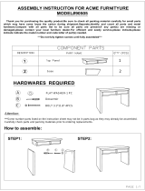
INVERTER POWER SUPPLY DIAGRAM
NEW HV
- 2 -
*
*
*
*
*
HEAT SINK
(RECTIFIER BRIDGE)
CHOKE COIL
CURRENT
TRANSFORMER
SAND BAR
RESISTOR
HIGH VOLTAGE
TRANSFORMER
PCB
FILM CAPACITORS
VARISTOR
PRIMARY WINDINGS
SECONDARY
WINDINGS
HIGH VOLTAGE
DIODES
DO NOT TOUCH
LEAD
WIRE
GROUNDING
PLATE * 4
INVERTER
SUPPORT
BRACKET OF ORIFICE
H.V INVERTER(U) * 3

1
2
5
7
11
16
17
4aa
aa
a
9
12
3
8
6
10
FEATURE CHART
- 3 -
CONTROL PANEL
FEATURE
Three Stage Cooking
Inverter Turbo Defrost
Auto Reheat
Inverter Auto Cook
Sensor Reheat
Sensor Cook
Quick Min
Popcorn
Timer
Digital Clock
MODEL NN-S550WF NN-S540WF NN-S510WF
NN-S520WFNN-S530WF
NN-S560WF
NN-S560(CPH)
NN-S560(APH)
1
2
5
7
11
16
17
3
8
6
12
9
NN-S550
7
1
24bb
bb
b
17
3
6
16
11
5
8
10
k
lb
oz
Popcorn
Inverter
Turbo
Defrost
(lb/k )
Auto
Reheat
(1-4servings)
Inverter Auto Cooking
Power
Level
(10 Levels)
Quick
Min
Start
Stop /
Reset
123
654
789
Clock
0
Timer
Froz.Veg.
11.
Froz.
Entrées
8.
Breakfast
(-)
13
Dinner
67
(-)
FreshVeg.
10.
Serving
/
Weight
Rice
12.
Potatoes
9.
Lunch
45
(-)
4aa
aa
a

- 4 -
CONTROL PANEL
NN-L520
7
1
24b
17
3
13
6
16
11
5
8
14
15
NN-L530
1
24b
17
3
13
6
16
11
5
8
7
14
15
(1) Display Windows
(2) Popcorn Pad
(3) Inverter Turbo Defrost Pad
(4a) Sensor Reheat Pad
(4b) Auto Reheat Pad
(5) Power Level Pad
(6) Number Pads
(7) Timer Pad
(8) Clock Pad
(9) Sensor Cook Pad
(10) Inverter Auto Cooking Pads
(11) Quick Min Pad
(12) More /Less Pad
(13) Cooking Guide
(14) Auto Cook Pad
(15) Serving/Weight Pad
Before cooking: One tap clears your instructions.
During cooking: One tap temporarily stops the
cooking process. Another tap cancels all your
instructions and time of day or colon appears on
the display window.
(17) Stop/Reset Pad
One tap allows oven to begin functioning. If door is
opened or STOP/RESET Pad is pressed once during
oven operation, START Pad must again be pressed to
restart oven.
(16) Start Pad
5
MN-S510
7
1
24b
17
3
6
16
11
8
10
NN-S540
7
1
24b
17
3
6
16
11
5
8
10

- 5 -
OPERATION AND DIGITAL PROGRAMMER CIRCUIT TEST PROCEDURE
When you pluge the power supply cord into the wall outlet, microwave oven automatically enter into the state of lb / oz. If you want
to use g / kg state, please press Start pad after pluging the power source.
1. Press Inverter Turbo Defrost
pad.
2. Set the weight for 1 lb by press-
ing Number pads.
1 lb = 1 0
3. Press Start Pad.
4. Press Stop/Reset Pad twice.
Oven shuts off.
8. When 2nd stage cooking time has
elapsed, oven beeps 5 times and
shuts off.
Time of day or colon if set appears
in the display.
3. Inverter Turbo Defrost
OPERATION SCROLL DISPLAY
OPERATION SCROLL DISPLAY
Time of day or colon if set appears
in the display.
4.23
1.0
1. Press Rice pad twice.
2. Press Start pad.
Cooking begins as time counts
down.
3. When cooking time has elapsed,
oven beeps 5 times and shuts off.
4. Inverter Auto Cooking
OPERATION SCROLL DISPLAY
15.00
2. Press Power Level pad once
to set High power.
(1st stage)
3. Set for 5 seconds by pressing
Number pads.
5 sec.= 5
4. Press Power Level pad 4 times
to set Medium power.
(2nd stage)
5. Set for 1 minute by pressing
Number pads.
1 min.= 1 0 0
6. Press Start pad.
7. When 1st stage cooking time has
elapsed. Oven beeps twice and
automatically switches to 2nd
stage cooking.
OPERATION SCROLL DISPLAY
1. Plug the power supply cord into
wall outlet.
2. Press Clock pad.
3. Enter time of day (TOD) by press-
ing appropriate Number pads.
4. Press Clock pad. TOD has now
been resistered into the digital
programmer circuit and will count
up by minutes.
2. Time Cooking for Two Stage
OPERATION SCROLL DISPLAY
1. Place a water load in the oven.
88.88
11 25
11. 25
1.0 0
P 1 0
. 5
P 5
. 5
1.0 0
1. To Set Clock
1
Time of day or colon if set appers in
the display.
1. Press Auto Cook pad.
2. Press Number pads.
(Press 3 to select Bacon)
5. Auto Cook
OPERATION SCROLL DISPLAY
3
6

- 6 -
OPERATION SCROLL DISPLAY
3. Press Serving / Weight pad.
(Select 4. 6. 10. 14 slices)
4. Press Start pad.
When cooking time has elapsed,
Oven beeps 5 times and shuts off.
4
4.10
Times of day or colon if set appears
in the display.
OPERATION SCROLL DISPLAY
1. Press Popcom pad five times
for 3.5 oz serving.
(Select 1.75. 2.65. 2.85. 3.0 or
3.5 oz )
2. Press Start pad.
Cooking begin as times counts
down.
When cooking time has elapsed,
Oven beeps 5 times and shuts off.
3.5
1.45
Time of day or colon if set appears in
the display.
6. Popcorn
OPERATION SCROLL DISPLAY
1. Pour 150 15cc (4.5 1/2 ozs)
of room temperature water in a
beaker, place the beaker in the
center of the oven.
Press Breakfast pad twice.
2. Press Start pad.
3.The steam sensor detects steam
about 1.5 to 4 minutes after the
start pad is pressed.
Sensor cooking (T1) automatically
switches to cooking time(T2).
“Sensor” disappears with beep
sounds and the remainder of
cooking time appears in the display
window.
NOTE: Cooking time will vary
depending on the water
temperature, the shape of
the beaker or the Power
source Voltage.
4.When cooking time has elapsed,
Oven beeps 5 times and shuts off.
2
Time of day or colon if set appears in
the display.
7. Sensor Cooking (NN-S560WFAPH/CPH,S560BFAPH/CPH)
OPERATION SCROLL DISPLAY
1. Press Auto Reheat pad twice
for two servings.
2. Press Start pad.Auto Reheat
cycle begins time counts down.
3.When cooking time has elapsed,
Oven beeps 5 times and shuts off.
2
2.00
Time of day or colon if set appears in
the display.
8. Auto Reheat
Press
Power Level
9. Power Level
Power Level Display Window
once
twics
3 times
4 times
5 times
6 times
7 times
8 times
9 times
10 times
P 10 (HIGH)
P 9
P 8
P 7 (MED. HIGH)
P 6 (MEDIUM)
P 5
P 4
P 3 (MEDIUM-LOW)
P 2
P 1 (LOW)
P 10
P 9
P 8
P 7
P 6
P 5
P 4
P 3
P 2
P 1
OPERATION SCROLL DISPLAY
1. Press Start pad 3 times
continuously. “Child” appears in
the display.
Child
10. To set Child satety Lock
OPERATION SCROLL DISPLAY
1. Press Start / Reset pad 3 times
continuously.
11. To Reset Child Lock
Time of day or colon if set appears in
the display.

SCHEMATIC DIAGRAM (APH)
- 7 -
SCHEMATIC DIAGRAM (APH)

- 8 -
SCHEMATIC DIAGRAM (CPH)
SCHEMATIC DIAGRAM (CPH)

DESCRIPTION OF OPERATING SEQUENCE
1. Variable power cooking control
The coil of power relay B (RY1) is energized intermittently by the digital
programmer circuit, when the oven is set at any power selection except
for High power position. The digital programmer circuit controls the
ON-OFF time of power relay B contacts in order to vary the output
power of the microwave oven from ”Low” to “High” power. One
complete ON and OFF cycle of power relay B is 22 seconds. The
relation between indications on the control panel and the output of the
microwave oven is as shown in table.
NOTE: The ON/OFF time ratio does not correspond with the
percentage of microwave power since approximately 2 sec-
onds are required for heating of magnetron filament.
2. Inverter Power Supply Circuit NEW H,V
This Inverter Power Supply Circuit supplies 4,000V DC to the magnetron
tube from the line voltage,120v 60Hz AC input. functions as the H.V.
transformer, the H.V.capacitor and H.V.Diode.
1. The AC input voLtage 120V 60HZ is rectified to DC voltage immediately.
2. DC voltage will be supplied to the switching devices called IGBT. These
devices will be switched ON-OFF by the 20 to 40 kHz PWM. (pulse
width modulation) signal from the microcomputer in the DPC.
3. This drives the High voltage transformer to increase up to 2,000V AC
and approximately 3V AC by means of transformer.
4. Then the half-wave doubler voltage rectifier circuit, consisting of the
HV diodes and Capacitors, generates the necessary 4,000V DC
needed for the magnetron.
5. Output power of the magnetron tube is always monitored by the
signal output from the current transformer built into the inverter ciruit.
6. Then this signal will be fed back to the microcomputer in the DPC to
determine operating conditions and output necessary to control PWM
signal to the inverter Power Supply to control output power.
3. Inverter Turbo Defrost
When this Auto Control feature is selected and the Start Pad is tapped:
(A) The digital programer circuit determines the power level and cooking
time to complete cooking and indicates the operating state in the
display window. Table shows the corresponding cooking times for
respective serving by categories.
(B) When cooking time the display window has elapsed, the oven tums
off automatically by a control signal from the digital programmer circuit.
- 9 -
POWER SETTING
OUTPUT
POWER(%)
APPROX.
ON-OFF TIME OF
POWER RELAY B (RY1)
ON (SEC) OFF (SEC)
HIGH
MEDIUM-HIGH
MEDIUM
MEDIUM-LOW
DEFROST
100%
90%
80%
70%
60%
50%
40%
30%
20%
10%
30%
22
22
22
22
22
22
22
22
15
8
22
0
0
0
0
0
0
0
0
7
14
0
Variable Power Cooking
P10
P9
P8
P7
P6
P5
P4
P3
P2
P1
P3
Inverter Turbo Defrost
SELECTED
WEIGHT
1.0LB
6.0LB
COOKING TIME
4 min.28 sec.
25 min.00 sec.

4. Sensor Cooking (NN-S560BFAPH/CPH NN-
S560WFAPH/CPH)
Auto sensor cooking is a revolutionary way to cook by microwave
without setting a power level or selecting a time.
All that is necessary is to select an Auto Sensor Program before starting
to cook.
Understanding Auto Sensor Cooking
As the food cooks, a certain amount of steam is produced. If the food
is covered, this steam builds up and eventually escapes from the
container. In Auto Sensor Cooking, a carefully designed instrument,
called the steam sensor element, senses this escape of steam. Then,
based upon the Auto Sensor Program Selected, the unit will
automatically determine the correct power level and the proper length
of time it will take to cook the food.
NOTE: Auto Sensor Cooking is successful with the foods and
recipes found in the Auto Sensor Cooking Guide. Because
of the vast differences in food composition, items not
mentioned in the Cooking Guide should be prepared in the
microwave oven using power select and time features. Please
consult variable Power Microwave cookbook for procedures.
Explanation of the Auto Sensor Cooking process
1) During the first 10 second period there is no microwave activity,
and when calculating the T2 time by using the formula below make
sure this 10 second is subtracted from the T1 time. In other words T1
time starts at the end of the 10 second period.
2) T1 time... The total amount of time it takes the microwave oven to
switch to T2 time after the 10 second period.
3) T2 time... When the steam escapes from the cooking container placed
in the oven, the steam sensor detects it and the microprocessor cal-
culates the balance of cooking time. This T2 time is then shown in the
display and begins counting down.
Balance of cooking time (T2 time)
The balance of cooking time which is called T2 time, can be calcu-
lated by the following formula.
T2 time (in sec.)=T1 time X K factor
NOTE: Remember, the T1 time starts after the 10 second period.
The coefficient K is programmed Into the mlcroprocessor
memory and they are listed in the following tables along with
the P1 and P2 powers.
NOTE: When "More" or "Less" pad is selected, the K factor varles
resulting In T2 time to be increased or decreased.
Example of calculating the T2 time
Example 1: If the T1 time is measured to be 2 minutes and 40 seconds
after the 10 second period, and the Auto program selected is
Frozen Vegetable:
T2 = T1 X K
=2 min. and 40 sec. X 0.1
=160 sec. X 0.1
=16 sec.
5. Sensor Reheat (NN-S560BFAPH/CPH,NN-S560WF
APH/CPH)
Auto Sensor Reheat is a quick and easy way to reheat refrigerator
and room temperature foods.
Simply press the reheat pad. There is no need to select power level
and cooking time.
NOTE: The Auto Sensor Reheat process is same as Auto Sensor
Cooking process.
AUTO SENSOR COOKING/REHEAT PROCESS
Category
Frozen Vegetables
Sensor Cooking
P1
Power
HIGH
K Factor
Standard
0.1
P2
Power
LOW
- 10 -
Category
Sensor Recheat
Sensor Reheat (All Sensor Modeis)
P1
Power
HIGH
K Factor
Standard
0.1
P2
Power
LOW

CAUTIONS TO BE OBSERVED WHEN TROUBLESHOOTING
Unlike many other appliances, the microwave oven is high-voltage, high
current equipment. Though it is free from danger in ordinary use, extreme
care should be taken during repair.
1. Check the grounding
Do not operate on a 2-wire extension cord. The microwave oven is
designed to be used when grounded. It is inoperative, therefore, to
make sure it is grounded properly before beginning repair work.
2. Inverter Warnings
CAUTION
Servicemen should remove their watches whenever
working close to or replacing the magnetron.
DANGER OF HIGH VOLTAGE AND HIGH
TEMPERATURE (HOT/LIVE) OF THE INVERTER
POWER SUPPLY (U)
This High Voltage Inverter Power Supply circuit supplies
very high voltage and very high current for the magnetron
tube. Though it is free from danger in ordinary use, extreme
care should be taken during repair. As you can see, it looks
like a TV flyback transformer, however the current is
extremely large and so danger exists because of its high
current and high voltages.
The aluminum heat sink is also energized with high voltage
(HOT), so do not touch when AC input terminal is connected
to the power line because one of the IGBT switching power
devices (Collector) is directly connected to the Aluminum
heat sink.
The Aluminum heat sink may be HOT from heat energy;
therefore, extreme care should be taken during servicing
and replacing.
WARNING OF INVERTER POWER SUPPLY (U)
GROUNDING
Check the High Voltage Inverter Power Supply circuit grounding.
This High Voltage Inverter Power Supply circuit board must have
a proper chassis ground by the grounding bracket to the chassis
ground; otherwise, this H.V. Inverter circuit board will expose
very high voltage and cause extreme DANGER! Be sure to have
proper grounding by the grounding plate and screws.
WARNING OF DISCHARGING HIGH VOLTAGE
CAPACITORS
Warning about the electric charge in the high voltage capacitors.
For about 30 seconds after the oven is turned off, an electric charge
remains in the high voltage capacitors in the inverter power supply
circuit board.
When replacing or checking parts, remove the power plug from
the outlet and short the Inverter output terminal of the magnetron
filament terminals to the chassis ground with an insulated handle
screwdriver to discharge. Please make sure to touch chassis
ground side first then short to the output terminals.
WARNING
There is high-voltage present, with high-current capabilities in the
circuits of the primary, and secondary windings, choke coil and
heat sink of the Inverter. It is extremely dangerous to work on or
near these circuits with oven energized.
DO NOT measure the voltage in the high voltage circuit including
filament voltage of magnetron.
WARNING
Never touch any circuit wiring with your hand nor with an
insulated tool during operation.
3. When parts must be replaced, remove the power
plug from the outlet.
4.When the 18 Amp fuse is blown due to the operation
of short switch:
(A) This is mandatory. Refer to “Measurements and Adjustments”
for these switches.
(B) When replacing the fuse, confirm that it has the appropriate
rating for these models.
(C) When replacing faulty switches, be sure mounting tabs are
not bent, broken or otherwise deficient in their ability to hold
the switches.
5.Avoid inserting nails, wire, etc. through any holes in
the unit during operation.
Never insert a wire, nail or any other metal object through the
lamp holes on the cavity or any other holes or gaps, because
such objects may work as an antenna and cause microwave
leakage.
WARNING
When the 18 Amp. fuse if blown due to the operation of
short switch, you must replace Primary latch switch and
short switch. Also replace power relay B (RY1) when the
continuity check reads shorted contacts (1-2).
MAGNETRON
FILAMENT TERMINAL
INSULATED HANDLE
SCREWDRIVER
Touch chassis side first then short to the terminal of the magnetron
filament terminal.
- 11 -
NEW H.V.

6.Confirm after repair
(A) After repair or replacement of parts, make sure that the screws of the
oven, etc. are neither loose nor missing.
Microwaves might leak if screws are not properly tightened.
(B) Make sure that all electrical connections are tight before inserting the
plug into the wall outlet.
(C) Check for microwave energy leakage. (Refer to procedure for measuring
microwave energy leakage.)
CAUTION
MICROWAVE RADIATION
DO NOT BECOME EXPOSED TO RADIATION FROM THE
MICROWAVE GENERATOR OR OTHER PARTS CONDUCTING
MICROWAVE ENERGY.
IMPORTANT NOTICE
1. The following components have potentials above 250V while the
appliance is operating..
h Magnetron
h High voltage transformer (Located on Inverter (U))
h High voltage diodes (Located on Inverter (U))
h High voltage capacitors (Located on Inverter (U))
Pay special attention on these portions.
2. When the appliance is operated with the door hinges or magnetron
fixed incorrectly, the microwave leakage can reach more than
5mW/cm2. After repair or exchange, it is very important to check if
magnetron and the door hinges are correctly fixed.
NEW H.V.
- 12 -
*
*
*
*

- 13 -
DISASSEMBLY AND PARTS REPLACEMENT PROCEDURE
1. Magnetron
(A) Discharge the high voltage capacitors, as mentioned and shown on page 11.
(B) Remove 1 screw holding air guide c to magnetron.
(C) Disconnect 2 high voltage lead wires from magnetron filament terminals.
(D) Remove 4 screws holding the magnetron.
NOTE: After replacement of the magnetron, tighten mounting screws in an X
pattern, properly making sure there is no gap between the waveguide
and the magnetron to prevent microwave leakage.
2. Digital Programmer Circuit (DPC) and membrane key board.
NOTE: Be sure to ground any static electric charge built up on your body before
handling the DPC.
(A) Disconnect all connectors from D.P.C.
(B) Slide the escutcheon base upward slightly.
(C) Remove 1 screws holding DPC
To replace membrane key board
(F) Push the upper part of key board (display window portion) from back of
escutcheon base and peel off escutcheon sheet and membrane key
board completely from escutcheon base.
NOTE: 1. The membrane key board is attached to the escutcheon base with
double faced adhesive tape. Therefore, applying hot air such as using a
hair dryer is recommended for smoother removal.
2. When installing new membrane key board, make sure that the surface
of escutcheon base is cleaned sufficiently so that any problems (shorted
contacts or uneven surface) can be avoided.
3. Alignment position of membrane key board is as follows;
Membrane key board: Right and upper edges
Escutcheon sheet: Right and upper edges
3. Low voltage transformer and/or power relays (RY1, RY2)
NOTE: Be sure to ground any static electric charge built up on your body before
handling the DPC.
(A) Using solder wick or a desoldering tool and 30W soldering iron, carefully
remove all solder from the terminal pins of the low voltage transformer
and/or power relays.
NOTE: Do not use a soldering iron or desoldering tool of more than 30 watts on
DPC contacts.
(B) With all the terminal pins cleaned and separated from DPC contacts, remove
the defective transformer/power relays and install new transformer/relays
making sure all terminal pins are inserted completely. Resolder all terminal
contacts carefully.
4. Fan motor
(A) Disconnect 2 lead wires from fan motor terminals.
(B) Remove 1 screw at located on oven attaching orifice assembly.
(C) Remove orifice assembly/Inverter power supply (U) from oven assembly.
(Refer page 15)
(D) Remove fan blade from the fan motor shaft by pulling it straight out.
(E) Remove 2 screws holding fan motor to orifice.
(F) Separate the fan motor from the orifice assembly by freeing 2 catch hooks on
the orifice assembly.
CAUTION
When replacing the magnetron, be sure the antenna
gasket is in place.
SCREW

- 14 -
5. Door assembly
(A) Remove door C from door E by carefully pulling outward starting from
upper right hand corner using a flat blade screwdriver.
(B) Separate door E from tabs on door A and remove door A.
(C) Open Door E at the opening angle of approximately 10° (Note: The door
cannot be removed if the opening angle is greater than 10°).
(D) Remove the door from its hinges by pushing the door’s lower hinge pin
upward and out.
(E) Remove door screen B from door A.
(F) Remove door key and door key spring.
(G) When reassembling door hold door E at the opening angle of approximately
10°.
(H) Place the door’s lower hinge pin into the bottom hinge hole.
(I) Use your left index finger to support the door’s lower hinge pin while guiding
the door’s upper hinge pin into the top hinge hole.
(J) Lower your finger to seat the door onto the hinges.
(K) Replace other components.
(L) Door alignment is crucial. If door is misaligned, apply pressure
until alignment is achieved.
After replacement of the defective component parts of the door,
reassemble, install, and perform microwave leakage test.
6. Turntable motor
(A) Remove the motor cover by breaking off at the 8 spots indicated by arrows with
a cutter or the like. (See Figure)
NOTE: After breaking off the motor cover, make sure that cut-off
portions are properly trimmed off or bend to inside so that
no sharp edge will expose to outside.
(B) Disconnect 2 lead wires connected to the turntable motor.
(C) Remove the turntable motor by removing 1 screw.
NOTE: After reinstalling the new turntable motor and reconnecting
the two lead wires, reinstall the motor cover by rotating it around 180 ,
tucking the tabs under the base into the 2 provided slots, then screw the
single tab to the base using a 4mm X 6mm screw (not provided).
7. Steam Sensor
(A) Remove 1 screw holding steam sensor unit. (indicated by arrows)
(B) Disconnect CN2 connector from digital programmer circuit board.
(C) Remove exhaust guide from steam sensor unit.
(D) Remove catch hooks on sensor mounting plate and air guide.
(E) Remove steam sensor from sensor mounting plate.
NOTE: When installing the steam sensor, make sure that the
direction of steam sensor is as shown in figure.
DOOR
CCREEN B
DOOR A
DOOR
KEY
DOOR
KEY
SPRING
DOOR E DOOR C
BASE MOTOR
COVER
01-046

- 15 -
8. Inverter Power Supply (U)
CAUTIONS WHILE REPLACING INVERTER POWER SUPPLY (U)
1. Make sure to leave the grounding plate in its place.
2. Make sure to securely tighten grounding screw from the
bottom of chasis (base).
3. Securely connect 3 lead wire connectors.
4. Make sure the heat sink has enough space (gap) from the
oven. Take special care not to touch any lead wire to the
aluminum heat sink because it is hot.
1. Take off outer panel.
2. Remove screw
4. Disconnect all wires from inverter. Detach turntable wires
from inverter bracket.
3. Remove screw
5. Remove screw and slide oriffice toward you, then lift up and out.
6. Slide four locking of oriffice at the bottom of the base slightly
7. Remove 2 screws holding inverter to inverter bracket.
8. Replace inverter and reassemble to inverter bracket A.
9. Retighten 2 screw
10. Slide and place assembly to the correct location of a completed unit.
11. Push Inverter Assembly until locking tabs are locked.
12. Retighten inverter screws and orifice screws.
13. Reconnet all wires to correct location and redress turntable wires.

COMPONENT TEST PROCEDURE
CAUTION
1. High voltage is present at the high voltage terminal of
the High Voltage Inverter (U) including aluminum heat
sink during any cook cycle.
2. It is neither necessary nor advisable to attempt mea-
surement of the high voltage.
3. Before touching any oven components, or wiring,
always unplug the oven from its power source and
discharge the high voltage capacitors.
NEW. H.V.
1. Primary Latch Switch, Secondary (Secondary Latch
Switch and Power Relay B) Interlocks.
(A) Unplug the lead connectors to Power Relay B and verify continuity
of the power relay B 1-2 terminals.
(B) Unplug lead connectors to Primary Latch Switch and Secondary
Latch Switch.
(C) Test the continuity of switches at door opened and closed positions
with ohm meter (low scale).
Normal continuity readings should be as follows.
2. Short Switch & Monitor
(A) Unplug lead wires from Inverter Power Supply (U) primary terminals.
(B) Connect test probes of ohm meter to the disconnected leads which
were connected to Inverter Power Supply (U).
(C) Test the continuity of short switch with door opened and closed
positions using lowest scale of the ohm meter.
Normal continuity readings should be as follows.
Door Closed
0 Ω (close)
0 Ω (close)
5. Inverter Power Supply (U)for USA only
DO NOT try to REPAIR this H.V. Inverter power supply
(U).Replace as whole H.V. Inverter(U) Unit.
Primary Latch Switch
Secondary Latch Switch
Power Relay B
Door Closed
Ω
Door Opened
0 Ω
- 16 -
3. Magnetron
Continuity checks can only indicate an open filament or a shorted
magnetron. To diagnose for an open filament or shorted
magnetron.
(A) Isolate magnetron from the circuit by disconnecting the leads.
(B) A continuity check across magnetron filament terminals should
indicate one ohm or less.
(C) A continuity check between each filament terminal and magnetron
case should read open.
ANTENNA
COOLING
FIN
MAGNETRON
CASE
HIGHEST
OHM
SCALE
FILAMENT
TERMINALS
04-031M
0Ω-1Ω
RX1
SCALE
ANTENNA GASKET
HEAT SINK
CHOKE COIL
CURRENT
TRANSFORMER
RESISTOR
SAND BAR
PCB
FILM CAPACITORS
VARISTOR
PRIMARY WINDINGS
SECONDARY
WINDINGS
HIGH VOLTAGE
DIODES
DO NOT TOUCH 4
DANGER HIGH VOLTAGE
Test if failure codes of H97 or H98 appears by doing the following
procedure. It is recommended to use an AC line input current
Ampere meter for testing.
Test 1
A. Program DPC.
1. Tap Clock
2. Tap TIMER
3. Tap START
4. Tap POWER LEVEL
B. Place 1 liter of water load into oven cavity.
C. Unplug 2 pin H.V. lead wire connector CN703 from magnetron
tube.
D. Program oven at High power for 1 minute and press start.
1. After approximately 15 seconds, oven displays H98 and
stops oven.
2. During oven operation, input current is approximately 1.0
to 1.7A. If both 1 and 2 are OK, please proceed to test 2.
.
Test 2.
Continued from Test 1
A. Unplug 3 pin connector, CN701
B. Set oven at High power for 1 minute and start.
1. After approximately 27 seconds, oven displays H97 and
stops oven.
2. During oven operation, input current is approximately 0.4
to 0.8A
If both 1 and 2 are OK, the Inverter Power Supply (U) can be
determined OK.
FAILURE CODE
H98
FAILURE CODE
H97
Unplug CN703
INPUT AMPERE
1.0 to 1.7A
Unplug CN701
INPUT AMPERE
0.4 to 0.8A
HIGH BOLTAGE
TRANSFORMER
DO NOT TOUCH (HOT/HIGT VOLTAGE)
Door Opened
Ω (open)
Ω (open)
Ω (open)
4. Membrane key board (Membrane switch assembly)
Check continuity between switch terminals, by tapping an appropri-
ate pad on the key board. The contacts assignment of the
respective pads on the key board is as shown in digital programmer
circuit.
Ω (open)

- 17 -
6. Steam Sensor and Digital Programmer Circuit
In order to determine if the steam sensor function of the digital
programmer circuit is in working order or not, do the following
test.
1) Place a water load (150 cc) in the oven.
2) Tap Sensor Reheat pad.
3) Tap Start Pad.
4) Steam Sensor detects steam about 1.5 to 4 minutes after the
Start Pad is tapped.
5) T1 time cooking automatically switches to remaining time cooking
(T2).
6) The remaining cooking time (T2) appears in display window. If
the following cooking time appears, Steam Sensor function is
normal.
T2 TIME
8 Sec.~23 Sec.
T1 TIME
1 Min. 30 Sec.~4 Min.
(Remaining cooking time)

WARNING
1. Adjustment of Primary latch switch, Second-
ary latch switch and Short switch.
(A) When mounting Primary latch switch,Secondary latch switch
and short switch to door hook assembly, mount the Primary latch
switch, the Secondary latch switch and the short switch to the
door hook assembly as shown in table.
NOTE: No specific adjustment during installation of
Primary latch switch, Secondary latch switch and
short switch to the door hook is necessary.
(B) When mounting the door hook assembly to the oven
assembly, adjust the door hook assembly by moving it in the
direction of arrow in the illustration so that the oven door will not
have any play in it. Check for play in the door by pulling the door
assembly. Make sure that the latch keys move smoothly after
adjustment is completed. Completely tighten the screws holding
the door hook assembly to the oven assembly.
(C) Reconnect the short switch and check the continuity of the
monitor circuit and all latch switches again by following the
components test procedures.
2. Measurement of microwave output
The output power of the magnetron can be determined by performing
IEC standard test procedures. However,due to the complexity
of IEC test procedures, it is recommended to test the magnetron
using the simple method outlined below.
Necessary Equipment:
*1 liter beaker *Glass thermometer
*Wrist watch or stopwatch
NOTE: Check the line voltage under load.Low voltage will
lower the magnetron output. Take the temperature
readings and heating time as accurately as possible.
(A) Fill the beaker with exactly one liter of tap water.Stir the water
using the thermometer and record the beaker’s temperature.
(recorded as T1).
(B) Place the beaker on the center of glass cook plate.
Set the oven for High power and heat it for exactly one minute.
(C) Stir the water again and read the temperature of the beaker.
(recorded as T2).
(D) The normal temperature rise at High power position for each
model is as shown in table.
MEASUREMENTS AND ADJUSTMENTS
*For continued protection against radiation hazard,
replace only with identical replacement parts(For touch
models Part No. ANE6142-1450,Type No.
V-16G-3C26-M for Primary latch switch; Part No.
A61425180AP, Type No. L-3C2-2 for Secondary latch
switch; Part No. A61785180AP, Type No. L-2C2-2 for
short switch and Part. No. AEG5J1EG12B/AEG5J1EG18B,
Type No. G5J-1-TP for power relay B(RY1))
*When the 18 Amp. fuse is blown due to the operation of
the short switch, you must replace power relay B.
Primary
latch switch and the short switch. Then follow the installa-
tion procedures below.
*Interlock switch replacement In replacing faulty
switches, be sure mounting tabs are not bent, broken or
otherwise deficient in their ability to hold the switches.
*Refer to schematic diagram to ensure proper connec-
tion.
SWITCH
GAP SHOULD BE <0.7MM.
ACTUATOR
LEVER
SCREW
PRIMARY
LATCH
SWITCH
DOOR HOOK
ASSY
SHORT
SWITCH
SECONDARY
LATCH
SWITCH
SCREW
DOOR
01-033
TABLE (1L-1min. test)
RATED OUTPUT
1000~1100W(IEC705-88)
1200~1300W(IEC705-88)
- 18 -
TEMPERATURE RISE
Min. 16.2oF(9oC)
Min. 17.6oF(9.5oC)

MOVE PROBE ALONG SHADED
AREA( )AROUND EXHAUST
OPENINGS(as shown)AND AROUND
AIR INLET OPENING
PROCEDURE FOR MEASURING MICROWAVE ENERGY LEAKAGE
WARNING
Check for radiation leakage after every servicing. Should
the leakage be more than 2 mW/cm2 (1mW/cm2 for
Canada) inform PASC, PSC, or PCI immediately.
After repairing or replacing any radiation safety device,
keep a written record for future reference, as
required by D.H.H.S. and Health and Welfare Canada
regulation. This requirement must be strictly observed.
In addition, the leakage reading must be recorded on
the service repair ticket while in the customer’s home.
NOTE: The U.S. Government standard is 5 mW/cm2 while in
the customer’s home. 2mW/cm2 stated here is our own
voluntary standard. (1mW/cm2 for Canada)
1. Equipment
*Electromagnatic radiation monitor
*Glass thermometer 212 OF or 100 OC
*600cc glass beaker
2. Procedure for measuring radiation leakage
Note before measuring.
(1) Do not exceed meter full scale deflection. Leakage monitor
should initially be set to the highest scale.
(2) To prevent false readings the test probe should be held by the
grip portion of the handle only and moved along the shaded area
in Figure no faster than 1 inch/sec (2.5cm/sec).
(3) Leakage with the outer panel removed ...... less than 5mW/cm
2
.
(4) Leakage for a fully assembled oven with door normally closed
...... less than 2mW/cm
2
(1mW/cm
2
for Canada).
(5) Leakage for a fully assembled oven [Before the latch switch
(primary) is interrupted] while pulling the door ...... less than
2mW/cm
2
.
(A) Pour 27515cc (9ozss1/2oz) of 20O5 OC (68O9 OF) water in a
beaker which is graduated to 600cc, and place in the center of the
oven.
(B) Set the radiation monitor to 2450MHz and use it following the
manufacturer’s recommended test procedure to assure correct
results.
(C) When measuring the leakage, always use the 2 inch (5cm) spacer
supplied with the probe.
(D) Tap the start pad or set the timer and with the magnetron oscillating,
measure the leakage by holding the probe perpendicular to the
surface being measured.
(1) Measurement with the outer panel removed.
Whenever you replace the magnetron, measure for radiation leakage
before the outer panel is installed and after all necessary components
are replaced or adjusted. Special care should be taken in measur
ing around the magnetron.
WARNING
(2) Measurements with a fully assembled oven.
After all components, including outer panel are fully assembled,
measure for radiation leakage around the door periphery, the
door viewing window, the exhaust opening and air inlet openings.
3. Record keeping and notification after measurement
(A) After any adjustment or repair to a microwave oven, a leakage read-
ing must be taken. Record this leakage reading on the repair ticket
even if it is zero.
A copy of this repair ticket and the microwave leakage reading should
be kept by repair facility.
Avoid contacting any high voltage parts.
(B) Should the radiation leakage be more than 2 mW/cm2 (1mW/cm
for Canada) after determining that all parts are in good
condition, functioning properly, and genuine replacement
parts as listed in this manual have been used, immediately
notify PASC, PSC or PCI.
4. At least once a year, have the radiation
monitor checked for calibration by its
manufacturer.
01-035
- 19 -
WARNING
AVOID CONTACTING ANY HIGH VOLTAGE PARTS.
/