
PMOR30B
PMOR30R
PMOR30S
In the interest of user-safety the oven should be restored to its original condition and only parts identical to those specified should
be used.
WARNING TO SERVICE PERSONNEL: Microwave ovens contain circuitry capable of producing very high voltage
and current. Contact with the following parts may result in a severe, possibly fatal, electrical shock. (Inverter unit
that includes High Voltage Capacitor, High Voltage Power Transformer, High Voltage Rectifier and Heat sink etc.,
and Magnetron, High Voltage Harness etc..)
TABLE OF CONTENTS
Page
PRECAUTIONS TO BE OBSERVED BEFORE AND DURING SERVICING TO
AVOID POSSIBLE EXPOSURE TO EXCESSIVE MICROWAVE ENERGY.................. INSIDE FRONT COVER
BEFORE SERVICING..................................................................................................... INSIDE FRONT COVER
WARNING TO SERVICE PERSONNEL .............................................................................................................. 1
MICROWAVE MEASUREMENT PROCEDURE .................................................................................................. 2
FOREWORD AND WARNING ............................................................................................................................. 3
PRODUCT SPECIFICATIONS............................................................................................................................. 4
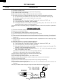
GENERAL INFORMATION ................................................................................................................................. 4
OPERATION ........................................................................................................................................................ 6
TROUBLESHOOTING GUIDE........................................................................................................................... 14
TEST PROCEDURE .......................................................................................................................................... 16
TOUCH CONTROL PANEL ASSEMBLY ........................................................................................................... 27
COMPONENT REPLACEMENT AND ADJUSTMENT PROCEDURE............................................................... 33
PICTORIAL DIAGRAM....................................................................................................................................... 41
POWER UNIT CIRCUIT..................................................................................................................................... 42
LSI UNIT CIRCUIT ............................................................................................................................................. 43
PRINTED WIRING BOARD ............................................................................................................................... 44
PARTS LIST....................................................................................................................................................... 45
PACKING AND ACCESSORIES........................................................................................................................ 50
S00M151PMOR3E
PMOR30B
PMOR30R
PMOR30S
OVER THE RANGE
MICROWAVE OVEN
MODELS
SERVICE MANUAL
This document has been published to be used for after
sales service only.
The contents are subject to change without notice.
distinctive appliances

PMOR30B
PMOR30R
PMOR30S
PRECAUTIONS TO BE OBSERVED BEFORE AND
DURING SERVICING TO AVOID POSSIBLE
EXPOSURE TO EXCESSIVE MICROWAVE ENERGY
(a) Do not operate or allow the oven to be operated with the door open.
(b) Make the following safety checks on all ovens to be serviced before activating the magnetron or other microwave
source, and make repairs as necessary: (1) interlock operation, (2) proper door closing, (3) seal and sealing
surfaces (arcing, wear, and other damage), (4) damage to or loosening of hinges and latches, (5) evidence of
dropping or abuse.
(c) Before turning on microwave power for any service test or inspection within the microwave generating
compartments, check the magnetron, wave guide or transmission line, and cavity for proper alignment, integrity,
and connections.
(d) Any defective or misadjusted components in the interlock, monitor, door seal, and microwave generation and
transmission systems shall be repaired, replaced, or adjusted by procedures described in this manual before the
oven is released to the owner.
(e) A microwave leakage check to verify compliance with the Federal Performance Standard should be performed
on each oven prior to release to the owner.
BEFORE SERVICING
Before servicing an operative unit, perform a microwave emission check as per the Microwave Measure-
ment Procedure outlined in this service manual.
If microwave emissions level is in excess of the specified limit, contact DACOR immediately @
1-800-793-0093.
If the unit operates with the door open, service person should 1) tell the user not to operate the oven and
2) contact DACOR and Food and Drug Administration's Center for Devices and Radiological Health
immediately.
Service personnel should inform DACOR of any certified unit found with emissions in excess of 4mW/cm
2
.
The owner of the unit should be instructed not to use the unit until the oven has been brought into compliance.
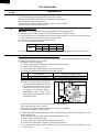
DANGER CAUTION
HIGH VOLTAGE
Do not energize a microwave oven with the outer case cabinet removed, because a microwave oven
generates High Voltage in the circuit.
If you intend to operate the oven employing the high frequency switching power converter circuit, you should
take special precautions to avoid an electrical shock hazard.
The high voltage transformer, high voltage capacitor and high voltage diode have energized high voltage
potential approx. 8 KV.
The aluminium heat sink is connected to the switching power transistor Collector pole, and has an energized
high voltage potential approx. 650V peak.
DO NOT ACCESS THE HIGH VOLTAGE TRANSFORMER, HIGH VOLTAGE CAPACITOR, HIGH
VOLTAGE DIODE AND HEAT SINK WHEN THE POWER SUPPLY IS CONNECTED TO AN ELECTRICAL
OUTLET.

1
PMOR30B
PMOR30R
PMOR30S
WARNING TO SERVICE PERSONNEL
Microwave ovens contain circuitry capable of pro-
ducing very high voltage and current, contact with
following parts
may result in a severe, possibly
fatal, electrical shock.
(Example)
Inverter unit that includes High Voltage Capacitor,
High Voltage Power Transformer, High Voltage
Rectifier, Heat sink etc., and Magnetron, High
Voltage Harness etc..
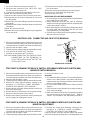
Read the Service Manual carefully and follow all
instructions.
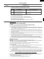
Before Servicing
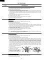
1. Disconnect the power supply cord , and then
remove outer case.
2. Open the door and block it open.
3. To discharge high voltage capacitor, wait for 60 seconds.
WARNING:RISK OF ELECTRIC SHOCK.
DISCHARGE THE HIGH-VOLTAGE
CAPACITOR BEFORE SERVICING.
The high-voltage capacitor remains charged about 60
seconds after the oven has been switched off. Wait for 60
seconds and then short-circuit the connection of the high-
voltage capacitor (that is the connecting lead of the high-
voltage rectifier) against the chassis with the use of an
insulated screwdriver.
Whenever troubleshooting is performed the power supply
must be disconnected. It may in, some cases, be necessary
to connect the power supply after the outer case has been
removed, in this event,
1. Disconnect the power supply cord, and then remove
outer case.
2. Open the door and block it open.
3. To discharge high voltage capacitor, wait for 60 seconds.
4. Disconnect the leads to the primary of the inverter unit.
5. Ensure that these leads remain isolated from other
components and oven chassis by using insulation tape.
6. After that procedure, reconnect the power supply cord.
When the testing is completed,
1. Disconnect the power supply cord, and then remove
outer case.
2. Open the door and block it open.
3. To discharge high voltage capacitor, wait for 60 seconds.
4. Reconnect the leads to the primary of the inverter unit.
5. Reinstall the outer case (cabinet).
6. Reconnect the power supply cord after the outer case is
installed.
7. Run the oven and check all functions.
After repairing
1. Reconnect all leads removed from components during
testing.
2. Reinstall the outer case (cabinet).
3. Reconnect the power supply cord after the outer case is
installed.
4. Run the oven and check all functions.
Microwave ovens should not be run empty. To test for the
presence of microwave energy within a cavity, place a cup
of cold water on the oven turntable, close the door and set
the power to HIGH and set the microwave timer for two (2)
minutes. When the two minutes has elapsed (timer at zero)
carefully check that the water is now hot. If the water
remains cold carry out Before Servicing procedure and re-
examine the connections to the component being tested.
When all service work is completed and the oven is fully
assembled, the microwave power output should be checked
and microwave leakage test should be carried out.
Don't Touch !
Danger High Voltage

2
PMOR30B
PMOR30R
PMOR30S
MICROWAVE MEASUREMENT PROCEDURE
A. Requirements:
1) Microwave leakage limit (Power density limit): The power density of microwave radiation emitted by a microwave oven
should not exceed 1mW/cm
2
at any point 5cm or more from the external surface of the oven, measured prior to acquisition
by a purchaser, and thereafter (through the useful life of the oven), 5 mW/cm
2
at any point 5cm or more from the external
surface of the oven.
2) Safety interlock switches Primary interlock relay and door sensing switch shall prevent microwave radiation emission in
excess of the requirement as above mentioned, secondary interlock switch shall prevent microwave radiation emission
in excess of 5 mW/cm
2
at any point 5cm or more from the external surface of the oven.
B. Preparation for testing:
Before beginning the actual measurement of leakage, proceed as follows:
1) Make sure that the actual instrument is operating normally as specified in its instruction booklet.
Important:
Survey instruments that comply with the requirement for instrumentation as prescribed by the performance standard
for microwave ovens, 21 CFR 1030.10(c)(3)(i), must be used for testing.
2) Place the oven tray in the oven cavity.
3) Place the load of 275±15 ml (9.8 oz) of tap water initially at 20±5½C (68½F) in the center of the oven cavity.
The water container shall be a low form of 600 ml (20 oz) beaker with an inside diameter of approx. 8.5 cm (3-1/2 in.)
and made of an electrically nonconductive material such as glass or plastic.
The placing of this standard load in the oven is important not only to protect the oven, but also to insure that any leakage
is measured accurately.
4) Set the cooking control on Full Power Cooking Mode
5) Close the door and select a cook cycle of several minutes. If the water begins to boil before the survey is completed,
replace it with 275 ml of cool water.
C. Leakage test:
Closed-door leakage test (microwave measurement)
1) Grasp the probe of the survey instrument and hold it perpendicular to the gap between the door and the body of the oven.
2) Move the probe slowly, not faster than 1 in./sec. (2.5 cm/sec.) along the gap, watching for the maximum indication on
the meter.
3) Check for leakage at the door screen, sheet metal seams and other accessible positions where the continuity of the metal
has been breached (eg., around the switches, indicator, and vents).
While testing for leakage around the door pull the door away from the front of the oven as far as is permitted by the closed
latch assembly.
4) Measure carefully at the point of highest leakage and make sure that the highest leakage is no greater than 4mW/cm
2
,
and that the secondary interlock switch does turn the oven OFF before any door movement.
NOTE: After servicing, record data on service invoice and microwave leakage report.
SERVICING FOR INVERTER UNIT
WARNING
This inverter unit contains circuitry capable of producing high voltage and high current. Contact with any part
of the high voltage will result in electrocution.
DO NOT ACCESS ANY PARTS OF INVERTER UNIT WITH POWER SUPPLY CONNECTED.
DO NOT OPERATE INVERTER UNIT ITSELF.
It is dangerous because this unit contains high voltage components.

3
PMOR30B
PMOR30R
PMOR30S
SERVICE MANUAL
OVER THE RANGE
MICROWAVE OVEN
PMOR30B / PMOR30R / PMOR30S
FOREWORD
This Manual has been prepared to provide Dacor Service Personnel with
Operation and Service Information for the DACOR OVER THE RANGE
MICROWAVE OVEN, PMOR30B, PMOR30R and PMOR30S.
It is recommended that service personnel carefully study the entire text
of this manual so that they will be qualified to render satisfactory
customer service.
Check the interlock switches and the door seal carefully. Special
attention should be given to avoid electrical shock and microwave
radiation hazard.
WARNING
Never operate the oven until the following points are ensured.
(A) The door is tightly closed.
(B) The door brackets and hinges are not defective.
(C) The door packing is not damaged.
(D) The door is not deformed or warped.
(E) There is no other visible damage with the oven.
Servicing and repair work must be carried out only by trained service
personnel.
DANGER
Certain initial parts are intentionally not grounded and present
a risk of electrical shock only during servicing. Service per-
sonnel - Do not contact the following parts while the appliance
is energized;
Inverter unit that includes High Voltage Capacitor, High Volt-
age Power Transformer, High Voltage Rectifier, Heat sink, etc.,
and Magnetron, High Voltage Harness etc.;
If provided, Vent Hood, Fan assembly, Cooling Fan Motor.
All the parts marked “*” on parts list are used at voltages more than
250V.
Removal of the outer wrapper gives access to voltage above 250V.
All the parts marked “Д on parts list may cause undue microwave
exposure, by themselves, or when they are damaged, loosened or
removed.
950 SOUTH RAYMOND AVE.
PASADENA, CA 91105
PRODUCT DESCRIPTION
GENERAL INFORMATION
OPERATION
TROUBLESHOOTING GUIDE AND
TEST PROCEDURE
TOUCH CONTROL PANEL
COMPONENT REPLACEMENT
AND ADJUSTMENT PROCEDURE
WIRING DIAGRAM
PARTS LIST
distinctive appliances
distinctive appliances

4
PMOR30B
PMOR30R
PMOR30S
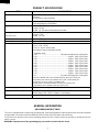
ITEM DESCRIPTION
Power Requirements 120 Volts / 14 Amperes / 1600 W
60 Hertz
Single phase, 3 wire grounded
Power Output 1100 watts (IEC TEST PROCEDURE)
Operating frequency of 2450MHz
Case Dimensions Width 29-15/16"
Height 16-3/8"
Depth 16- 1/8" (Not including the door handle)
Cooking Cavity Dimensions Width 21"
Height 8-7/8"
1.6 Cubic Feet Depth 14-7/16"
Hood lamp 2 bulbs, 20W x 2, Incandescent light bulbs
Hood fan Approx. 300 C.F.M.
Control Complement Touch Control System
Clock ( 1:00 - 12:59 )
Timer (0 - 99 min. 99 seconds)
Microwave Power for Variable Cooking
Repetition Rate;
P-HI .................................................. Full power throughout the cooking time
P-90 .................................................................... approx. 90% of Full Power
P-80 ....................................................................approx. 80% of Full Power
P-70 ....................................................................approx. 70% of Full Power
P-60 ....................................................................approx. 60% of Full Power
P-50 ....................................................................approx. 50% of Full Power
P-40 ....................................................................approx. 40% of Full Power
P-30 ....................................................................approx. 30% of Full Power
P-20 ....................................................................approx. 20% of Full Power
P-10 ....................................................................approx. 10% of Full Power
P-0 ...................................................... No power throughout the cooking time
TOUCH SCREEN, ONE TOUCH SENSOR pads, Beverage Center pad
Keep Warm pad, Defrost pad, MINUTE PLUS pad, STOP/CLEAR pad
START pad, 6 x 6 NO GUESS COOKING pads
MORE FROM YOUR MICROWAVE 6 x 6 pad, Fan Options pad
Light Options pad, Turntable On/Off pad, Set Up pad
Oven Cavity Light 20W Incandescent light bulb
Safety Standard UL Listed FCC Authorized
DHHS Rules, CFR, Title 21, Chapter 1, Subchapter J
Weight Approx. 46 lbs.
PRODUCT SPECIFICATION
GENERAL INFORMATION
GROUNDING INSTRUCTIONS
This oven is equipped with a three prong grounding plug. It must be plugged into a wall receptacle that is properly installed
and grounded in accordance with the National Electrical Code and local codes and ordinances.
In the event of an electrical short circuit, grounding reduces the risk of electric shock by providing an escape wire for the
electric current.
WARNING: Improper use of the grounding plug can result in a risk of electric shock.

5
PMOR30B
PMOR30R
PMOR30S
Electrical Requirements
The oven is equipped with a 3-prong grounding plug. DO NOT UNDER ANY CIRCUMSTANCES CUT OR REMOVE THE
GROUNDING PIN FROM THE PLUG.
The power supply cord and plug must be connected to a separate 120 Volt AC, 60 Hz, 15 Amp. or more dedicated line, using
a grounded receptacle. The receptacle should be located inside the cabinet directly above the Microwave Oven/Hood
system mounting location.
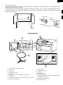
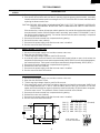
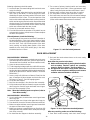
OVEN DIAGRAM
1. Oven door with see-through window.
2. Door hinges.
3. Stirrer cover.
4. Turntable motor shaft.
5. Oven lamp.
It will light when oven is operating or door is open.
6. Door latches.
The oven will not operate unless the door is securely closed.
7. Auto-Touch control panel.
8. Touch Screen.
9. Ventilation openings.
10.Light Cover.
11.Grease filters.
12.Removable turntable.
The turntable will rotate clockwise or counterclockwise.
Only remove for cleaning.
13.Removable turntable support.
14. Power supply cord
3-Pronged Plug
Grounded
Receptacle Box
Grounding Pin
3-Pronged Receptacle
10
11
12
14
9
13
8
7
6
9
3
4
5
1
2

6
PMOR30B
PMOR30R
PMOR30S
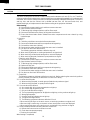
OPERATION
DESCRIPTION OF OPERATING SEQUENCE
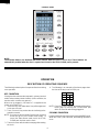
CONTROL PANEL
The following is a description of component functions during
oven operation.
OFF CONDITION
Closing the door activates the stop switch, primary interlock
switch and secondary interlock switch. (In this condition, the
monitor switch contacts are opened.)
When oven is plugged in, 120 volts A.C. is supplied to the
control unit (Figure O-1).
1. "Set clock" key and "Video demo" key will be appeared
on the touch screen.
2. Touch "Set clock" key and set the clock referring to the
operation manual.
NOTE: If no keys are touched within 30 seconds, the touch
screen will go on to the Video Demo mode. To
cancel the Video Demo mode, touch the STOP/
CLEAR pad. And then set the clock.
3. The touch screen will show the home page after setting
the clock.
4. The following is an example of the Home page when
the time of the day is set to 12:30 p.m..
NOTE: Even if the clock is not set, the display will show the
Home page by touching the STOP/CLEAR pad
within 30 seconds after being plugged in.
COOKING CONDITION
Program desired cooking time touching the NUMBER pads.
When the START pad is touched, the following operations
occur:
Minute
Plus +
Kitchen
Timer
12 : 30 PM
123
456
78
0
9
NOTE:
The directed features are disabled after three minutes when the oven is not in use. These features are
automatically enabled when the door is opened and closed or the STOP/ CLEAR pad is pressed.

7
PMOR30B
PMOR30R
PMOR30S
1. The contacts of relays are closed and components
connected to the relays are turned on as follows.
(For details, refer to Figure O-2)
RELAY CONNECTED COMPONENTS
RY1 Oven lamp / Fan motor / Stirrer motor
RY2 Turntable motor
RY3, RY4 Hood fan motor
2. 120 volts A.C. is supplied to the inverter unit and is
converted in order to power of the magnetron by the high
frequency switching power circuit. The frequency is
approx. 27
_
40 KHz.
3. The filament winding voltage of H.V. transformer heats
the magnetron filament and the H.V. winding gives a
high voltage approx. 2 KV to activaite a voltage doubler
circuit. Then approx. 4KV peak voltage power is supplied
to the magnetron cathode terminal.
4. The microwave energy produced by the magnetron is
channelled through the waveguide into the cavity feed-
box, and then into the cavity where the food is placed to
be cooked.
5. Upon completion of the cooking time, the inverter unit,
oven lamp, etc. are turned off, and the generation of
microwave energy is stopped. The oven will revert to the
OFF condition.
6.
When the door is opened during a cook cycle, the monitor
switch, stop switch, secondary interlock switch and primary
interlock switch are activated with the following results.
The circuits to the stirrer motor, the cooling fan motor, the
turntable motor, and the inverter unit are de-energized,
and the touch screen displays the time still remaining in
the cook cycle when the door was opened.
7. The monitor switch is electrically monitoring the operation
of the secondary interlock switch and primary interlock
switch and is mechanically associated with the door so
that it will function in the following sequence.
(1) When the door opens from a closed position, the
primary interlock switch and secondary interlock
switch open their contacts, and then the monitor
switch contacts close. And contacts of the relay
(RY1) remain closed.
(2) When the door is closed from the open position, the
monitor switch contacts first open and the stop
switch contacts open, and then the contacts of the
secondary interlock switch and primary interlock
switch close. And contacts of the relay (RY1) open.
If the secondary interlock switch and primary interlock
switch fail with their contacts closed when the door is
opened, the closing of the monitor switch contacts will form
a short circuit through the monitor fuse, secondary interlock
switch, primary interlock switch and relay (RY1) causing the
monitor fuse to blow.
VARIABLE COOKING
When Variable Cooking Power is programmed, the 120
volts A.C. is supplied to the inverter unit which is operated
by the control unit. Microwave power operation is as follows:
The oven can be set for any of 11 power levels: 0% to
100%(HIGH). The variable cooking power less than 40% is
programmed at the ratio of ON time and OFF time within 32
sec./ cycle time base.
CONNECTION BETWEEN POWER SETTING AND ON/
OFF TIME OF INVERTER UNIT.
OUTPUT POWER SETTING ON TIME OFF TIME
Power 100%
Power 90%
Power 80%
Power 70% Continue operation
Power 60%
Power 50%
Power 40% 26 sec. 6 sec.
Power 30% 22 sec. 10 sec.
Power 20% 16 sec. 16 sec.
Power 10% 8 sec. 24 sec.
Power 0% 0 sec. 32 sec.
Note: The ON/OFF time ratio does not correspond with
the percentage of microwave power, because
approx. 3 seconds are needed for heating of the
magnetron filament.
SENSOR COOKING CONDITION
Using the Sensor cooking function (See sensor cooking
menus), the food is cooked without figuring time, power level
or quantity. When the oven senses enough steam from the
food, it relays the information to its microprocessor which will
calculate the remaining cooking time and power level needed
for best results. When the food is cooked, water vapor is
developed. The sensor “senses” the vapor and its resistance
increases gradually. When the resistance reaches the value
set according to the menu, supplementary cooking is started.
The time of supplementary cooking is determined by experi-
ment with each food category and input into the LSI.
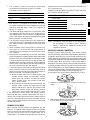
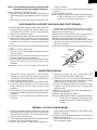
An example of how sensor works: (BAKED POTATOES)
1. Potatoes at room temperature. Vapor is emitted very
slowly.
2. Heat Potatoes. Moisture and humidity is emitted rapidly.
You can smell the aroma as it cooks.
MICROWAVE
MICROWAVE
AH SENSOR

8
PMOR30B
PMOR30R
PMOR30S
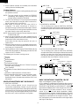
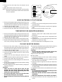
2. HORIZONTAL VENTING
The air handing is the same as VERTICAL VENTING
except that the final air discharge is directed horizontally
out from the top rear of the oven into the customer's vent
system.
: AIR FLOW
3. Sensor detects moisture and humidity and calculates
cooking time and variable power.
Cooking Sequence.
1. Operate the oven in sensor cooking mode by referring to
the operation manual.
NOTE: The oven should not be operated on SENSOR
immediately after plugging in the unit. Wait two
minutes before cooking on SENSOR.
2. The coil of shut-off relay (RY-1) is energized, the turntable
motor, oven lamp and cooling fan motor are turned on,
but the inverter unit is not turned on.
3. After about 32 seconds, the cook relay (RY-2) is
energized. The power transformer is turned on,
microwave energy is produced and first stage is started.
The 32 seconds is the cooling time required to remove
any vapor from the oven cavity and sensor.
NOTE: During this first stage, do not open the door or touch
STOP/CLEAR pad.
4. When the sensor detects the vapor emitted from the
food, the display switches over to the remaining cooking
time and the timer counts down to zero.
At this time, the door may be opened to stir, turn, or
season food.
5. When the timer reaches zero, an audible signal sounds.
The shut-off relay is de-energized and the inverter unit,
oven lamp, etc. are turned off.
6. Opening the door or touching the STOP/CLEAR pad, the
time of day will reappear on the display and the oven will
revert to an OFF condition.
The following are the sensor cooking menus.
Reheat
Popcorn
Baked potatoes
Vegetables
Ground beef or Meat
Boneless Chicken Breast, Bone-in Chicken Pieces and
Ground Poultry of Poultry
Fish / Seafood
Vegetables, Entrees, Main Dishes and Snacks of Frozen
food
White Rice and Brown Rice of Pasta Grains
Frozen breakfast food, Meal in cup, Hot dogs in buns,
Soup, Frozen sandwich, Stuffed Acorn Squash,
Ratatouille, Bacon, Microwave pizza of More From Your
Microwave.
VENTILATION METHODS HOT AIR EXHAUST
1. VERTICAL VENTING
For this venting method, hot air rising from the
conventional range below is drawn in by the hood fan
motor through the grease filters at the right and left sides
of the base cover, up through the right and left sides of
the oven cavity, then discharged vertically at rear center
top of the oven, into the customer's vent system.
3. RE-CIRCULATION (INSIDE VENTING)
The air handing is the same as VERTICAL VENTING
except that the final air discharge is directed horizontally
through the upper front of the oven into the kitchen. In
this case, the accessory charcoal filter RK-230 must be
provided to filter the air before it leaves the oven.
: AIR FLOW
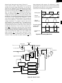
BASIC OPERATION OF INVERTER CIRCUIT
Basic circuit diagram is shown Figure A-1.
AC line voltage is rectified and converted to direct-current
voltage (DC. Voltage). By switching the power transistor Q1
ON and OFF, High frequency current (about 27 - 40 KHz) is
generated controlled by the IC of the inverter unit. OFF-time
of the transistor Q1 is nearly constant. That is, on-time is
varied. It is a kind of Pulse Width Modulation (PWM).
Because off-time is constant, switching frequency is varied
in response to the length of on-time and output power of
magnetron is proportional to the length of on-time. There-
fore, the frequency of inverter becomes low for high output
and high for low output.
GREASE
FILTER
HOOD FAN MOTOR
TO DUCT
TO DUCT
HOOD
INTAKE
DUCT
HOOD
INTAKE
DUCT
HOOD FAN MOTOR
GREASE
FILTER
TO DUCT
HOOD
INTAKE
DUCT
HOOD EXHAUST
LOUVER
HOOD FAN MOTOR
CHARCOAL
FILTER
: AIR FLOW

9
PMOR30B
PMOR30R
PMOR30S
Wave-form of main parts are shown in Figure A-2.
During off-time, flyback voltage appears on the primary
winding of the high voltage transformer. The off-time de-
pends on the inductance of the transformer and capaci-
tance of the resonant capacitor C3. Synchronous circuit
generates the timing signal by detecting the flyback volt-
age. The power transistor Q1 is periodically switched on
when the collector voltage returns to zero (0) volt. High
voltage (about 2 KV) appears on secondary winding of the
transformer. The full-wave voltage doubler circuit increase
to about 4 KV and is applied to the magnetron. The effi-
ciency of the inverter unit itself is approx. 93%, and equal to
that of current efficiency. Ferrite core is used for the high
voltage transformer. It is superior to silicon steel core at
high frequency, low magnetic loss. The power level is
determined by the touch control board, and the PWM data
corresponding to the level is set to the IC of the inverter unit
through the control lines. The IC controls on-time of tran-
sistor Q1 by comparing the average value of the primary
current with the magnitude of the power level data. The IC
has the protection circuit which detects over-current of the
main circuit and the high voltage circuit, over-voltage of the
power transistor Q1 and AC power interruption. When
abnormal phenomenon is detected, the IC pauses on the
moment in order to protect the power transistor Q1 from
Figure A-1. Basic Circuit
being destroyed. After approx. 60 millisecond, it starts
generating the driving signal from the minimum pulse width
and expands the length of on-time slowly until the current
of the main circuit reaches the target level.
Figure A-2. Switching Wave-form
Driving signal
Collector
current of Q1
Collector
voltage of Q1
Secondary voltage
of high voltage
transformer
Synchronous
signal
A
A
Choke coil
Bridge diode
High voltage
transformer
Magnetron
R
103
R
102
C11
C12
D11
D12
C3
C2
Power
transistor
Q1
AC 120V / 60 Hz
+ V
IC
Driving
Circuit
Synchronous Circuit
Voltage Detector
Overcurrent and
Overvoltage Detector
Average Current
Synchronous
Signal for AC.
Output Control
Signal

10
PMOR30B
PMOR30R
PMOR30S
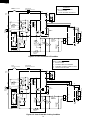
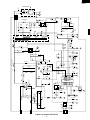
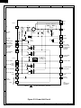
SCHEMATIC
NOTE: CONDITION OF OVEN
1. DOOR CLOSED
2. COOKING TIME PROGRAMMED
3. VARIABLE COOKING CONTROL "HIGH"
4. "START" PAD TOUCHED
Figure O-2. Oven Schematic-Cooking Condition
Figure O-1. Oven Schematic-Off Condition
SCHEMATIC
NOTE: CONDITION OF OVEN
1. DOOR CLOSED
2. CLOCK APPEARS ON DISPLAY
MAGNETRON
TEMPERATURE FUSE
FUSE
20A
TURNTABLE
MOTOR
FAN
MOTOR
STIRRER
MOTOR
MAGNETRON
OVEN LAMP
MONITOR
SWITCH
BLKWHT
INVERTER UNIT
COM.
CONTROL UNIT
GND
GRN
HOOD
MOTOR
B7
B5
B3
B1
Low
High
A1 A3 B9 A5 A7 N.O.
E1
F1
F2
F3
H1
E2
STOP
SWITCH
SECONDARY
INTERLOCK
SWITCH
PRIMARY
INTERLOCK
SWITCH
120 V AC.
60 Hz
HOOD
LAMP
HL HL
RY2 RY1
FM
STM
TTM
HOOD FAN
THERMAL
CUT OUT
HOOD
CAPACITOR
RY3
RY4
N.C.
H2
H3
AC3
A3 A1
FA
F
FFA
M
OVEN
THERMAL CUT-OUT
SSR
OL
AH SENSOR
MAGNETRON
TEMPERATURE FUSE
FUSE
20A
TURNTABLE
MOTOR
FAN
MOTOR
STIRRER
MOTOR
MAGNETRON
OVEN LAMP
MONITOR
SWITCH
BLKWHT
INVERTER UNIT
COM.
CONTROL UNIT
GND
GRN
HOOD
MOTOR
B7
B5
B3
B1
Low
High
A1 A3 B9 A5 A7 N.O.
E1
F1
F2
F3
H1
E2
STOP
SWITCH
AH SENSOR
SECONDARY
INTERLOCK
SWITCH
PRIMARY
INTERLOCK
SWITCH
120 V AC.
60 Hz
HOOD
LAMP
HL HL
RY2 RY1
FM
STM
TTM
HOOD FAN
THERMAL
CUT OUT
HOOD
CAPACITOR
RY3
RY4
N.C.
H2
H3
AC3
A3 A1
FA
F
FFA
M
OVEN
THERMAL CUT-OUT
SSR
OL

11
PMOR30B
PMOR30R
PMOR30S
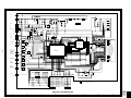
Figure O-3. Inverter Unit Circuit
M
AC3
PWM
MCK
VS
MCK
(CN-A)
VS
(CN-A)
CN-A
OSC
OSC
EN
INT
PA
GND
Q50
AGND
VP0
VCC
OUT
VS
VP2
4.7K
39K
VP1
IA
1
1
1
9
10
18
2
2
3
3
4
MAGNETRON
T1
P1
P2
H2
S2
M2
M1
Q70
VC
VC
S1
H1
D11
D16
D50
D12
0.3µ / 580V
C3
0.03µ
2800V
C11
0.06µ
3100V
C12
1000p/ 50V
C21
VRS3
L2
Q1
120M
(H.V.RESISTOR)
R11
100
1
R103
PD2
D17
ZD70
D1
RBV-2506
39K
R2
100µ / 35V
0.9µ / 200V
- +
C35
1000p / 50V
C61
C2
(J2)
R101
2.2/ 1W
R102
D100
2.2/ 1W
VRS2
47K
1.2KF
4.7K
1M
R20
R35
R62
1.8K
R44
36K
1/2W
R43
33K
1/2W
R42
R55
4.7K
R5
CF1
8MHZ
1.3K/ 5W
1/ 2W 33K
R31
R73
(R72)
D22
D23
D32
D20
h
fe
g
D21
VR1
330
0.01µ/16V
C20
0.01µ/50V
2.2KF
R54
5.6KF
C50
100p/50V
C4
ZD33ZD32
R61
300F
R50
(ZD50)
ZD40
10K
R56
100K
R71
1.5K
R22
120K
R63
R63
4.7K
R30
1.2K
1/2W
R34
4.7K
R6
1.3KF
R51
10K
R40
47
R70
Q4
Q3
Q2
10K
R4
R25 TH2
ZD30
ZD31
D30
PD1
PH1
BF20
IC1 LR38166
(IZA406DR)
10µ / 50V
- +
C62
39K
R24
1µ / 50V
- +
C24
C40
18K
R21
430
R45
220p / 50V
C41
100p / 50V
1µ / 50V
- +
C31
1000p / 50V
C30
F
FA
2
4
3
0.1µ/ 25V
C70
VR
VC
VE
Q51
1
4
2
3
PD3

12
PMOR30B
PMOR30R
PMOR30S
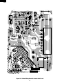
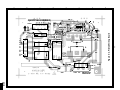
Figure O-4. Printed Wiring Board for Inverter Unit Circuit
3
FA930DR
R42
E
C
G
E
E
M
E
EB
E
+
+
R43
J6
M1
M2
ZD40
C41
J3
Q3
Q2
Q4
C51
R56
R71
Q70
R71
C70
CN-A
Q51
C4
R34
R25
R6
IC1
13
R5
TH2
CT1
AC3
R20
D22
D23
D20
D21
ZD31
J1
C31
CF1
VR1
VRS2
L2
BLUE
RED
R44
R40
C35
R31
D50
ZD32
ZD33
PD2
PD3
D100
EARTH
CMK-P3X
R
94V - 0
D70
R103
F
FA
FA
F
D11
HS2
VRS3
P1
P2
R2
R45
S2
S1
PH1
D1
Q1
VRS4
ZD70
R70
J8
J5
C21
C50
C50
R22
R50
D16
J11
ZD30
R30
R54
R55
TH1
R24
ZD50
R53
C62
PD1
C24
R4
J2
D32
R51
R62
D30
C30
R63
C61
R61
R35
Q50
R21
10
1
9
18
J4
HS1
R11
D12
H2
J10
0.006µF 0.003µF
C12
C11
H1
J7
J9
SOLDER
WR
DANGER H.V.
R101
R102
R72
R73
C3
C2
+
+

13
PMOR30B
PMOR30R
PMOR30S
DESCRIPTION AND FUNCTION OF COMPONENTS
DOOR OPEN MECHANISM
The door is opened by pulling the door handle, refer to the
Figure D-1.
LOCK SWITCH AND MONITOR SWITCH FOR
PROPER OPERATION. (REFER TO CHAP-
TER "TEST PROCEDURE").
NOTE: MONITOR FUSE AND SWITCH ARE REPLACED
AS AN ASSEMBLY
TEMPERATURE FUSE (MG)
The temperature fuse located near the waveguide is
designed to prevent damage to the magnetron if an over
heated condition develops in the tube due to cooling fan
failure, obstructed air guide, dirty or blocked air intake, etc.
Under normal operation, the temperature fuse remains
closed. However, the temperature fuse will open at 302½F
(150½C) causing the oven to shut down.
THERMAL CUT-OUT (HOOD )
This thermal cut-out located on the right base plate. It is
designed to automatically turn on the hood fan motor
whenever the hot air rising from the conventional range
below causes the temperature at the thermal cut-out to rise
to 140½F (60½C) or higher, thus removing this hot air from
around microwave oven. When the temperature around the
thermal cut-out drops to 113½F (45½C) or lower, the thermal
cut-out shuts off the hood fan motor.
THERMAL CUT-OUT (OVEN )
This thermal cut-out is located on the top of the oven cavity.
It is designed to prevent damage to the oven unit if the food
in the oven catches fire due to overheating produced by
improper setting of cooking time or failure of control unit.
Under normal operation, the thermal cut-out remains closed.
However, the thermal cut-out will open at 293½F (145½C)
causing the oven to shut down.
TURNTABLE MOTOR
The turntable motor rotates the turntable located on the
bottom of the oven cavity, so that the foods on the turntable
cook evenly during cooking. Turntable will turn in either
direction. The turntable motor can be turned off by touching
TURNTABLE ON/OFF pad.
COOLING FAN MOTOR
The cooling fan motor drives a blade which draws external
cool air. This cool air is directed through the air vanes
surrounding the magnetron and cools the magnetron. This air
is channelled through the oven cavity to remove steam and
vapors given off from the heating foods. It is then exhausted
through the exhausting air vents at the oven cavity.
HOOD
FAN MOTOR
The hood fan motor is a two-speed, single-phase, double
pole induction type, requiring a hood fan capacitor. It is
located outside the upper rear part of the oven cavity, is to
remove, from around the oven, hot air rising from the
conventional electric or gas range over which it is installed.
This air is then expelled either vertically or horizontally
through the customer supplied duct system, or discharged
back into the kitchen.
Figure D-1. Door Open Mechanism
STOP, PRIMARY INTERLOCK AND SECONDARY
INTERLOCK SWITCHES
The secondary interlock switch is mounted in the lower
position of the latch hook and the stop switch is mounted in
the upper position of the latch hook. The primary interlock
switch is also in the upper position of the latch hook. They
are activated by the latch heads on the door. When the door
is opened, the switches interrupt the circuit to all compo-
nents. A cook cycle cannot take place until the door is firmly
closed thereby activating both interlock switches.
MONITOR SWITCH
The monitor switch is activated (the contacts opened) by the
latch head on the door while the door is closed. The switch
is intended to render the oven inoperative by means of
blowing the monitor fuse when the contacts of the primary
interlock switch and secondary interlock switch fail to open
when the door is opened.
Functions:
1. When the door is opened, the monitor switch contact
close (to the ON condition) due to their being normally
closed. At this time the primary interlock switch and
secondary interlock switch are in the OFF condition
(contacts open) due to their being normally open contact
switches. And the contacts of relay (RY1) are in the ON
condition (contacts close).
2. As the door goes to a closed position, the monitor switch
contacts are first opened and the stop switch contacts
close, and then the primary interlock switch and the
secondary interlock switch contacts close. (On opening
the door, each of these switches operate inversely.)
3. If the door is opened, and the primary interlock switch
and secondary interlock switch contacts fail to open, the
monitor fuse blows simultaneously with closing of the
monitor switch contacts.
CAUTION: BEFORE REPLACING A BLOWN MONITOR
FUSE TEST THE STOP SWITCH, PRIMARY
INTERLOCK SWITCH, SECONDARY INTER-
Secondary
Interlock
Switch
Monitor
Switch
Stop
Switch
Monitor
Fuse
Primary
Interlock
Switch
Latch
Hook
Door
Latch
Heads

14
PMOR30B
PMOR30R
PMOR30S
STIRRER MOTOR
The stirrer motor drives the stirrer fan to stir the microwave
radiation from the waveguide.
HOOD LAMP
The hood lamps are mounted at the hood lamp angle on the
base cover. The hood lamps can be turned off and on by
touching the Light Options pad. And also the brightness can
be varied to high or low by touching the Light Options pad.
TROUBLESHOOTING GUIDE
Never touch any part in the circuit with your hand or an uninsulated tool while the power supply is connected.
When troubleshooting the microwave oven, it is helpful to follow the Sequence of Operation in performing the checks. Many
of the possible causes of trouble will require that a specific test be performed. These tests are given a procedure letter which
will be found in the "Test Procedure "section.
IMPORTANT: If the oven becomes inoperative because of a blown monitor fuse, check the monitor switch, relay (RY1)
primary interlock switch and secondary interlock switch before replacing the monitor fuse. If monitor fuse
is replaced, the monitor switch must also be replaced. Use part FFS-BA016/KIT as an assembly.
IMPORTANT: Whenever troubleshooting is performed with the power supply cord disconnected. It may in, some cases,
be necessary to connect the power supply cord after the outer case has been removed, in this event,
1. Disconnect the power supply cord, and then remove outer case.
2. Open the door and block it open.
3. Discharge high voltage capacitor.
4. Disconnect the leads to the primary of the power transformer.
5. Ensure that the leads remain isolated from other components and oven chassis by using insulation tape.
6. After that procedure, reconnect the power supply cord.
When the testing is completed
1. Disconnect the power supply cord, and then remove outer case.
2. Open the door and block it open.
3. Discharge high voltage capacitor.
4. Reconnect all leads removed from components during testing.
5. Reinstall the outer case (cabinet).
6. Reconnect the power supply cord after the outer case is installed.
7. Run the oven and check all functions.

15
PMOR30B
PMOR30R
PMOR30S
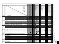
CK = Check / RE = Replace
POSSIBLE CASE AND
DEFECTIVE PARTS
PROBLEM
TEST PROCEDURE
CONDITION
OFF
CONDITION
IDLE
CONDITION
MICROWAVE
COOKING
CONDITION
SENSOR
COOKING
CONDITION
Home fuse blows when power cord is plugged into wall receptacle.
Monitor fuse blows when power cord is plugged into wall receptacle.
Display does not illuminate when power cord is first plugged into wall receptacle.
Display does not operate properly when STOP/CLEAR key is touched. (The
time of day should appear on the display with beep sound during normal
condition.)
Oven lamp does not light with door is opened.
Hood fan motor operates when power cord is first plugged into wall receptacle.
Temperature of oven base seems more than 140˚F (60˚C) because of operation
of the range below. But hood fan motor does not turn on automatically.
(Normally, food fan motor should be operating at low speed.)
Hood lights do not turn on when Light Options pad is pressed.
Hood fan motor does not rotate at all with touched Fan Options pad.
Speed of the hood fan motor does not change when the Fan Options pad is
touched for this function.
Oven lamp does not light in cook cycle. (But it does light when door is opened.)
Fan motor does not operate. (Oven lamp and turntable motor operate.)
Turntable motor does not operate (Oven lamp lights and fan motor operates.)
Oven does not go into cook cycle when START pad is touched
Oven seems to be operating but little or no heat is produced in oven load.
(Food incompletely cooked or not cooked at all at end of cook cycle.)
Oven goes into a cook cycle but extremely uneven heating is produced in
oven load (food).
Variable cooking does not operate properly except Cooking Power 100% mode.
Function of COMPU DEFROST does not operate properly.
Stirrer motor does not operate. (Other parts operate.)
Oven goes into COMPU DEFROST but food is not defrosted well.
The oven Stops and "ERROR" is displayed or does not end during Sensor
Cooking condition. (Oven does not shut off after a cup of water is boiling by
Sensor Cooking.)
Oven stops at 32 seconds after starting.
CK LOW VOLTAGE
CK NO POWER AT OUTLET
RE SHORTED IN POWER CORD
CK OPENED OR SHORTED WIRING
CK HOOD MOTOR CAPACITOR
RE HOOD LAMP OR SOCKET
CK TURNTABLE OFF CONDITION
RE STIRRER MOTOR
RE TURNTABLE MOTOR
RE FAN MOTOR
RE OVEN LAMP OR SOCKET
O AH SENSOR
N FOIL PATTERN ON P.W.B.
M COMPU DEFROST
L RELAY (RY-4)
L RELAY (RY-3)
L RELAY (RY-2)
L RELAY (RY-1)
K KEY UNIT
J CONTROL UNIT
I HOOD FAN MOTOR
H HOOD THERMAL CUT-OUT
G MONITOR FUSE
F MONITOR SWITCH
E
STOP SWITCH
D PRIMAARY INTERLOCK SWITCH
D SECONDARY INTERLOCK SWITCH
C
TEMPERATURE FUSE OR THERMAL CUT-OUT
B INVERTER UNIT
A MAGNETRON

16
PMOR30B
PMOR30R
PMOR30S
B INVERTER UNIT TEST
TEST PROCEDURES
PROCEDURE
LETTER
COMPONENT TEST
1. Disconnect the power supply cord, and then remove outer case.
2. Open the door and block it open.
3. To discharge high voltage capacitor, wait for 60 seconds.
4. To test for an open filament, isolate the magnetron from the high voltage circuit. A continuity check
across the magnetron filament leads should indicate less than 1 ohm.
5. To test for a shorted magnetron, connect the ohmmeter leads between the magnetron filament leads
and chassis ground. This test should indicate an infinite resistance. If there is little or no resistance
the magnetron is grounded and must be replaced.
6. Reconnect all leads removed from components during testing.
7. Reinstall the outer case (cabinet).
8. Reconnect the power supply cord after the outer case is installed.
9. Run the oven and check all functions.
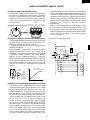
MICROWAVE OUTPUT POWER
The following test procedure should be carried out with the microwave oven in a fully assembled
condition (outer case fitted).
HIGH VOLTAGES ARE PRESENT DURING THE COOK CYCLE, SO EXTREME CAUTION SHOULD
BE OBSERVED.
Power output of the magnetron can be measured by performing a water temperature rise test. This test
should only be used if above tests do not indicate a faulty magnetron and there is no defect in the following
components or wiring: silicon rectifier, high voltage capacitor and power transformer. This test will require
a 16 ounce (453cc) measuring cup and an accurate mercury thermometer or thermocouple type
temperature tester. For accurate results, the following procedure must be followed carefully:
1. Fill the measuring cup with 16 oz. (453cc) of tap water and measure the temperature of the water with
a thermometer or thermocouple temperature tester. Stir the thermometer or thermocouple through
the water until the temperature stabilizes. Record the temperature of the water.
2. Place the cup of water in the oven. Operate oven at POWER 10(HIGH) selecting more than 60
seconds cook time. Allow the water to heat for 60 seconds, measuring with a stop watch, second hand
of a watch or the digital read-out countdown.
3. Remove the cup from the oven and again measure the temperature, making sure to stir the
thermometer or thermocouple through the water until the maximum temperature is recorded.
4. Subtract the cold water temperature from the hot water temperature. The normal result should be 29.9
to 55.4½F(16.6 to 30.8½C) rise in temperature. If the water temperatures are accurately measured and
tested for the required time period the test results will indicate if the magnetron tube has low power
output (low rise in water temperature) which would extend cooking time or high power output (high
rise in water temperature) which would reduce cooking time. Because cooking time can be adjusted
to compensate for power output, the magnetron tube assembly should be replaced only if the water
temperature rise test indicates a power output well beyond the normal limits. The test is only accurate
if the power supply line voltage is 120 volts and the oven cavity is clean.
A MAGNETRON ASSEMBLY TEST
WARNING: DO NOT TOUCH THE COMPONENTS OF THE INVERTER UNIT WHILE INVERTER
UNIT IS ENERGIZED. IT IS DANGEROUS BECAUSE THIS HAS HIGH VOLTAGE
COMPONENTS.
1. Disconnect the power supply cord, and then remove outer case.
2. Open the door and block it open.
3. To discharge high voltage capacitor, wait for 60 seconds.
4. Isolate the inverter unit electrically.
5. Check the inverter unit by referring the following chart and test procedure.

17
PMOR30B
PMOR30R
PMOR30S
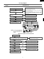
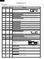
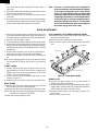
Chart for checking the defective inverter unit
No power at full power output cooking
Varistor VRS2 or/and foil pattern open
on the inverter unit .
High Voltage diode D11 and D12 are
defective.
Magnetron is defective.
H. V. transformer is defective.
Exchange the Inverter unit
Figure B-1 Foil pattern circuit on Inverter Unit
Brown monitor fuse
The secondary interlock switch, primary interlock
switch and the monitor switch are operating properly.
YES
power transistor Q1 is defective.
YES
Exchange the power transistor Q1.
NO
Bridge diode D1 is defective.
YES
Exchange the bridge diode D1.
NO
Varistor VRS3 is defective.
YES
Exchange the varistor VRS3.
NO
H. V. transformer is defective.
YES
Exchange the H. V. transformer.
YES
NO
YES
NO
NO
YES
Varistor VRS2 is defective.
Exchange the defective parts.
When a foil pattern at "e" is broken, insert a jumper
wire at "J2" and solder.
When a foil pattern at "e" and "f" are broken, insert
a coil RCILF2003YAZZ between "g" and "h". (See
Figure B-1.)
Exchange the D11 and D12.
Exchange the magnetron.
Exchange the H. V. transformer
YES
TEST PROCEDURES
PROCEDURE
LETTER
COMPONENT TEST
NO
Check the switches according to
the switch Test Procedure
M
VRS2
L2
BLUE
RED
D1
(J2)
h
f
g
e
D32
NOTE: "e", "f," "g", "h" and "(J2)"
are not indicated on
P.W.B.
NO
Exchange the Inverter unit

18
PMOR30B
PMOR30R
PMOR30S
TEST PROCEDURES
PROCEDURE
LETTER
COMPONENT TEST
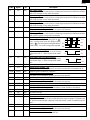
Description of main parts
SYMBOL PART NAME FUNCTION
C11, C12 High voltage capacitor High voltage capacitor for doubler circuit.
C2 Film capacitor To smooth line ripple
C3 Film capacitor Capacitor for resonant
CT1 Current transformer To detect power current
D1 Bridge Diode To rectify full-wave of power supply
D11, D12 High voltage diode Full wave voltage doubler
IC1 Integrated Circuit (IC) Inverter circuit controller
L2 Choke Coil To smooth line ripple
Q1 Transistor Power transistor for switching
Q2, Q3 Transistor To drive transistor Q1 ON-OFF
T1 High voltage transformer assembly High voltage transform for high frequency
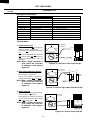
Test procedure
1. Power transistor Q1
Check the transistor Q1 by using ohm-
meter as shown in Figure B-2
If transistor Q1 is defective exchange
Q1.
Check the bridge diode D1, transistor
Q2 and transistor Q3 by using ohm-
meter and replace them if they are
defective.
NOTE: When a digital ohmmeter is
used, reverse the connection
of ohmmeter leads against
Figure B-2.
2. High voltage diode D11 and D12
Check these diodes by using ohmme-
ter as shown in Figure B-2.
If one of the diode is shorted, ex-
change both diodes D11 and D12.
NOTE: When a digital ohmmeter is
used, reverse the connection
of ohmmeter leads against
Figure B-3.
Figure B-3. Check for high voltage diode D11 & D12
3. Bridge diode D1
Check the diode D1 by using ohmme-
ter as shown in Figure B-4.
If the diode D1 is defective, exchange
D1 and power transistor Q1 at same
time (Q1 is defective)
NOTE: When a digital ohmmeter is
used, reverse the connection
of ohmmeter leads against
Figure B-4.
Figure B-4. Check for bridge diode D1.
+
0
∞
20
OK NG
x 1Ω
OK: Normal
NG: Defect
GCE
(G, E)
(C)
Q1
-
UX-F0B
D11
UX-F0BL
D12
Anode
Cathode
+
0
∞
20
OK
NG
x 1Ω
OK: Normal
NG: Defect
-
Yelow
color
White
color
Figure B-2. Check for Power Transistor Q1
+
0
∞
20
OK NG
x 1Ω
OK: Normal
NG: Defect
+
-
D1
-
+
-
and
Page is loading ...
Page is loading ...
Page is loading ...
Page is loading ...
Page is loading ...
Page is loading ...
Page is loading ...
Page is loading ...
Page is loading ...
Page is loading ...
Page is loading ...
Page is loading ...
Page is loading ...
Page is loading ...
Page is loading ...
Page is loading ...
Page is loading ...
Page is loading ...
Page is loading ...
Page is loading ...
Page is loading ...
Page is loading ...
Page is loading ...
Page is loading ...
Page is loading ...
Page is loading ...
-
 1
1
-
 2
2
-
 3
3
-
 4
4
-
 5
5
-
 6
6
-
 7
7
-
 8
8
-
 9
9
-
 10
10
-
 11
11
-
 12
12
-
 13
13
-
 14
14
-
 15
15
-
 16
16
-
 17
17
-
 18
18
-
 19
19
-
 20
20
-
 21
21
-
 22
22
-
 23
23
-
 24
24
-
 25
25
-
 26
26
-
 27
27
-
 28
28
-
 29
29
-
 30
30
-
 31
31
-
 32
32
-
 33
33
-
 34
34
-
 35
35
-
 36
36
-
 37
37
-
 38
38
-
 39
39
-
 40
40
-
 41
41
-
 42
42
-
 43
43
-
 44
44
-
 45
45
-
 46
46


Dacor EK 6714 User manual
- Category
- Microwaves
- Type
- User manual
Ask a question and I''ll find the answer in the document
Finding information in a document is now easier with AI
Related papers
Other documents
-
EUROCOM Extron P/2 DA2xi User manual
-
Sharp R320EQ Owner's manual
-
-
-
-
-
Sharp NP700Z5C-S01US User manual
-
-
Sharp CyberChiller Series User manual
-
Electrolux BLMV169GQB User manual