Page is loading ...

Air Conditioning & Heatin g
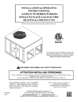
Model TSTATG1152- 2
Digital Thermostat
5+2 Day Programmable
1-Heat & 1-Cool
Heat Pump Compatible
Battery or System Powered
Backlit Digital Display
Fahrenheit or Celsius
Installation Instructions
Tha nk good nes s fo r Go odm an.
TM
Service Filter Indicator

Page 2
Contents Page #
Remove Old Thermostat
Safety Warnings
Preparation
Battery Replacement
Warranty
Test Operation
Troubleshooting
Wire Connections
Jumper Configuration
INSTALLATION INSTRUCTIONS TSTATG1152-2

CAUTION Follow Installation Instructions carefully.
DISCONNECT POWER TO THE HEATER -
AIR CONDITIONER BEFORE REMOVING
THE OLD THERMOSTAT AND INSTALLING
THE NEW THERMOSTAT.
WARNING
Page 3
Safety Warnings
CAUTION
This device complies with Part 15 of the FCC rules.
Operation is subject to the following two conditions:
(1) This device may not cause harmful interference, and (2)
this device must accept any interference received, including
interference that may cause undesired operation.
The two Alkaline “AA” batteries must be replaced at
least once every 12 months to ensure proper
operation. The Low Battery icon (fig. 1) will
appear on the display when it is time to replace
the batteries. If the thermostat is connected to
24v power, the batteries should still be installed, but
are not required.
When is displayed the batteries must be replaced
immediately. The manufacturer cannot be liable for
improper operation of the thermostat if the batteries are
not immediately replaced.
Annual battery replacement is especially critical in
locations subject to freezing temperatures. The
thermostat will be unable to turn on the heating system
if the batteries are exhausted.
P/N TSTATG1152-2
INSTALLATION INSTRUCTIONS
FIG. 1
TSTATG1152-2

Page 4
These tools will be required:
Flat Blade
Screwdriver
Wire cutter
& Stripper
Make sure your Heater/Air Conditioner
is working properly before beginning
installation of the thermostat.
Carefully unpack the thermostat.
Save the screws and instructions.
Turn off the power to the Heating/Air
Conditioning system at the main fuse
panel. Most residential systems have
a separate breaker for disconnecting
power to the furnace.
Proper installation of the thermostat will be
accomplished by following these step
by step instructions. If you are unsure
about any of these steps, call a qualified
technician for assistance.
Preparation
INSTALLATION INSTRUCTIONS TSTATG1152-2

Remove the cover of the old thermostat.
If it does not come off easily check for
screws.
Loosen the screws holding the thermostat
base or subbase to the wall, and lift away.
Disconnect the wires from the old
thermostat. Tape the ends of the wires
as you disconnect them, and mark them
with the letter of the terminal for easy
reconnection to the new thermostat.
Keep the old thermostat for reference
purposes, until your new thermostat is
functioning properly.
Remove & Replace
Old Thermostat
Page 5
INSTALLATION INSTRUCTIONS TSTATG1152-2

Page 6
INSTALLATION INSTRUCTIONS TSTATG1152-2
SET
HEAT
Su
PM
I2:00
:
FIG. 1
Battery Replacement
The batteries are easily accessible from the battery
door located on the bottom front of the thermostat
(fig. 1). To open the battery slot, pull out on the
battery door (fig. 1) and swing down (fig. 2).
Push up on the battery door and snap closed (fig. 4).
FIG. 2
Swing down
FIG. 4
Snap closed
Push up
The batteries must be replaced
immediately when the thermostat
displays the low battery icon (fig.
1). If the thermostat is connected
to 24v power, the batteries should
still be installed. Installing the batteries when
system powered (24VAC) will keep the clock
running in the event of line power interruption.
FIG. 3
Old
batteries
out
New
batteries
in
Remove the old batteries and replace with the new
AA alkaline batteries (fig. 3).
FIG. 1
Battery
Door
Pull out
SET
HEAT
BATTERIES
COOL OFF HEAT
AA
Alkaline

Page 7
Wire Connections
If the terminal designations on your old
thermostat do not match those on the
new thermostat, refer to the chart below
or the wiring diagrams that follow.
Wire from the
old thermostat
terminal marked Function
Install on the
new thermostat
connector marked
CCommon
Y1 or Y Cooling Y
W1, W or H Heating W
G or F Fan G
O/B Rev. Valve O/B
C (optional)
Thermal Insulating Sheet
RC, R, M, Vr, A Power RC*
(Cooling Transformer)
RH, R, M, Vr, A Power RH*
(Heating Transformer)
*The RC and RH terminals have a factory installed jumper to control
single transformer systems. Remove this jumper to control dual
transformer systems.
Wire Slots
INSTALLATION INSTRUCTIONS
A label is provided on the
backplate that prevents drafts
originating inside the wall from
entering the thermostat.
These drafts, left unchecked, may
cause incorrect room temperature
readings.
Please do not remove this label
from the thermostat. Insert the wires
through the slots provided in the label
as shown in Fig. 1.
TSTATG1152-2
C O/B Y W G RC RH
4Z95
MODEL: TSTATG1152-2
97061606
MADE IN CHINA
USE SIZE “AA”
ALKALINE BATTERIES

Page 8
Sample Wiring Diagrams
Gas or Electric Heat
POWER
R
FAN
G
COMPRESSOR
YW
GAS OR
ELECTRIC HEAT
4 Conductor 18 to 22 gauge
unshielded cable from the
thermostat to the equipment.
Common wire is optional in all installations. If a common wire is not used the
thermostat must be powered by two AA alkaline batteries. These batteries
must be replaced (page 6) each year or when the Low Battery indicator is
displayed (page 3).
*
4 Wire, 1 Stage Cooling, 1 Stage Heating
Residential Gas or Electric Heat, Electric Cool, split systems & package units.
For jumper configuration see pages 14 and 15.
Common wire optional*
Factory installed
jumper between
RC and RH
INSTALLATION INSTRUCTIONS TSTATG1152-2
C O/B Y W G RC RH

Sample Wiring Diagrams
Gas or Electric Heat
POWER
O
FAN
Y
REVERSING VALVE
R
G
COMPRESSOR
4 Conductor 18 to 22 gauge
unshielded cable from the
thermostat to the equipment.
Common wire is optional in all installations. If a common wire is not used the
thermostat must be powered by two AA alkaline batteries. These batteries
must be replaced (page 6) each year or when the Low Battery indicator is
displayed (page 3).
*
Common wire optional*
Factory installed
jumper between
RC and RH
INSTALLATION INSTRUCTIONS TSTATG1152-2
C O/B Y W G RC RH
Page 9
4 Wire, 1 Stage Cooling, 1 Stage Heating-Heat Pump with O reversing valve.
Residential Heat Pumps, split systems & package units, with no auxiliary heat.
For jumper configuration see page 16.

Sample Wiring Diagrams
Gas or Electric Heat
POWER
B
FAN
Y
REVERSING VALVE
R
G
COMPRESSOR
4 Conductor 18 to 22 gauge
unshielded cable from the
thermostat to the equipment.
Common wire is optional in all installations. If a common wire is not used the
thermostat must be powered by two AA alkaline batteries. These batteries
must be replaced (page 6) each year or when the Low Battery indicator is
displayed (page 3).
*
Common wire optional*
Factory installed
jumper between
RC and RH
INSTALLATION INSTRUCTIONS TSTATG1152-2
C O/B Y W G RC RH
4 Wire, 1 Stage Cooling, 1 Stage Heating-Heat Pump with B reversing valve.
Residential Heat Pumps, split systems & package units, with no auxiliary heat.
For jumper configuration see page 17.
Page 10

Sample Wiring Diagrams
Gas or Electric Heat
3 Conductor 18 to 22 gauge
unshielded cable from the
thermostat to the equipment.
Common wire is optional in all installations. If a common wire is not used the
thermostat must be powered by two AA alkaline batteries. These batteries
must be replaced (page 6) each year or when the Low Battery indicator is
displayed (page 3).
*
Common wire optional*
Factory installed
jumper between
RC and RH
INSTALLATION INSTRUCTIONS TSTATG1152-2
C O/B Y W G RC RH
Page 11
FAN
POWER
GR
W
GAS OR
ELECTRIC HEAT
3 Wire, 1 Stage Heating
Residential Gas or Electric Heat units with a separately controlled fan.
For jumper configuration see pages 14 and 15.

Sample Wiring Diagrams
Gas or Electric Heat
2 Conductor 18 to 22 gauge
unshielded cable from the
thermostat to the equipment.
Common wire is optional in all installations. If a common wire is not used the
thermostat must be powered by two AA alkaline batteries. These batteries
must be replaced (page 6) each year or when the Low Battery indicator is
displayed (page 3).
*
Common wire optional*
Factory installed
jumper between
RC and RH
INSTALLATION INSTRUCTIONS TSTATG1152-2
C O/B Y W G RC RH
POWER
R
W
GAS OR
ELECTRIC HEAT
Page 12
2 Wire, 1 Stage Gas Heat
Residential Gas or Millivolt units.
For jumper configuration see page 14.

Page 13
Sample Wiring Diagrams
Gas or Electric Heat
Dual Transformer 5 Wire, 1 Stage Cooling, 1 Stage Heating
Residential Gas or Electric Heat, Electric Cool, split systems & package units.
For jumper configuration see pages 14 and 15.
Remove the
factory installed
jumper between
RC and RH 5 Conductor 18 to 22 gauge
unshielded cable from the
thermostat to both sets of
equipment.
COMPRESSOR
YRC
POWER
COOL
Cooling System
FAN
RH
G
GAS OR
ELECTRIC HEAT
W
POWER
HEAT
Heating System
If a common wire is used it must be connected to the furnace common terminal.
If a common wire is not used the thermostat must be powered by two AA alkaline
batteries. These batteries must be replaced (page 6) each year or when the Low
Battery indicator is displayed (page 3).
*
Common wire optional*
INSTALLATION INSTRUCTIONS TSTATG1152-2
C O/B Y W G RC RH

Page 14
Jumper Configuration
*Output active depending on O/B jumper configuration - For normal
operation do not connect to equipment.
OUTPUTS
No Demand With Demand
Cooling Mode
Heating Mode
O/B* Y, G, O/B*
O/B* W, O/B*
Cooling and Gas Heat
Residential Gas or Electric Heat, Electric Cool, split systems & package units.
INSTALLATION INSTRUCTIONS
TSTATG1152-2
1000
JFK
SKD
1000
JFK
SKD
1000
JFK
SKD
471
471
471
471
471
471
471 471
471
471
471
471
471 471
471
471
471
471
471
471
ASDF
NNE ACPJA
P4S220-5
N8 3D4
471 471 471 471
471
471
471
471
471
471
471
471
ASDF
ASDF
471
ASDF
GAS
ELEC
GAS/ELEC
HP
O
B
C
RH
Y
J3J2J1
GAS
GAS
J1
J2
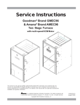
Jumper #1 (J1) should be set for GAS (FAN)
and Jumper #2 (J2) should be set for GAS for
for typical gas furnace heating with electric
cooling. Jumper #3 (J3) is not used.

Jumper Configuration
INSTALLATION INSTRUCTIONS
TSTATG1152-2
1000
JFK
SKD
1000
JFK
SKD
1000
JFK
SKD
471
471
471
471
471
471
471 471
471
471
471
471
471 471
471
471
471
471
471
471
ASDF
NNE ACPJA
P4S220-5
N8 3D4
471 471 471 471
471
471
471
471
471
471
471
471
ASDF
ASDF
471
ASDF
GAS
ELEC
GAS/ELEC
HP
O
B
C
RH
Y
J3J2J1
ELEC
GAS
J1
J2
Cooling and Electric Heat
Residential Electric Heat units with a separately controlled fan.
Page 15
OUTPUTS
No Demand With Demand
Cooling Mode
Heating Mode
O/B* Y, G, O/B*
O/B* W, G, O/B*
*Output active depending on O/B jumper configuration - For normal
operation do not connect to equipment.
Jumper #1 (J1) should be set for ELEC (FAN)
and Jumper #2 (J2) should be set for GAS for
for typical electric heating with electric cooling.
Jumper #3 (J3) is not used.

Jumper Configuration
INSTALLATION INSTRUCTIONS
TSTATG1152-2
1000
JFK
SKD
1000
JFK
SKD
1000
JFK
SKD
471
471
471
471
471
471
471 471
471
471
471
471
471 471
471
471
471
471
471
471
ASDF
NNE ACPJA
P4S220-5
N8 3D4
471 471 471 471
471
471
471
471
471
471
471
471
ASDF
ASDF
471
ASDF
GAS
ELEC
GAS/ELEC
HP
O
B
C
RH
Y
J3J2J1
ELEC
HP
J1
J2
Cooling and Heat Pump-Heat with O reversing valve.
Residential Heat Pumps, split systems & package units, with no auxiliary heat.
Page 16
Y active in Heating
OUTPUTS
No Demand With Demand
Cooling Mode
Heating Mode
OY, G, O
-
Y G,
O
J3
Jumper #1 (J1) should be set for ELEC (FAN),
Jumper #2 (J2) should be set for HP, and
Jumper #3 (J3) should be set for O for typical
heat pump operation. Note: Thermostat does
not have Auxiliary Heat / Emergency Heat
capability.

Jumper Configuration
INSTALLATION INSTRUCTIONS
TSTATG1152-2
1000
JFK
SKD
1000
JFK
SKD
1000
JFK
SKD
471
471
471
471
471
471
471 471
471
471
471
471
471 471
471
471
471
471
471
471
ASDF
NNE ACPJA
P4S220-5
N8 3D4
471 471 471 471
471
471
471
471
471
471
471
471
ASDF
ASDF
471
ASDF
GAS
ELEC
GAS/ELEC
HP
O
B
C
RH
Y
J3J2J1
ELEC
HP
J1
J2 B
J3
Page 17
Y active in Heating
OUTPUTS
No Demand With Demand
Cooling Mode
Heating Mode
Y, G
BY , G, B
-
Cooling and Heat Pump-Heat with B reversing valve.
Residential Heat Pumps, split systems & package units, with no auxiliary heat.
Jumper #1 (J1) should be set for ELEC (FAN),
Jumper #2 (J2) should be set for HP, and
Jumper #3 (J3) should be set for B for typical
heat pump operation. Note: Thermostat does
not have Auxiliary Heat / Emergency Heat
capability.

Test Operation
On the thermostat, slide the Mode Switch
to HEAT. Press the COOLER or WARMER
button until the set temperature is 10 degrees
above room temperature. The HVAC unit
should energize in the heating mode.
Note: You may need to wait up to five minutes
for heating to energize due to the compressor
lockout feature.
On the thermostat, slide the Mode Switch
to COOL. Press the COOLER or WARMER
buttons until the set temperature is 10
degrees below room temperature. The
HVAC unit should energize in the cooling
mode. Note: You may need to wait up to five
minutes for cooling to energize due to the
compressor lockout feature.
Turn on the power to the Heating/Air
Conditioning system.
On the thermostat, slide the Mode Switch to
OFF. Slide the Fan Switch to Fan On. The
fan should turn on and run continuously.
Page 18
INSTALLATION INSTRUCTIONS TSTATG1152-2

Page 19
Trouble Shooting
SYMPTOM: The slide switches on the thermostat
are very difficult to move.
CAUSE: The backplate of the thermostat is
screwed too tightly into a wall that is not
perfectly flat.
REMEDY: Loosen the screws holding the
thermostat into the wall.
INSTALLATION INSTRUCTIONS
SYMPTOM: The Air Conditioning does not
attempt to turn on.
CAUSE: The cooling setpoint is set too
high, the Mode Switch is not set for
Cool, or the batteries are too weak.
REMEDY: Consult the Normal Operation
section in the Owner’s Manual to:
Lower the cooling setpoint.
Correct the Mode Switch position.
Replace the batteries.
SYMPTOM: The fan does not turn on even though
the compressor has energized.
CAUSE: The Fan Switch is not completely in the
On or Auto position.
REMEDY: Slide the Fan Switch firmly into the On
or Auto position.
TSTATG1152-2

Page 20
Trouble Shooting
P/N 88-844
Rev. 1
C
c
F
FOR HOME OR OFFICE USE
Tested to Comply
with FCC Standards
Battery Stat TSTATG1152-2
4Z95
INSTALLATION INSTRUCTIONS
SYMPTOM: The Heating does not attempt
to turn on.
CAUSE: The heating setpoint is set too
high, the Mode Switch is not set for
Heat, or the batteries are too weak.
REMEDY: Consult the Normal Operation
section in the Owner’s Manual to:
Raise the heating setpoint.
Correct the Mode Switch position.
Replace the batteries.
Air Conditioning & Heatin g
Goodman Manufacturing Company, L.P., reserves the right to discontinue, or change at any time,
specifications or designs without notice or without incurring obligations.
Copyright © 2009 • Goodman Manufacturing Company, L.P. • Houston, Texas
TSTATG1152-2
/