Page is loading ...

Installation Instructions
Issue Date April 12, 2006
© 2006 Johnson Controls, Inc.
1
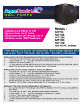
Room Sensor with LCD Display (TMZ1600)
Application
The TMZ is compatible with Unitary (UNT) controller
and Variable Air Volume (VAV) (Revision D or later)
controller and with the VAV for Modular Assembly
(VMA1400 Rev. C00 or later and all VMA1200s). Use
HVAC PRO Release 8.01 or later to configure the
UNT, VAV, and VMA for use with the TMZ. Refer to
the Technical Data section for details.
Part No. 24-8910-7, Rev. C www.johnsoncontrols.com
Code No. LIT-6363110
The TMZ connects to the controller via an 8-pin phone
jack cable assembly that provides Zone Bus, sensor,
and power supply connections.
When the TMZ is used with a compatible
Johnson Controls digital controller, verify proper
system operation using a Zone Terminal Unit (ZTU), a
laptop computer with CBLPRO and HVAC PRO
software, or a Palm™ compatible handheld interface
with VMA Balancing Tool (VBT) software.
Both the ZTU and CBLPRO plug into the 6-pin phone
jack on the bottom of the TMZ to access the Zone bus.
80 mm
(3.2 in.)
inst
OCC
RM
AIR
Light-Emitting
Diode
(LED)
Temporary
Occupancy
Button
Segmented
Display
80 mm
(3.2 in.)
Figure 1: TMZ1600
Installation
Install the TMZ in an accessible location where the
temperature is representative of general room
conditions. Avoid mounting the TMZ near cold or warm
air drafts, radiant heat, or direct sunlight.
IMPORTANT: Prevent any statis electric
discharge to the TMZ1600 Room Sensor. Static
electric discharge can damage the room sensor and
void any warranties.
Note: Do not mount the module on an exterior wall.
Parts Included
The following parts are included with the TMZ:
• TMZ1600 Room Sensor with Liquid Crystal
Display (LCD)
• surface base
• wallbox mount base (wallplate) with cover screw
(for vertical or horizontal 2 x 4 in. wallbox
mounting)
• endcaps (2)
• hollow plastic wall anchors (2)
• No. 8 x 1-1/4 in. slotted pan-head sheet metal
screws (2), for surface base
• No. 6-32 x 1/2 in. flat-head machine screws (2), for
wallplate
Special Tools Needed
For a typical installation, you need the following:
• 1.5 mm (1/16 in.) Allen wrench or stat adjustment
tool
• 1/4 in. flat-blade screwdriver
• 8 mm (5/16 in.) drill bit and drill

Mounting
The TMZ accommodates both surface and 2 x 4 in.
wallbox mounting (horizontal or vertical). To mount the
TMZ, first remove the base.
Removing the Base
To remove the base from the TMZ:
1. Insert a 1.5 mm (1/16 in.) Allen wrench in the hole
located in the top of the TMZ, in the center.
2. Press down gently on the Allen wrench while
carefully pulling the mounting base apart from the
TMZ.
3. Proceed to the Surface Mounting or Wallbox
Mounting section.
Surface Mounting
To mount the TMZ using the surface base:
1. Pull the wiring through the wall.
2. Place the surface base against the wall with the
arrow pointing up, and mark the screw holes using
the base as a template. Use the top and bottom
holes for mounting (
Figure 2).
UP
60.9 mm
(2.40 in.)
surfbase
Do not use this hole when mounting
the surface base. The screw will
interfere with the installation of the
TMZ1600.
Note:
Use these holes for mounting.
4.2 mm
(0.17 in.)
6 mm
(0.24 in.)
8.5 mm
(0.33 in.)
4.2 mm
(0.17 in.)
9.1 mm
(0.36 in.)
4.2 mm
(0.17 in.)
30 mm
(1.18 in.)
7.5 mm
(0.30 in.)
31.7 mm
(1.25 in.)
7.5 mm
(0.30 in.)
8.2 mm (0.32 in.)
Figure 2: Surface Base
3. Drill two 8 mm (5/16 in.) holes at the locations you
marked.
Note: An ACC-INSL-1 surface mounting pad may be
used between the mounting base and the dry wall to
accommodate uneven mounting surfaces or block wall
drafts.
2 Room Sensor with LCD Display (TMZ1600) Installation Instructions

4. Insert the anchors in the drilled holes, pull the
wiring through the surface base, position the
surface base, and drive the screws (
Figure 3).
a
b
cb
B
a
s
e
surfmount
Drywall
Figure 3: Mounting the Surface Base
1. 5. Wire the TMZ (refer to the Wiring section in
this document).
2. 6. Reattach the TMZ to the surface-mount base.
Wallbox Mounting
To mount the TMZ using the wallplate and a standard
2 x 4 in. wallbox:
1. Remove the cover screw from the wallplate
(
Figure 4).
2. Pull the wiring through the wallplate.
3. Position the wallplate so that one of the arrows
points up, and fasten the wallplate to the wallbox
using the screws provided.
Note: An ACC-INSL-0 wallbox mounting pad may be
used between the mounting base and the dry wall to
accommodate uneven mounting surfaces or block wall
drafts.
4. Wire the TMZ (refer to the Wiring section in this
document).
5. Attach the TMZ to the wallplate, and replace and
tighten the cover screw with a 1.5 mm (1/16 in.)
Allen wrench or stat adjustment tool.
3. 6. Install the endcaps provided by snapping them
onto the wallplate.
119 mm
(4.70 in.)
80 mm
(3.15 in.)
wallbse
U
P
UP
Use these holes for
mounting to wallbox.
Cover Screw
(Insert the cover screw
above the other UP arrow
for horizontal mounting.)
Figure 4: Wallplate (Shown Vertical)
Room Sensor with LCD Display (TMZ1600) Installation Instructions 3

Wiring
!
CAUTION: Risk of Property Damage.
Do not run low voltage cable in the same conduit or
wiring troughs with high voltage wires. Running low
and high voltage wires in the same conduit or wiring
troughs may damage the equipment or cause
system malfunction.
Note: All terminals are power limited. Electrical
wiring must conform to local codes and should be
done by certified personnel only.
To connect the TMZ to a UNT, VAV, or VMA
controller, connect an 8-pin phone jack cable
assembly from the 8-pin phone jack on the TMZ
(
Figure 5) to the 8-pin phone jack on the controller.
J1
R2 8
U4
D7
U2
L1
C8
U5
C1 7
C1 6
C9
D6
D4
D5
+
J5
C6
Z1
D9
Q3
Y2
Y1
Q1
D2
Q4
RT1
VR1
J6
Q2
D8
C4
tmzwire
To 8-pin
Phone Jack
on Controller
(30 m [100 ft]
Maximum)
8-pin
Phone
Jack
6-pin
Phone
Jack
To ZTU or Laptop PC via CBLPRO Interface
(30 m [100 ft] Maximum)
Figure 5: TMZ1600 Cable Connections
!
CAUTION: Risk of Property Damage.
Do not insert a 6-pin connector or anything other
than an RJ-45 8-pin connector into the 8-pin jack on
the back of the TMZ1600 Room Sensor to prevent
damaging the phone jack..
Table 1 describes the pinouts for each phone jack on
the TMZ.
Table 1: TMZ Phone Jack Pinouts
8-Pin Phone Jack on
TMZ
6-Pin Phone Jack on
TMZ
Pin Signal Pin Signal
1 Not Used 1 Not Used
2 Not Used 2 Supply: 24 VAC
3 AI1, Zone
Temperature Sensor
3 Supply/Zone Bus
Common
4 AI1, Sensor Common 4 Not Used
5 Supply: 24 VAC 5 Zone Bus
6 Supply/Zone Bus
Common
6 Not Used
7 Not Used
8 Zone Bus
Figure 6 illustrates the cable and phone jack pinouts
used to connect the TMZ to a controller:
Controller Phone Plug
(Tab Notch Up)
TMZ1600 Phone Plug
(Tab Notch Up)
N
o
t
U
s
e
d
N
o
t
U
s
e
d
A
I
1
A
I
C
O
M
S
u
p
p
ly
C
o
m
m
o
n
N
o
t
U
s
e
d
Z
B
+
1
2
3
4
5
6
7
8
1 2 3 4 5 6 7 8
8-Pin Phone Jack
(Tab Notch Down)
cblfab
Terminal 1 is to the
extreme left as you face
the phone jack opening,
tab notch down.
Note: This may not be typical of prefabricated phone
cable. A telephone system cable is wired opposite of the
zone sensor requirements.
Figure 6: Cable and Phone Jack Pinouts
4 Room Sensor with LCD Display (TMZ1600) Installation Instructions

Operation
Basic Operation
The TMZ1600 has five control buttons. Their basic
functions are described in
Table 2.
Table 2: TMZ1600 Button Functions
Button Function
Menu Cycles through the following display options: room air temperature, outdoor air temperature, comfort
setpoint temperature, and fan operation.
In Password mode*, cycles through these additional display options: comfort setpoint temperature access
status, fan access status, Temporary Occupancy duration, heating setpoint temperature, and cooling
setpoint temperature.
Down
Arrow
Displays the comfort setpoint temperature if pushed while room air temperature is displayed.
Lowers the setpoint temperature when setpoint is displayed and blinking.
Toggles fan operation mode between On and Auto when the fan mode is displayed and blinking.
In Password mode*, sets user access to UnLK.
Up Arrow
Displays the comfort setpoint temperature if pushed while room air temperature is displayed.
Raises the setpoint temperature when the setpoint is displayed and blinking.
Toggles fan operation mode between On and Auto when the fan mode is displayed and blinking.
In Password mode*, sets user access to LOCK.
°F/°C Toggles temperature display between degrees Fahrenheit (°F) and degrees Celsius (°C).
Temporary
Occupancy
Toggles the controller between Standby or Unoccupied mode and Temporary Occupancy mode. The Light-
Emitting Diode (LED) above this button lights when Temporary Occupancy mode is active.
* Press and hold the Menu and °F/°C buttons simultaneously for 10 seconds to access Password mode.
LCD Display Symbols
Figure 7 shows the relative size and location of the
LCD Display symbols:
OFF
TMP
UN
-
OCC
SBy
OUT
RM
A
IR
Figure 7: LCD Display Symbols
During power up, the full range of LCD Display
symbols appears for approximately 10 seconds or
more, followed by Err6 if the controller has not started
communication yet. The TMZ repeats this sequence
until the default display (RM AIR) appears.
Table 3 describes the LCD display symbols.
Room Sensor with LCD Display (TMZ1600) Installation Instructions 5

Table 3: LCD Display Symbol Descriptions
Symbol Description
RM AIR Room Air: indicates the room air (zone) temperature is displayed. The room air temperature value is
not adjustable. The LCD defaults to this display if no button is pressed for more than 30 seconds.
OUT AIR Outdoor Air: indicates the outdoor air temperature is displayed. The outdoor air temperature value is
not adjustable.
TMP OCC Temporary Occupancy: indicates controller is in Temporary Occupancy mode.
In Password mode, indicates that Temporary Occupancy duration is displayed.
UNOCC Unoccupied: indicates controller is in Unoccupied mode.
OCC Occupied: indicates controller is in Occupied mode.
SBy Standby: indicates controller is in Standby mode. This is an energy conservation mode of the
controller.
OFF Off: indicates heating and cooling equipment is off (Shutdown mode).
Comfort Setpoint Temperature: indicates the comfort setpoint temperature is displayed (7 to 32°C
[45 to 90°F] maximum range).
In Password mode, indicates comfort setpoint temperature access status (UnLK or LOCK) is
displayed. Comfort setpoint temperature access status can be changed if segmented display is
blinking.
Heating Mode (flame symbol): indicates heating equipment is on.
In Password mode, indicates the heating setpoint temperature is displayed (4.5 to 31.1°C [40 to 89°F]
maximum range). The heating setpoint temperature value is adjustable if the segmented display is
blinking. (Dual setpoint applications only. Field is skipped for single setpoint applications.)
Cooling Mode (snowflake symbol): indicates cooling equipment is on.
In Password mode, indicates the cooling setpoint temperature is displayed (7.8 to 35°C [46 to 95°F]
maximum range). The cooling setpoint temperature value is adjustable if the segmented display is
blinking. (Dual setpoint applications only. Field is skipped for single setpoint applications.)
Fan: indicates fan is on.
In Password mode, indicates fan access status (UnLK or LOCK) is displayed. Fan access status can
be changed if segmented display is blinking.
Fan On: indicates fan is on. Fan status can be changed if segmented display is blinking.
Fan Auto: indicates fan is automatically controlled (turned on or off) by the controller. Fan status can
be changed if segmented display is blinking.
Fan Off: indicates fan is off. Fan status can be changed if segmented display is blinking. Also indicates
that Password mode has been exited.
Note: The user cannot set Fan operation to Off.
If fan is off, the fan symbol does not appear on the room air temperature display.
Degrees Fahrenheit
Degrees Celsius
Password Mode: indicates Password mode is active.
Error: indicates an error is detected. The specific error is identified by an accompanying number
(0 through 6). Refer to
Table 5 for specific error message descriptions.
6 Room Sensor with LCD Display (TMZ1600) Installation Instructions

Room Air Temperature
The room air temperature is the default display for
the TMZ. If no button is pressed for 30 seconds, the
LCD defaults to the room air temperature. Various
symbols appear along the right side and bottom of
the display to indicate the current mode of the
controller and the status of connected equipment
(
Figure 8). Refer to Figure 7 and Table 3 for a
description of these symbols.
OCC
RM
AIR
Symbols appear here
to indicate the current
mode of the controller,
and the status of
connected equipment.
Figure 8: Room Air Temperature Display
Outdoor Air Temperature
To view the outdoor air temperature, press the Menu
button once while the room air temperature is
displayed. OUT AIR appears on the LCD display to
indicate that the outdoor air temperature is
displayed. If the controller is not configured for
outdoor air, this screen does not appear.
Room Sensor with LCD Display (TMZ1600) Installation Instructions 7
Comfort Setpoint Temperature
In the single setpoint application, the comfort
setpoint temperature is the controller common
setpoint.
In the dual setpoint application, the comfort setpoint
temperature is the average of the heating and
cooling setpoint temperatures. Raising or lowering
the comfort setpoint temperature raises or lowers the
occupied heating and cooling setpoint temperatures
by the same number of degrees. When the actual
room temperature falls below the heating setpoint
temperature, or rises above the cooling setpoint
temperature, heating or cooling equipment is
activated. To individually adjust the heating and
cooling setpoints, refer to the Password Mode
section of this document.
Note: Setpoint adjustments only affect the
setpoints for the Occupied mode of operation.
To view or change the current comfort setpoint
temperature:
1. Press the down or up arrow once while the room
air temperature is displayed, or press the Menu
button until the comfort setpoint temperature
appears (
Figure 9).
OCC
Figure 9: Comfort Setpoint Temperature Display
2. Press the down arrow to lower the comfort setpoint
temperature (this will also lower heating and cooling
setpoint temperatures). Press the up arrow to raise
the comfort setpoint temperature (this will raise
heating and cooling setpoint temperatures). The
maximum comfort setpoint temperature range is
7 to 32°C (45 to 90°F). The HVAC PRO program,
however, can set comfort value high limits and low
limits (in the HVAC PRO program, these are called
High Setpoint Limit and Low Setpoint Limit,
respectively) for a TMZ thermostat. The default
range is 18 to 26°C (65 to 78°F).
Note: The comfort setpoint temperature can be
changed only if the segmented display is blinking. If the
segmented display does not blink, refer to the Jumper
Lockout and Password Mode sections of this document.
Fan Operation
The fan operation display indicates the current fan
operation mode (Off, On, or Auto). If the controller is not
configured for fan control, this screen does not display.
To view or change the current fan operation mode:
4. 1. Press the Menu button until the fan operation
display appears (
Figure 10).
Figure 10: Fan Operation Display
5. 2. Press the arrow buttons to toggle between On
and Auto. On indicates that the fan is always on.
Auto indicates that the fan is automatically controlled
(turned on or off) by the controller.
6. If the Auto fan speed is selected, On or Off
appears on the fan operation display to show the fan
status. The fan does not display Auto, but does
operate in automatic mode.

Note:
ote:
Note:
Note:
ote:
Note:
The fan operation mode can be changed
only if the segmented display is blinking. If the
segmented display does not blink, refer to the
Jumper Lockout and Password Mode sections of
this document. Fan operation cannot be changed
when the TMZ is connected to a VAV controller.
N The user can override N2 overrides to the
fan at the TMZ.
Temporary Occupancy
The Temporary Occupancy button toggles between
the current controller mode (Standby or Unoccupied)
and Temporary Occupancy mode. Temporary
Occupancy mode maintains the same comfort
settings as Occupied mode for a predetermined time
period (0-4 hours) called the Temporary Occupancy
duration. The HVAC PRO controller configuration
must be set for 30 minutes or greater to enable a
timed override command. If the Temporary
Occupancy button is pressed again during the
Temporary Occupancy duration, the controller
immediately reverts to the previous mode. For
information on setting the Temporary Occupancy
duration, refer to the Password Mode section of this
document.
The Temporary Occupancy button does not
function if the controller is in Occupied or Off
(Shutdown) mode, if the Temporary Occupancy
feature is not selected in the controller, or if the
Temporary Occupancy duration is set to zero.
Boost mode is not used with the TMZ. The
LED above the Temporary Occupancy button lights
immediately, and TMP OCC appears on the LCD
after several seconds, when Temporary Occupancy
mode is active.
N The Temporary Occupancy Button will not
function if the jumper on the TMZ is set to the locked
position or if the controller password setting is
locked.
Password Mode
Password mode is a discrete mode that allows
comfort setpoint temperature and fan control to be
blocked from user access. The Temporary
Occupancy duration, occupied heating setpoint
temperature, and occupied cooling setpoint
temperature are also set in Password mode. The
occupied heating and cooling setpoint temperatures
are displayed only with dual setpoint applications.
The Password mode menu items can be
changed only if the segmented display is blinking. If the
segmented display does not blink, refer to the Jumper
Lockout section of this document. If no buttons are
pressed for 30 seconds, Password mode is exited
automatically.
To enter Password mode and set the five Password
mode menu items:
1. Press and hold the Menu and °F/°C buttons
simultaneously for approximately 10 seconds until
PASS appears. The comfort setpoint temperature
access status appears (
Figure 11).
Figure 11: Comfort Setpoint Temperature
Access Status
7. 2. Press the arrow buttons to toggle between UnLK
and LOCK. UnLK allows a user to change the
comfort setpoint temperature; LOCK prevents a user
from changing the comfort setpoint temperature.
8. 3. Press the Menu button once. The fan access
status appears (
Figure 12).
Figure 12: Fan Access Status
Note:
Note:
If the controller is not configured for fan control,
this screen is skipped.
When the TMZ is used with the VMA1400
controller, both the comfort setpoint temperatures
access status and the fan access status are reset to
UnLK if the power resets, if communication with the
Zone Bus is lost, or if a download occurs. When the TMZ
(Firmware Rev. AO7 or later) is used with the VAV, UNT,
or VMA1200 controllers and HVAC PRO Release 8.01,
the fan and setpoint temperature access status are
retained at the last condition (LOCK or UnLK) after a
controller reset, TMZ reset, or a power failure. The fan
and setpoint temperature access status are set to UnLK
after a controller download.
4. Press the arrow buttons to toggle between UnLK
and LOCK. UnLK allows a user to control the fan;
LOCK prevents a user from controlling the fan.
8 Room Sensor with LCD Display (TMZ1600) Installation Instructions

9. 5. Press the Menu button once. The
Temporary Occupancy duration appears (
Figure
13
).
TMP
OCC
Figure 13: Temporary Occupancy Duration
6. Use the arrow buttons to set the time value in
1/2-hour increments up to a maximum of
4 hours. This value determines the length of
time that Temporary Occupancy mode is
maintained after the Temporary Occupancy
button is pressed. Setting the Temporary
Occupancy duration to zero prevents user
access to this feature.
10. 7. Press the Menu button once. The heating
setpoint temperature appears (
Figure 14).
OCC
Figure 14: Heating Setpoint Temperature
Note: If the controller is configured for a single
setpoint, this screen is skipped.
8. Use the arrow buttons to adjust the heating
setpoint temperature. The minimum heating
setpoint temperature is 4.5°C (40°F). The
maximum setpoint temperature is one degree
less than the High Setpoint Limit (also known as
comfort value high limit), which is defined with
the HVAC PRO program (the HVAC PRO
program allows a maximum High Setpoint Limit
of 32°C [90°F]; the default limit is 24.6°C [78°F]).
11. 9. Press the Menu button once. The cooling
setpoint temperature appears (
Figure 15).
OCC
Figure 15: Cooling Setpoint Temperature
Note:
Note:
If the controller is configured for a single
setpoint, this screen is skipped.
10. Press the arrow buttons to adjust the cooling
setpoint temperature. The minimum cooling setpoint
temperature is one degree greater than the Low
Setpoint Limit (also known as comfort value low
limit) defined in the HVAC PRO program (the HVAC
PRO program allows a minimum Low Setpoint Limit
of 7°C [45°F]; the default limit is 18°C [65°F]). The
maximum cooling setpoint temperature is 35°C
(95°F).
12. 11. Press the Menu button to cycle through the
Password mode menu items again, or press the
Menu and °F/°C buttons simultaneously to exit
Password mode. OFF appears on the display while
exiting Password mode.
Outdoor Air Setup
To set up the TMZ for outdoor air, do the following:
1. Open the Inputs screen of the HVAC PRO program.
2. To display the outdoor air temperature on the TMZ,
select any unused AI and define the Long Name to
Outdoor Air Temp.
3. Change the Sensor Type field to match the remote
sensor type.
4. Select OK.
13. 5. Connect the outdoor air sensor to the AI
selected for Outdoor Air Temp.
Remote Sensing
To use a remote sensor instead of using the physical
TMZ sensor, do the following:
1. Open the Inputs screen of the HVAC PRO program.
2. Double-click AI1 Zone Temp.
3. In the upper left corner of the Zone Temp screen,
change AI1 to another unused AI (such as AI2). This
moves Zone Temp to the selected AI.
The TMZ displays any AI as Room Air Temp
when the Long Name field is set as Zone Temp.
4. Change the Sensor Type field to match the remote
sensor type.
5. Select OK.
14. 6. Connect the remote sensor to the AI selected for
Zone Temp. The TMZ now displays the remote
sensor value.
Power Failure
When the TMZ is used with a VMA1400 and
experiences a power failure, all set values are not
affected except the comfort setpoint temperature access
status and fan access status. The comfort setpoint
Room Sensor with LCD Display (TMZ1600) Installation Instructions 9

temperature access status and fan access status
always default to UnLK after a power failure. When
the TMZ is used with a VAV, UNT, or VMA1200, all
set values are not affected after a reset or power
failure.
Jumper Lockout
The jumper on J1 of the TMZ (
Figure 16) has two
positions: UnLK and LOCK. If the jumper is set to
UnLK (Pins 1 and 2), the User and Password mode
menu items function normally.
If the jumper is set to LOCK (Pins 2 and 3), the control
functions of the TMZ (including the Temporary
Occupancy button) are disabled. All menu items display
as usual, but none of the settings can be changed.
Note: The default jumper position from the factory is
the UnLK position.
J1
R28
U4
D7
U2
L1
C8
U5
C17
C16
C9
D6
D4
D5
+
J5
C6
Z1
D9
Q3
Y2
Y1
Q1
D2
Q4
VR1
J6
Q2
D8
C4
Pins 1 and 2 Jumpered on J1
(UnLK Position)
jmprdia
RT1
UnLK LOCK
UnLK LOCK
U2
R28
J1
Figure 16: Jumper Block J1 on TMZ1600
Troubleshooting
Table 4: Basic Problems and Solutions
Problem Solution
Some menu items do not
display.
If the controller is not configured for certain features (such as outdoor air temperature or
fan control), the corresponding menu items do not display.
Display does not default to
preferred units (°F or °C).
To change the default temperature units to either degrees Fahrenheit (°F) or degrees
Celsius (°C), use the HVAC PRO program to change the default units in the controller.
Temporary Occupancy
button does not operate.
Verify the controller is not in Occupied or Off mode. Also verify the Temporary Occupancy
feature is enabled in the controller configuration, the Temporary Occupancy duration is not
set for fewer than 30 minutes, and the OCC OVRD time is not overridden by HVAC PRO.
Verify the TMZ jumper setting is in the unlocked position and the controller password setting
is unlocked.
The ZTU reads FAIL or
does not respond when
connected to the 6-pin
phone jack.
Disconnect the ZTU. Press the Menu button on the TMZ so that the room air temperature is
not displayed (any other display is acceptable). Reconnect the ZTU while the room air
temperature is not displayed. The ZTU should function properly, but the room air
temperature display remains blank until the ZTU is disconnected.
The TMZ room air
temperature does not
update while the ZTU is
connected.
The TMZ cannot communicate on the Zone Bus while the ZTU is connected. Disconnect the
ZTU.
Setpoint limits are too
high or too low, or comfort
value adjustment range is
too large or too small, or
the cooling/heating
setpoint ranges are too
small.
In the Define Remote AI Points section of the HVAC PRO Q&A session, select TMZ Digital
Room Sensor. The default low setpoint limit is 18°C (65°F), and the default high setpoint
limit is 26°C (78°F). To change these limits, select Params in the HVAC PRO program.
Select TMZ Setpoint Range parameter. Double-click either High or Low Setpoint Limit.
Change the Value field to the desired setting. Save the file, then download the file to the
controller. Commission the configuration and verify that the High/Low setpoints are correct.
Note: TMZ Firmware Revision A07 and earlier supported narrower setpoint ranges. To take
full advantage of the wider setpoint ranges described in this literature, TMZ Firmware
Revision A08 or later is required along with HVAC PRO Release 8.04 or later.
Continued on next page . . .
10 Room Sensor with LCD Display (TMZ1600) Installation Instructions

Problem (Cont.) Solution
Displayed room
temperature does not
appear to be correct.
Use the HVAC PRO program to verify AI1 (Zone Temp) Sensor Type is set to Resistive
Nickel (R-NI). Also, verify that Zone Temp is located at AI1. If this fails to correct the
problem, the connection to the TMZ may be faulty. Verify that the cable connections are
correct.
Setpoints display
incorrectly.
Check to see if the HVAC PRO program is overriding the Occ Htg Setpt and Occ Clg Setpt
to settings that force the comfort setpoint temperature outside the range defined for the Low
Setpoint Limit and High Setpoint Limit parameters. If so, release the overrides.
Standby BI is not working. Check to make sure that Both with BI backup is not selected as the answer to the
Define Standby mode question in the HVAC PRO Q&A session.
RM AIR value does not
match the actual room air
temperature.
Several factors may affect the accuracy of the TMZ sensor, including cable length and
controller offsets. An offset to compensate can be set through the HVAC PRO program. The
sensor should be stabilized to room ambient temperature prior to calibration.
Comfort Setpoint
Temperature Access
Status and Fan Access
Status Reset to UnLK.
This reset occurs when a VMA1400 controller is connected to the TMZ1600 and any of
these events occur: a power failure, a download of a controller, or a Zone Bus
communication failure. This UnLk condition also occurs in a VAV, UNT, or VMA1200 after a
download. To reverse this UnLK condition, enter TMZ Password mode and set the Lock
condition for the comfort setpoint and fan status. If a more permanent solution is needed to
restrict user access to setpoint or fan adjustments, position the jumper on J1 to lock user
access to any adjustments.
Fan speed cannot be
changed or unlocked.
The fan speed cannot be changed, and the fan access status defaults to LOCK when the
TMZ is connected to a VAV controller.
Occupied Heating and
Cooling Setpoint
deadband changes to
+/-5°F when low or high
setpoint limits are
changed in HVAC PRO
Commission mode. (Dual
setpoint applications only)
The TMZ comfort setpoint is not initially within the new high and low TMZ setpoint limits.
This forces the TMZ to write a +/-5°F occupied cooling/heating setpoint deadband back to
the controller. The TMZ comfort setpoint is then moved into the new setpoint range, and the
+/-5°F deadband is based on the new TMZ comfort setpoint. To correct the problem, go to
HVAC PRO configuration mode, set the desired setpoint limits and occupied cooling/heating
setpoints. Save this configuration and re-download the application.
Error Messages
Table 5 describes the error messages that may appear on the LCD.
Table 5: Error Message Descriptions and Solutions (Err3 not used)
Error Description Solution
Error 0: indicates that the
outdoor air temperature
sensor is outside the
-45 to 121°C (-50 to 250°F)
range, or the room air
temperature sensor is outside
the 0 to 50°C (32 to 122°F)
range.
Check the connections to the controller. If the error persists in the RM AIR
display, and the actual temperature is within the specified operating
range, replace the TMZ. If the error persists in the OUT AIR display,
disconnect the outdoor air temperature sensor and measure resistance. If
the resistance is incorrect, replace the outdoor sensor. (Refer to the
appropriate literature for the outdoor sensor when determining the
appropriate resistance at a measured temperature.) If resistance is
correct, reconnect the sensor. If error persists, replace the controller.
Error 1: indicates a RAM
error has been detected.
Power down the TMZ, then power up again. If the error persists, replace
the TMZ.
Continued on next page . . .
Room Sensor with LCD Display (TMZ1600) Installation Instructions 11

Error (Cont.) Description Solution
Error 2: indicates that the
value displayed on the LCD
is being overridden by a
device from the N2 Bus and
cannot be changed.
If the value needs to be changed, cancel N2 overrides through the HVAC
PRO program.
Error 2 does not apply to fan overrides.
Error 4: indicates that the
TMZ detects an
incompatible HVAC PRO
revision, or that the TMZ is
connected to an AHU.
Obtain the correct Revision (Release 8.01 or later).
The TMZ does not work with an AHU.
Error 5: indicates that the
TMZ detects an
incompatible VAV or UNT.
Purchase a new UNT or VAV with firmware Revision D or later.
Error 6: indicates that the
controller has not responded
to a request from the TMZ to
update the LCD with current
information.
The TMZ automatically resets itself to correct this error. If the error
persists, check the phone jack cable connection and ensure the LED on
the controller is blinking to indicate communication is in progress. Error 6
may also occur under normal conditions when a new configuration is
downloaded through the HVAC PRO software. During a power up it may
take several minutes to display the RM AIR screen on the TMZ display
following an Err 6 message due to the Zone Bus communication speed
between the controller and the TMZ. Err 6 may also appear while a ZTU is
plugged into the TMZ. The controls on the TMZ cannot be used until the
ZTU is disconnected. Err 6 may also appear if the VMA firmware has not
been updated to Version C00.
Note: Errors 4, 5, and 6 only display for approximately 5 seconds, then the full range of LCD symbols display for
15 to 30 seconds; these displays continue alternating until the error is cleared.
Accessories
Table 6 lists the part numbers for TMZ replacement parts and accessories.
Table 6: Replacement Parts and Accessories
Product Code Number Description
ACC-DWCLIP-0 Drywall Clip Mounting Kit (10/bag)
ACC-INSL-0* Room Sensor Wallbox Mounting Pad (10/bag)
ACC-INSL-1* Room Sensor Surface Mounting Pad (10/bag)
TE-6400-603 Endcaps (10/bag)
CBL-STAT25-SW/WC** Preconfigured 8-pin cable, 7.62 m (25 ft)
CBL-STAT50-SW/WC** Preconfigured 8-pin cable, 15.24 m (50 ft)
CBL-STAT75-SW/WC** Preconfigured 8-pin cable, 22.86 m (75 ft)
CBL-STAT100-SW/WC** Preconfigured 8-pin cable, 30.48 m (100 ft)
CBL-24/8NAT-SW/WC** 304.8 m (1000 ft) roll of Plenum rated cable
S100710 RJ45 modular plugs
S104012 Premium/economy crimp tool
S104020 Twisted pair easy strip
* These foam pads make installation easier when mounting a sensor on an uneven surface, and can block wall drafts.
** These parts are available from Southwest Wire (SW) or Windy City Wire (WC). Use the appropriate SW or WC suffix to
order these parts through the Johnson Controls Preferred Supplier Program.
12 Room Sensor with LCD Display (TMZ1600) Installation Instructions

Technical Data
Product AP-TMZ1600-0 Room Sensor with LCD Display (TMZ1600)
Operating Environment 0 to 50°C (32° to 122°F) 10 to 90% non-condensing humidity
Storage Environment -40° to 60°C (-40 to 140°F) 10 to 90% non-condensing humidity
Input (Supply) Voltage 12 to 30 VAC or 12 to 40 VDC
Input Current Required 10 mA maximum
Housing Material ABS + polycarbonate, self-extinguishing UL 94-V0
Housing Protection IP 30 (IEC 529)
Dimensions 80 x 80 x 32 mm (3.15 x 3.15 x 1.26 in.)
Weight 0.15 kg (5.3 oz)
Override Button Momentary contact
Mode Indicator Red LED
Temperature Sensor Sensor Type: Nickel PTC
Range: 0 to 50°C (32 to 122°F)
Reference Resistance: 1000 ohm at 21.1°C (70°F)
Accuracy: +/-0.2°C (0.3°F) at 21.1°C (70°F)
+/-0.6°C (1°F) at 0°C to 50°C (32 to 122°F)
Software HVAC PRO Release 8.01 or later (part of M-Tool Release 1.0 [MW-MTOOL-0])
Note: HVAC PRO Releases 8.01 through 8.03 limit the comfort setpoint range to 18-29°C
(65-85°F). HVAC PRO Release 8.04 and later allows a maximum comfort setpoint range of
7-32°C (45-90°F).
Phone Jack Cable Cable with phone jack connectors on each end, 30 m (100 ft) maximum length
Interface AS-CBLPRO-1 or later, Zone Terminal Unit (ZTU)
Tools Stat Adjustment Tool, Part No. T-4000-119 (optional)
Agency Compliance UL Listed to UL 864 and UL 916, CSA Certified to C22.2 No. 205
CE Compliant to EMC Directive 89/336/EEC, EN50081-1 and EN50082-1
FCC Compliant to CFR47, Part 15, Class A
FCC Compliant to CFR47, Part 15, Class B (not applied for)
Canadian DOC Compliant
C-Tick Compliant
This device complies with Part 15 of the FCC rules. Operation is subject to the following two conditions:
1 this device may not cause harmful interference, and
2 this device must accept any interference received, including interference that may cause undesired operation
This equipment has been tested and found to comply with the limits for a Class A digital device pursuant to Part 15 of FCC
Rules. These limits are designed to provide reasonable protection against harmful interference when this equipment is
operated in a commercial environment. This equipment generates, uses, and can radiate radio frequency energy and, if not
installed and used in accordance with the instruction manual, may cause harmful interference to radio communications.
Operation of this equipment in a residential area is likely to cause harmful interference, in which case, the user will be
required to correct the interference at his/her own expense.
This Class A digital apparatus meets all requirements of the Canadian Interference-Causing Equipment Regulations.
The TMZ1600 also meets FCC Part 15, Class B, though it has not been submitted for FCC certification at those levels.
The performance specifications are nominal and conform to acceptable industry standards. For application at conditions beyond these
specifications, consult the local Johnson Controls office. Johnson Controls, Inc. shall not be liable for damages resulting from misapplication or
misuse of its products.
Room Sensor with LCD Display (TMZ1600) Installation Instructions 13

/