Page is loading ...

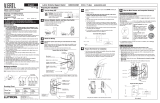
BMW i Wallbox
Installation Instructions
Freude am Fahren
BMW i

2

BMW i Wallbox
Installation Instructions
EN
3
Contents
INFORMATION 7
Safety information 7
Intended use 9
About this manual 9
Package 9
OVERVIEW 11
Displays and controls 11
SPECIFICATIONS 12
General criteria for selecting an installation site 12
Specifications for the electrical connection 13
Required space 14
Recommended installation positions 14
INSTALLATION 16
Installation requirements 16
Removing the housing cover 16
Removing the termination panel cover 17
Removing the terminal cover 18
Surface-mounted cable routing – cable inlet from above 18
Surface-mounted cable routing – cable inlet from below 19
Cable inlet from behind – cable in the wall 19
Cable openings 20
Installing the Wallbox 20
ELECTRICS 25
Connection diagram with open termination panel cover 25
Connecting the supply cable 26
Using the supply terminals (spring-type terminal) 26
SETTINGS 28
DIP switch settings 28
COMMISSIONING 30
General commissioning procedure 30

4
Commissioning mode / Self-test 30
Safety tests 31
Installing the terminal cover 31
Installing the termination panel cover 31
Installing the housing cover 33
MISCELLANEOUS 34
Dimensions 34
Technical data 35
MAINTENANCE 38
Replacing the fuse 38
DISPOSAL 39
SOFTWARE UPDATE 40
PRODUCT INFORMATION PAGE 41
INDEX 42

EN
5
Legal information
Bayerische Motorenwerke Aktiengesellschaft
Munich, Germany
www.bmw.com
Original installation instructions
Copyright ©2016 BMW AG Munich
This documentation contains information protected by copyright. All rights reserved, especially
the right of reproduction and distribution. No part of this documentation may be reproduced
(photocopying, scanning or any other procedures) or processed, copied or distributed in any form
using electronic systems without the written consent of Bayerische Motorenwerke Aktiengesellschaft.
Contraventions are liable to compensation.

6
About this manual
Read these instructions carefully and study the device to familiarise yourself with it before you
attempt to install, operate or service it. The following special information may be displayed in
this documentation or on the device to warn you of possible dangers or to draw your attention to
information which explains or simplifies a procedure.
Symbols used
You will find information and warnings about possible dangers at various points in the manual. The
symbols used in the manual mean the following:
WARNING
Means that death or serious physical injury may occur if the appropriate precautions are not
taken.
CAUTION
Means that property damage or minor physical injury may occur if the appropriate precautions
are not taken.
IMPORTANT
Means that property damage may occur if the appropriate precautions are not taken.
ESD
This warning points out the possible consequences of touching electrostatically sensitive
components.
Note
Indicates procedures which do not involve any danger of injury.
The installation instructions should be kept for future use. You can download the Wallbox operating
instructions here: http://www.bmwgroup.com/360electric/index.html.
Information on equipment and functions
This manual contains a list of all the systems and functions that are currently available. It therefore also
describes systems and functions which may not be available to you as a result of the device version
or the specific installation and configuration of your device. In rare instances this may also mean that
there are differences between the description and your device.
Note
Your BMW dealer will be delighted to help find a qualified installation contractor.

EN
7
INFORMATION
Safety information
WARNING
Electrical danger.
The Wallbox must be installed, commissioned and serviced by suitably trained, qualified
and authorised electricians
(1)
who bear full responsibility for compliance with current
standards and installation regulations.
Please note that an additional overvoltage protection may be required by vehicles or
national regulations.
Please refer to national connection and installation standards.
Only connect voltages and circuits in the right-hand connection zone (Ethernet, terminals
for control cables) which are safely isolated from dangerous voltages (for example adequate
insulation).
Before commissioning the device check that all screw and terminal connections are tight.
The termination panel cover must never be left opened without supervision. Fit the
termination panel cover when you leave the Wallbox.
Do not make any unauthorised changes or modifications to the Wallbox.
Repair work to the Wallbox is not permitted and may only be completed by the
manufacturer or a trained expert (Wallbox replacement).
Do not remove any identifiers such as safety symbols, warning instructions, rating plates,
labels or cable markings.
The Wallbox does not have its own mains switch. The residual-current-operated circuit
breaker and circuit breaker on the building insulation is used as a mains isolation device.
Only pull the charging cable out of the connector using the plug, not the cable.
Ensure that the charging cable is not mechanically damaged (kinked, jammed or run over)
and that the contact area does not come into contact with heat sources, dirt or water.
(1)
Persons who, as a result of their training, skills and experience and their knowledge of the relevant
standards, can assess the work assigned to them and identify possible dangers.
CAUTION
5 safety rules:
Switch off on all poles and from all sources.
Secure to prevent it being switched on again.
Verify isolation from the supply.
Earth and short-circuit.
Cover neighbouring live parts and cordon off danger areas.

8
IMPORTANT
Danger of damage.
Ensure that the Wallbox is not damaged by incorrect handling (housing cover, internal parts,
etc.).
On outdoor installations, do not open the termination panel cover when it is raining.
Danger of breaking the plastic housing.
- Do not use countersunk screws to secure the device.
- Do not tighten the securing screws with force.
- The installation the area must be completely flat (max. 1 mm difference between the
support and securing points). Do not bend the housing.
Information for trained personnel who may open the device:
Danger of damage. Electronic components may be destroyed if touched.
Before handling modules, perform an electrical discharge process by touching a metallic
earthed object.
A failure to follow the safety information may result in a danger of death, injury and damage to the
device. The device manufacturer cannot accept any liability for claims resulting from this.

EN
9
Intended use
The Wallbox is a charging station for indoor and outdoor use on which electric or
plug-in hybrid vehicles can be charged. No other devices, such as electric tools, may be connected to
it. The Wallbox is designed for installation on a wall or on a pedestal. Comply with the relevant national
regulations for installing and connecting the Wallbox.
The intended use of the device in every case includes compliance with the ambient conditions for
which this device was developed.
The Wallbox was developed, manufactured, tested and documented on the basis of the relevant safety
standards. If you comply with the instructions and safety information described for its intended use, the
product normally will not pose any danger in terms of property damage or to the health of people.
The instructions contained in this manual must be followed to the letter. Otherwise sources of danger
may be created or safety equipment may be rendered inoperable. In addition to the safety information
provided in this manual, the safety and accident prevention regulations relating to the specific device
must be followed.
Not all versions/options are available in all countries as a result of technical or statutory restrictions.
About this manual
This manual and the functions described in it are valid for devices of the following type:
BMW i Wallbox
This manual is designed exclusively for trained personnel. These are people who, as a result of their
training, skills and experience and their knowledge of the relevant standards, can assess the work
assigned to them and identify possible dangers.
The illustrations and explanations contained in this manual refer to a typical version of the device. Your
device version may differ from this.
Please refer to the operating manual for information and instructions for operating the device.
Package
Package BMW i Wallbox
Wallbox 1x
Installation manual 1x
Operating manual 1x

10
Package BMW i Wallbox
Drilling template 1x
Double membrane seal M32 or ¾'' NPT (clamping range 14-21 mm) 1x
Double membrane seal M16 (clamping range 7-12 mm) 2x
Fastening kit for wall mounting
Wall plugs for M8, Fischer UXR-10 4x
Wafer-head screw M8x100 4x

EN
11
OVERVIEW
Displays and controls
BMW i Wallbox
Functions:
Charging electric or plug-in hybrid vehicles
1 Status LED
2 Charging cable plug holder
3 Charging cable plug

12
SPECIFICATIONS
General criteria for selecting an installation site
The Wallbox has been designed for indoor and outdoor use. It is therefore necessary to ensure the
correct installation conditions and protection for the device at the installation site.
Take into account the local electrical installation regulations, fire prevention regulations and
accident prevention regulations as well as the rescue routes at the site.
Do not install the Wallbox at locations:
Which are used as escape and rescue routes.
Which are inside potentially explosive zones (EX environment).
At which the Wallbox is exposed to ammonia gases (for example in or near stables).
At which the Wallbox may be damaged by falling objects (for example suspended ladders or
car tyres).
At which the Wallbox is on a direct personnel route and people could stumble over the
connected charging cable.
At which the Wallbox may be struck by jets of water (for example due to neighbouring manual
car wash systems, pressure washers or garden hoses).
At which the installation surface does not have sufficient strength to withstand the mechanical
stresses.
If possible, install the Wallbox so that it is protected from direct rainfall so as to avoid the effects of
weather, icing, damage by hailstones or the like.
If possible install the Wallbox so that it is protected from direct sunlight to prevent the charging
current being reduced or the charging process being interrupted as a result of excessive
temperatures on components of the Wallbox.
Ensure that you comply with the permitted ambient conditions, see "Technical data", Page 35.
Ensure compliance with national and international installation standards and regulations, for
example IEC 60364-1 and IEC 60364-5-52.
Ensure compliance with national regulations (for example the charging column regulation
in Germany) for the implementation of the EU Directive (2014/94/EU) relating to the
binding technical minimum specifications for sockets and vehicle couplings for charging
electric or plug-in hybrid vehicles in areas accessible to the public. This regulation relates to
charging points on public land as well as department store or customer car parks, for example.
Charging points on private carports or private garage entrances are not generally publicly
accessible charging points in the sense of this regulation.
Note
If the device is installed in a location where it is not protected from the weather, for example on
an outdoor car park, the charging current will be reduced to 16 A if the temperature exceeds
the limit value. The charging process may subsequently also be shut down.

EN
13
Specifications for the electrical connection
When it is delivered, the Wallbox is set to 10 A.
Set the maximum current using the DIP switches to suit the installed circuit breaker, see "DIP switch
settings".
Selecting the residual-current-operated circuit breaker
The supply cable must be permanently wired into the existing building installation and comply with the
national statutory regulations.
Each Wallbox must be connected using a separate residual-current-operated circuit breaker. No
other circuits may be connected to this residual-current-operated circuit breaker.
Residual-current-operated circuit breaker of at least type A (30 mA trip current).
Additional measures must be taken in the device to protect it in the event the DC fault currents
(>6m A DC) occur. Compliance with the specifications of the vehicle manufacturer is also
mandatory.
The rated current I
N
must be selected to suit the circuit breaker and the back-up fuse.
Selecting the circuit breaker
When selecting the circuit breaker, also take the increased ambient temperatures in the control cabinet
into consideration. In certain circumstances this may require a reduction in the charging current to
increase the system availability.
Set the rated current to suit the model plate details in conjunction with the required charge rating (DIP
switch settings for the charging current) and the supply cable.
Selecting the supply cable
When selecting the supply cable, take into account the possible reduction factors and the increased
ambient temperatures in the internal connection area of the Wallbox, see the temperature rating of the
supply terminals. In certain circumstances this may require an increase in the cable cross-section and
an adjustment in the temperature resistance of the supply cable.
Mains isolation device
The Wallbox does not have its own mains switch. The residual-current-operated circuit breaker and/or
the circuit breaker in the supply cable are used as a mains isolation device.

14
Required space
The space shown in the diagram below (shaded area) will allow the Wallbox to be installed and
operated easily. If you wish to install several Wallboxes next to each other, maintain a distance of at least
200mm (8") between each of them.
Dimensions in millimetres (inches)
Recommended installation positions
When selecting the installation position, taken note of the position of the charge connector on your
vehicle and the direction in which you normally park it. Examples:

EN
15
BMW i3 BMW PHEV
1 Recommended installation position
2 Alternative installation position

16
INSTALLATION
Installation requirements
Comply with the installation regulations.
The electrical connection (supply cable) must be prepared.
Acclimatisation
If there is a temperature difference of more than 15°C between the means of transport and
installation site, the Wallbox must be allowed to acclimatise for at least two hours before it is
opened.
Opening the Wallbox immediately may cause condensation to form inside it and thus damage the
device when it is switched on. The device may also suffered damage in certain circumstances at a
later time after the installation.
Ideally the Wallbox should be stored for a few hours at the installation site before being installed.
If this is not possible, the Wallbox should not be stored outdoors or in a vehicle over night in low
temperatures (< 5°C).
List of tools
The following tools will be required for the installation work:
Slot head screwdriver for the supply terminals, blade width 5.5 mm
Cross head screwdriver PH2
Torx screwdriver T40
Removing the housing cover
Interlocks
1. Press the two interlocks 1 for the housing
cover on the underside of the Wallbox
upwards.
The housing cover should then jump out
slightly at the bottom.

EN
17
Removing the housing cover
2. Swing the housing cover forwards a little on
the underside 1.
3. Then release the housing cover by raising it 2.
Note
Keep the housing cover in the packaging to
prevent it being scratched or suffering other
damage.
Removing the termination panel cover
1. Undo the four screws used to secure the
termination panel cover 1.
ESD
Danger of damage. Electronic components may be destroyed if touched.
Before handling modules, perform an electrical discharge process by touching a metallic
earthed object.

18
2. Remove the termination panel cover. The
termination panel 2 is now accessible.
3. Remove the silica bag from the termination
panel and dispose of it properly.
Removing the terminal cover
WARNING
Electrical danger.
The terminal cover may only be opened by authorised electricians with the appropriate training
and qualifications.
1. Undo the to fastening screws on the terminal
cover 1.
2. Remove the terminal cover over the supply
terminals.
Surface-mounted cable routing – cable inlet from above
The connection cables may be inserted from
above through the opening in the housing in the
external frame.
1. Break off the marked point 1 on the internal
housing section for this purpose.

EN
19
2. Route the supply cable in a loop to the cable
gland 2.
Comply with the maximum bending radii of the
cable.
Surface-mounted cable routing – cable inlet from below
1. Route the supply cable in a loop to the cable
gland 2.
Comply with the maximum bending radii of the
cable.
Cable inlet from behind – cable in the wall
Note
The cable is inserted straight from the wall directly from behind into the device. Ensure that the
Wallbox is correctly positioned for this purpose so that the cable opening is directly above the
cable. Do not exceed the bending radii.

20
Cable openings
1 Bushing / Double membrane seal M32, supply
cable
Flush-mounted socket
A double flush-mounted socket with a separating
web may be used for safe separation.
A Supply cable
Cable openings
Break off cable openings
1. Place the housing on a stable surface.
2. Carefully remove the required cable openings
using a hammer and slot head screwdriver.
3. Then insert the appropriate bushings, cable
glands or double membrane seals.
4. Fit the Wallbox with the supplied cable glands
or blind glands if a cable opening is no longer
to be used
Installing the Wallbox
The supplied fastening material is suitable for concrete, brick and wood (without wall plugs). A suitable
fastening method must be selected for other surfaces.
/