Page is loading ...

GRUNDFOS
PRODUCT GUIDE
MS
Submersible Motors
60 Hz
MS.book Page 1 Wednesday, January 26, 2005 3:25 PM

Contents
2
Contents
Mission
Product data
Introduction 4
Grundfos MS Motors Introduction 4
MS Motor Selection 4
Product Range 5
Model Designation 6
Nameplate 6
Features
MS 402 7
MS 4000 8
Special Construction Features 8
MS 6000 9
Special Construction Features 9
Operating Conditions
Operating Conditions 10
MS 402 11
MS 4000 12
MS 6000 13
Construction
Material specification for MS 402 14
Material specification for MS 4000 15
Material specification for MS 6000 16
Selection
Motor Operation 17
Motor Loading, Failure and Lifetime 17
Motor Efficiency 18
Application and Selection Issues 19
Mechanical Installation
Submersible Motor Cooling 20
Required Cooling Flow and Velocity 20
Water Temperature and Motor Derating 20
Shroud/Flow Inducer Sleeve/Cooling Sleeve 21
Special (Non Water Well) Applications 22
Electrical Installation
Submersible Power Cable 24
Cable Selection 25
Technical Data
Outline Drawing MS 402 26
Dimensions and Weights MS 402 26
Outline Drawing MS 4000 27
Dimensions and Weights MS 4000 27
Outline Drawing MS 6000 28
Dimensions and Weights MS 6000 28
Electrical Data
Grundfos Motors Specifications 29
Transformer Capacity 31
Engine-Driven Generators 32
Motor Protection Chart 33
Motor Cable Selection Chart
(Motor Service to Entrance) 35
Single Phase, 60 Hz 35
Three Phase, 60 Hz 35
Accessories
CU 3 37
Benefits of CU 3/R100 38
Control functions 39
Features and benefits 40
Motor protection via CU 3 41
Control unit CU 3 with R100
remote control and printer 41
R100 Menus 42
Menu Structure of the R100 Remote Control 43
Complete Borehole Monitoring
System with CU 3 and SM 100 44
Further product documentation
Sources of product documentation 45
WinCAPS® 45
WebCAPS® 46
MS.book Page 2 Wednesday, January 26, 2005 3:25 PM

3
Mission
GBJ - Bjerringbro, Denmark
GMU - Fresno, California GPU - Olathe, Kansas
GMX - Monterrey, Mexico GPA - Allentown, Pennsylvania GCA - Oakville, Ontario
- to successfully develop, produce, and sell high quality
motors and pumping systems worldwide, contributing to a
better quality of life and healthier environment
• One of the 3 largest pump companies in the world
• The second largest manufacturer of submersible motors in the world
• World headquarters in Denmark
• North American headquarters in Kansas City - Manufacturing in Fresno, California
• 60 companies in 40 countries
• More than 10 million motors and pumps produced annually worldwide
• North American companies operating in USA, Canada and Mexico
• Continuous reinvestment in growth and development enables the company to
BE responsible, THINK ahead, and INNOVATE
MS.book Page 3 Wednesday, January 26, 2005 3:25 PM

4
MS Motors
Product data
Introduction
Grundfos MS Motors Introduction
Grundfos Submersible motors are designed specifically
for operation in and under water.
The motor and power cable are designed and sealed to
prevent water from contacting any part of the electrical
circuit.
The motors are equipped with a high-capacity thrust
bearing to support the total thrust of the pumping unit.
The Grundfos submersible motor depends on
surrounding water to carry away heat; most require a
specified flow of water for adequate cooling.
MS Motor Selection
Selecting the best submersible motor for a particular
pump application requires careful consideration of
several factors. The motor must match the pump in
mounting dimensions, and must also have adequate Hp
load rating and thrust rating to support the pump over
its entire operating range. Grundfos 4” and 6” submers-
ible motors are built to NEMA standards, which define
their physical dimensions, electrical ratings, and thrust
ratings. The motor must be capable of operation at the
water temperature and velocity presented by the instal-
lation.
Grundfos literature specifies the maximum water
temperature and minimum required velocity past the
motor. Motor operation in water that exceeds the rated
temperature may be allowable at reduced loading,
depending on the particular motor.
If the installation does not assure the specified velocity
past the motor- because of well diameter, well inflow
above the pump or other reasons - a sleeve over the
motor should be used to induce the required velocity.
MS.book Page 4 Wednesday, January 26, 2005 3:25 PM

5
Product data
MS Motors
Product Range
Motor size
MS 402 MS 4000 (R) MS 6000 (R)
4" 4" 6"
Hp Kw Hp Kw Hp Kw
Power range, direct-on-line
- 1 x 115 V .50 .37 - - - -
- 1 x 230 V .33 - 1.50 .25 - 1.1 2.0 - 5.0 1.5 - 4.0 - -
- 3 x 230 V .50 - 2.0 .37 - 1.50 3.0 - 7.5 2.2 - 5.5 7.5 - 30.0 5.5 - 22.0
- 3 x 460 V .50 - 2.0 .37 - 1.50 3.0 - 10.0 2.2 - 7.5 7.5 - 40.0 5.5 - 30.0
- 3 x 575 V .50 - 2.0 .37 - 1.50 3.0 - 10.0 2.2 - 7.5 7.5 - 40.0 5.5 - 30.0
Allowed installation
- Vertical .33 - 2.0 .25 - 1.5 2.0 - 10.0 1.5 - 7.5 7.5 - 40.0 5.5 - 30.0
- Horizontal .33 - 2.0 .25 - 1.5 2.0 - 10.0 1.5 - 7.5 7.5 - 40.0 5.5 - 30.0
MS.book Page 5 Wednesday, January 26, 2005 3:25 PM

6
Model Designation
MS 402
MS 4000
MS 6000
Nameplate
Example MS 4 02
Motor Submersible
Min. borehole
diameter in inches
Generation
- = Stainless Steel AISI 304
Example MS 4 000 R
Motor Submersible
Min. borehole
diameter in inches
Generation
- = Stainless Steel AISI 304
R = Stainless Steel AISI 904L
I = Stainless Steel AISI 304 + De-rated
RE = Stainless Steel AISI 904 L + FKM
EI = Stainless Steel AISI 304 + De-rated + FKM
Example MS 6 000 R
Motor Submersible
Min. borehole
diameter in inches
Generation
- = Stainless Steel AISI 304
R = Stainless Steel AISI 904L
I = Stainless Steel AISI 304 + De-rated
RE = Stainless Steel AISI 904 L + FKM
EI = Stainless Steel AISI 304 + De-rated + FKM
TM03 0542 0502TM03 0543 0502TM03 0544 0502
THERMALLY PROTECTED
X
XX
XX.X
P1
+
SF
CODE
HP
X.XX
XXXX
XXXXXXXX
CONTROLBOX
DUTY
XX.X
XXX
WEIGHT
RPM
COSMAX.AMPS
XXXX
CONT.
MADE IN DENMARK
PH1 Hz60 XX.X
X.XX
YYWW
XXXXXXXX
PROD.NO.
PC.
MS402
VAC
0.5
ft/s INS.CL.
X
XXX
Lb
F
XXXF
3w
XXX
XX.X
+
SF
CODE
HP
X.XX
XXXX
XXXXXXXXCONTROLBOX
DUTY
XX.X
XXX
WEIGHT
RPM
COSMAX.AMPS
XXXX
CONT.
MADE IN DENMARK
PH1 Hz60 XX.X
X.XX
XXXXXXXXPROD.NO.
PC.
MS4000
VAC
0.5
ft/s INS.CL.
X
XXX
Lb
F
XXX
F
THERMALLY PROTECTED
P1 YYWW
MS6000
X.XXXX.X60
Hz
3
MADE IN DENMARK
CONT.DUTY
VAC
MAX.SF.AMPS
COS
RPM
WEIGHT
XXX
XXX
XX.X
X.XX
XXXX
XXX 0.5
XXX
Lb
INS.CL.
X
XX.X
X.XX
XXXX
HP
-
-
-
-
SF CODEX
ft/s
X
F
XXXXXXXXPROD.NO.
PC.
P1 YYWW
Product data
MS Motors
MS.book Page 6 Wednesday, January 26, 2005 3:25 PM

7
MS Motors
Features
MS 402
• Complete Range of Motors from 1/3 - 2 Hp 1 ph,
2-wire; 3-wire and 3 Ph.
• Designed for 4" and Larger Wells
• Corrosion Resistance All Stainless Steel Exterior
Construction
• Cast Stainless Steel Machined Top
• Stainless Steel Splined Shaft
• Stator Windings Hermetically Encapsulated in Stain-
less Steel
• Polyurethane Self Healing Resin
• 900 lb. Thrust Rating
• Water Lubricated
• Internal Water Circulation System Enhances Motor
Cooling
• No Cooling Sleeve Needed up to 85°F
• Rated up to 104°F with 1/2 ft./sec. flow Past
the Motor
• Filter Check Valve
• Michell Type Carbon/Ceramic Thrust Bearing
• Pressure Equalization Diaphragm
• Sand Slinger
• Bellows Type Shaft-Seal
• Epoxy Coated Bearing Support
• Built-In Surge Protection
• Replaceable Motor Lead
• NEMA Mounting Dimensions
• UL Recognized
• CSA Certified
2-wire motors are only available up to 1.5 Hp
65495 0205
MS.book Page 7 Wednesday, January 26, 2005 3:25 PM

8
Features
MS Motors
MS 4000
• Complete Range of Motors from 3 - 10 Hp 1 ph,
3-wire and 3 Ph.
• Designed for 4" and Larger Wells
• Corrosion Resistance All Stainless Steel Exterior
Construction
• Stainless Steel Splined Shaft
• Stator Windings Hermetically Encapsulated in Stain-
less Steel
• Water Lubricated
• Internal Water Circulation System Enhances Motor
Cooling
• No Cooling Sleeve Needed up to 85°F
• Rated up to 104°F with 1/2 ft./sec. flow Past
the Motor
• Filter Check Valve
• Michell Type Carbon/Ceramic Thrust Bearing
• 1500 lb. Thrust Rating
• Pressure Equalization Diaphragm
• Sand Slinger
• Tungsten Carbide/Ceramic Shaft-Seal, for Long Life
in Sandy Applications
• Steel Bearing Support
• 7 1/2 and 10 Hp Equipped with Tempcon
Temperature Sensor
• 3 Ph Motors Work with MTP 75 and CU 3 Motor Pro-
tection System
• Replaceable Motor Lead
• NEMA Mounting Dimensions
• CSA Certified
Special Construction Features
• Available in a 904L Grade of Stainless Steel and/or
FKM, for aggressive Applications
• Available In an Industrial Version for
Industrial Applications
• Designed for Long Life and Lower operating Costs.
Tempcon optional on 3 and 5 HP
65492 0205
MS.book Page 8 Wednesday, January 26, 2005 3:25 PM

9
MS 6000
• Complete Range of Motors from 7 1/2 - 40 Hp 3 Ph
• Designed for 6" and Larger Wells
• Corrosion Resistance All Stainless Steel Exterior
Construction
• Stainless Steel Splined Shaft
• Stator Windings Hermetically Encapsulated in Stain-
less Steel
• Water Lubricated
• Internal Water Circulation System Enhances Motor
Cooling
• No Cooling Sleeve Needed up to 85°F
• Rated up to 104°F with 1/2 ft./sec. flow Past
the Motor
• Filtered Check Valve
• Michell Type Carbon/Ceramic Thrust Bearing
• 6000 lb. Thrust Rating
• Pressure Equalization Diaphragm
• Sand Slinger
• Tungsten Carbide/Ceramic Shaft-Seal, standard
• Optional Silicon/Carbide Shaft-Seal, for Long Life in
Sandy Applications
• Steel Bearing Support
• Equipped With Tempcon Temperature Sensor as
Standard
• Work with MTP 75 and CU 3 Motor Protection
System
• Replaceable Motor Lead
• NEMA Mounting Dimensions
• CSA Certified
Special Construction Features
• Available in a 904L Grade of Stainless Steel and/or
FKM, for aggressive Applications
• Available In an Industrial Version for
Industrial Applications
• Designed for Long Life and Lower operating Costs.
GR7291
Features
MS Motors
MS.book Page 9 Wednesday, January 26, 2005 3:25 PM

10
MS Motors
Operating Conditions
Operating Conditions
Cooling
The cooling of the motor depends on the temperature
and the flow velocity of the pumped liquid past the
motor.
To ensure sufficient cooling, the values for maximum
temperature of the pumped liquid and its flow velocity
must be kept.
It is reccomended always to ensure a minimum cooling
flow of 0.50 f/s.
Free Convection
Free convection is achieved when the diameter of the
borehole is at least 2" (~ 50 mm) bigger than the outer
diameter of the motor.
The motor should always be installed above the bore-
hole screen. If a flow sleeve is used, the motor can be
placed in the screen.
Calculation of the flow velocity:
Required data:
Q
min
: Flow in gpm
D
i
: Borehole diameter in inches
d
A
: Motor diameter in inches
Fig. 1 Drawing for cooling flow
TM02 2269 4001
v
Q
min
2826 D
i
2
d
A
2
–
⎝⎠
⎛⎞
×
------------------------------------------------- -
f/s=
N
D
motor
D
borehole
MS.book Page 10 Wednesday, January 26, 2005 3:25 PM

11
Operating Conditions
MS Motors
MS 402
Pumped Liquids
MS 402 is generally recommended for operation in
water without any appreciable amount of chloride at
common groundwater temperatures.
• MS402 is made of 304 stainless steel AISI
Sand Content
Max. sand content in pumped liquid: 50 ppm.
Ambient Pressure
Max. 20 bar ~ 290 psi.
It is generally not recommended to install the motor for
operation in a vacuum.
Cooling
Cooling of the motor depends on temperature and
velocity of flow of the pumped liquid past the motor. In
order to ensure sufficient cooling, the values for max.
temperature of the pumped liquid and its velocity of flow
past the motor stated in the table to the right must be
kept.
Note: The temperature limits are based on the condi-
tion that the other operating conditions are as specified
in this Product Guide.
In case the actual temperature of the pumped liquid is
higher than the one stated in the table, or if the oper-
ating conditions are especially unfavourable, please
contact Grundfos.
Free Convection
Free convection is achieved when the diameter of the
borehole is at least 2" (~ 50 mm) bigger than the outer
diameter of the motor, or if the motor is installed in the
borehole screen.
Fig. 2 Free Convection
Fig. 3 Flow of Pumped Liquid past the Motor
Velocity of Flow Past
the Motor
Max. Temperature of Pumped Liquid
Vertical
Installation
Horizontal
Installation
0.0 f/s
(Free Convection)
30°C
(86°F)
Flow sleeve
recommended
Min. 0.25 f/s
40°C
(104°F)
40°C
(105°F)
TM00 5122 5094TM00 5123 5094
ø95
ø145
MS.book Page 11 Wednesday, January 26, 2005 3:25 PM

12
MS 4000
Pumped Liquids
The MS 4000 motors are available in several versions
to enable use in various liquids.
• MS 4000 is generally recommended for use in water
without chloride.
MS 4000 is made of 304 stainless steel AISI
• MS 4000 R is recommended for use in aggressive
liquids.
MS 4000 R is made of 904L stainless steel AISI
• MS 4000 RE is recommended for use in aggressive
and slightly contaminated liquids.
MS 4000 RE is made of 904L stainless steel AISI,
and the original rubber parts have been
replaced with FKM.
In cases of doubt, please make an analysis of the liquid
and contact Grundfos.
Sand Content
Max. sand content in pumped liquid: 50 ppm.
Ambient Pressure
Max. 60 bar ~ 870 psi.
It is generally not recommended to install the motor for
operation in a vacuum.
Cooling
Cooling of the motor depends on temperature and
velocity of flow of the pumped liquid past the motor. In
order to ensure sufficient cooling, the values for max.
temperature of the pumped liquid and its velocity of flow
past the motor stated in the table to the right must be
kept.
It is recommended to always install the motor in the
borehole screen.
Note: The temperature limits are based on the condi-
tion that the other operating conditions are as specified
in this Product Guide.
In case the actual temperature of the pumped liquid is
higher than the one stated in the table, or if the oper-
ating conditions are especially unfavourable, please
contact Grundfos.
Free Convection
Free convection is achieved when the diameter of the
borehole is at least 2" (~ 50 mm) bigger than the outer
diameter of the motor, or if the motor is installed in the
borehole screen.
Fig. 4 Free Convection
Velocity of Flow Past
the Motor
Max. Temperature of Pumped Liquid
Vertical
Installation
Horizontal
Installation
0.0 f/s
(Free Convection)
30°C
(86°F)
Flow sleeve
recommended
Min. 0.25 f/s
40°C
(104°F)
40°C
(105°F)
TM00 5688 1395
D
D
motor
borehole
Operating Conditions
MS Motors
MS.book Page 12 Wednesday, January 26, 2005 3:25 PM

13
Operating Conditions
MS Motors
MS 6000
Pumped Liquids
The MS 6000 motors are available in several versions
to enable use in various liquids.
• MS 6000 is generally recommended for use in
common groundwater.
MS 6000 is made of 304 stainless steel AISI.
• MS 6000 R is recommended for use in aggressive
liquids.
MS 6000 R is made of 904L stainless steel AISI.
• MS 6000 RE is recommended for use in aggressive
and slightly contaminated liquids.
MS 4000 RE is made of 904 stainless steel AISI,
and the rubber parts are made of FKM.
In cases of doubt, please make an analysis of the liquid
and contact Grundfos.
Sand Content
Max. sand content in pumped liquid: 50 ppm.
Ambient Pressure
Max. 60 bar ~ 870 psi.
It is generally not recommendable to install the motor
for operation in a vacuum.
If this cannot be avoided, please contact Grundfos for
guidance.
Cooling
Cooling of the motor depends on temperature and
velocity of flow of the pumped liquid past the motor. In
order to ensure sufficient cooling, the values for max.
temperature of the pumped liquid and its velocity of flow
past the motor stated in the table to the right must be
kept.
Free Convection
Free convection is achieved when the diameter of the
borehole is at least 2" (~ 50 mm) bigger than the outer
diameter of the motor.
Fig. 5 Free Convection
Velocity of Flow Past
the Motor
Max. Temperature of Pumped Liquid
Vertical
Installation
Horizontal
Installation
0.0 f/s
(Free Convection)
30°C
(86°F)
Flow sleeve
recommended
Min. 0.25 f/s
40°C
(104°F)
40°C
(105°F)
TM00 5688 1395
D
D
motor
borehole
MS.book Page 13 Wednesday, January 26, 2005 3:25 PM

14
MS Motors
Construction
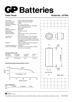
Material specification for MS 402
Standard Version
Example: MS 402
Pos. Component Material AISI
1a Plug Plastics, PELD
2 Shaft Stainless steel 431
2a Stop ring (upthrust) Polyethylene, PP
5c Housing for radial bearing Silumin
5b
Radial bearing,
stationary
Ceramic
6 Bearing journal Tungsten carbide
7 Filling compound Polyurethane
8 Stator sleeve Plastics, PET
9 Stator winding Copper wire
10 Stator housing Stainless steel 403
11
Radial bearing,
stationary
Ceramic
12 Bearing journal Tungsten carbide
13 Intermediate ring Sintered steel
14
Thrust bearing ring,
rotating
Ceramic
15
Thrust bearing shoes.
stationary
Carbon
16 Rotor lamination Magnetic sheet steel
17 Stator lamination Magnetic sheet steel
21 Nut Stainless steel 304
22 Staybolt Stainless steel 304
25 Cover plate Stainless steel 304
25a Screw Stainless steel 304
27 Sand shield NBR rubber
32 Bellows seal NBR rubber
32a Lock ring Composite PPS
50,
74
Screw Stainless steel 304
Rotor rods
Cast aluminium or cop-
per
Motor liquid SML-2
TM00 4736 4094
••••••••••••
••••••••••••
••••••••••••
••••••••••••
••••••••••••
••••••••••••
••••••••••••
•••••••••••••••
••••••••••••••
•••••••••••••••
••••••••••••••
•••••••••••••••
••••••••••••••
•••••••••••••••
••••••••••••••
•••••••••••••••
••••••••••••••
•••••••••••••••
••••••••••••••
•••••••••••••••
••••••••••••••
•••••••••••••••
••••••••••••••
•••••••••••••••
••••••••••••••
•••••••••••••••
••
•
•
••
•
••
•
••
•
•
•
•
•
•
•
•
•
•
•
•
•
•
•
•
•
•
•
•
•
•
•
•
•
•
•
•
•
•
•
•
•
•
•
•
•
•
•
•
•
•
•
•
•
•
•
•
•
•
•
•
•
•
•
•
•
•
•
•
•
•
•
•
•
•
•
•
•
•
•
•
•
•
•
•
•
•
•
•
•
•
•
•
•
•
•
•
•
•
•
•
•
•
•
•••••
••••••
•••••
••••••
•••••
••••••
•••••
••••••
•••••
••••••
•••••
••••••
•••••
••••••
•••••
••••••
•••••
••••••
•••••
••••••
•••••
••••••
•••••
••••••
•••••
••••••
•••
•
•••••••
•••••••
••••••••
••••••••
••••••••
••••••••
•••••••••
••••••••
•••••••••
••••••••
••••••••
•••••••
•••••••
••••••
•••••
••••
•••
•
•
•
•
•••
••••
•••••
••••••
•••••••
•••••••
••••••••
••••••••
••••••••
••••••••
•••••••••
••••••••
••••••••
••••••••
••••••••
•••••••
•••••••
••
•
••
•
••
•
••
•
••
•
••
•
••
•
••
•
••
•
••
•
••
•
••
•
••
•
••
•
••
•
••
•
••
•
••
•
••
•
••
•
••
•
••
•
••
•
••
•
••
•
••
•
••
•
•
•
•
•
•
•
•
•
•
•
•
•
•
•
•
•
•
•
•
•
•
•
•
•
•
•
•
••
•
••
•
••
•
••
•
••
••
•••••
•
••
•••••
••••••••••••••••••
•••••••••••••••••
••••••••••••••••••
•••••••••••••••••
••••••••••••••••••
•••••••••••••••••
••••••••••••••••••
••••••••••••••••••••••••••
••••••••••••••••••••••••••
••••••••••••••••••••••••••
••••••••••••••••••••••••••
••••••••••••••••••••••••••
••••••••••••••••••••••••••
••••••••••••••••••••••••••
••••••••••••••••••••••••••
••••••••••••••••••••••••••
••••••••••••••••••••••••••
••••••••••••••••••••••••••
••••••••••••••••••••••••••
•••••••••••••••••••••••
•••••••••••••••••••••••
•••••••••••••••••••••••
•••••••••••••••••••••••
•••••••••••••••••••••••
•••••••••••••••••••••••
•••••••••••••••••••••••
•
•
•
•
•
•
•
•
•
•
•
•
•
•
•
•
•
•
•
•
•
•
•
•
•
•
•
•
•
•
•
•
•
•
•
•
•
•
•
•
•
•
•
•
•
•
•
••
•••
••••
•••••••••••••••••••••••••••
••••••••••••••••••••••••••
•••••••••••••••••••••••••••
••••••••••••••••••••••••••
•••••••••••••••••••••••••••
••••••••••••••••••••••••••
•••••••••••••••••••••••••••
••••••••••••••••••••••••••
•••••••••••••••••••••••••••
••••••••••••••••••••••••••
•••••••••••••••••••••••••••
••••••••••••••••••••••••••
•••••••••••••••••••••••••••
••••••••••••••••••••••••••
•••••••••••••••••••••••••••
••••••••••••••••••••••••••
•••••••••••••••••••••••••••
••••••••••••••••••••••••••
•••••••••••••••••••••••••••
••••••••••••••••••••••••
••••••••••••••••••••••••••
••••••••••••••••••••••••
••••••••••••••••••••••••••
••••••••••••••••••••••••
••••••••••••••••••••••••••
••••••••••••••••••••••••
••••
••
••••
••
••••
••
••••
••
••••
••
••••
••
••••
••
••••
••
••••
••
••••
••
••••
••
••••
••
••••
••
••••
••
••••
••
••••
••
••••
••
••••
••
••••
••
••••
••
••••
••
••••
••
••••
••
••••
•
••
••••
•••••
••••••
•••••••
••••••••
••••••••
••••••••
••••••••
••••••••
••••••••
••••••••
••••••••
••••••••
••••••••
••••••••
••••••••
••••••••
••••••••
••••••••
••••••••
••••••••
••••••••
••••••••
••••••••
••••••••
••••••••
••••••••
••••••••
•••••••
••••••
•••••
••••
••
•
••
•••
•••
•••
•••
•••
•••
••••
•••
••••
•••
••••
••••
••••
••••
•••••
•••
•••
•••
••
•
••
•
••
•
••
•
••
•
••
•
••
•
••
•
••
•
••
•
••
•
••
•
••
•
••
•
••
•
••
•
••
•
••
•
••
•
••
•
••
•
••
•
••
•
••
•
••
•
••
•
••
•
••
•
••
•
••
••
••
••
••
••
•••
••
•••
•••
•••
•••
••
•
••
•••
••
•
•
•
2b
22
25
25a
5b
6
8
10
16
17
8
14
9
15
7
13
50
11
12
74
5a
32
32a
1a
21
27
2a
MS.book Page 14 Wednesday, January 26, 2005 3:25 PM

15
Construction
MS Motors
Material specification for MS 4000
Standard Version
R-Version
RE-Version
Example: MS 4000
Pos. Component Material AISI
1 Stator Stainless steel 304
2 Rotor Stainless steel 431
3 Thrust bearing, (stationary) Carbon
4 Radial bearing, complete Ceramic
5 Bearing pipe, complete Cast iron GG20
6 Thrust bearing, (rotating) Ceramic
7 Clamping ring
10 Bearing retainer
11 Adjusting screw
12 Diaphragm NBR rubber
13 Motor end shield Stainless steel 304
15 Nut (special)
16 Lock washer
18/
21
Nut Stainless steel 316
20 Motor cable
22 Staybolt Stainless steel 316
22a Staybolt complete Stainless steel 316
24 O-ring
25 Shaft seal housing Stainless steel 304
27 Spline protector NBR rubber
28 Supporting ring for 27
29 Sand shield NBR rubber
30 Spring
31 Supporting ring
32 Seal ring, upper (stationary)
NBR rubber
Tungsten carbide
33 O-ring
34 Seal ring, lower (rotating) Tungsten carbide
70 Motor liquid SML-2
Pos. Component Material AISI
1 Stator Stainless steel 904L
13 Motor end shield Stainless steel 904L
18/
21
Nut Stainless steel 904L
22 Staybolt Stainless steel 904L
22a Staybolt complete Stainless steel
904L
316
25 Shaft seal housing Stainless steel 904L
Pos. Component Material AISI
12 Diaphragm FKM
27 Spline protector FKM
29 Sand shield FKM
32 Seal ring upper, (stationary) FKM ceramic
34 Seal ring lower, (rotating)
FKM
ceramic
TM00 5068 4994
18
16
13
12
15
7
10
11
3
6
4
1
2
5
24
21
22
22a
MS.book Page 15 Wednesday, January 26, 2005 3:25 PM

16
Material specification for MS 6000
Standard Version
R-Version
RE-Version
Example: MS 6000
Pos. Component Material AISI
1 Stator Stainless steel 304
2 Rotor
2a Stop ring PTFE
3 Thrust bearing, (stationary) Carbon
4 Radial bearing, lower
Ceramic/tungsten
carbide
5 Radial bearing, upper
Ceramic/tungsten
carbide
6 Thrust bearing (rotating)
7 Clamping flange Steel
10 Thrust cover Steel
11 Adjusting screw Steel
12 Diaphragm NBR rubber
13 Motor end shield Stainless steel 304
22 Bolt Stainless steel 904L
22a Priming screw Stainless steel 316
27 Sand shield NBR rubber
28 Retaining bolts Stainless steel
29 Shaft seal housing Stainless steel 304
30 Spring Stainless steel
32
Seal ring complete
(stationary)
NBR
Ceramic
33 O-ring
34
Seal ring complete
(rotating)
Tungsten carbide
42 Stop for bearing Steel
46 Hex socket screw Stainless steel 304
46a Washer Nyltite
47 Screw Steel
49 Retaining spring Steel
50 Screw for motor cable Stainless steel 304
70 Motor liquid SML-2
Pos. Component Material AISI
1 Stator Stainless steel 904L
13 Motor end shield Stainless steel 904L
22 Bolt Stainless steel 904L
22a Priming screw Stainless steel 904L
46 Hex socket screw Stainless steel 904L
50 Screw for motor cable Stainless steel 904L
Pos. Component Material AISI
12 Diaphargm FKM
27 Sand shield FKM
32
Seal ring complete
(stationary)
FKM
Ceramic
TM03 0536 0205
30
27
32
34
50
33
5
2a
2
1
42
11
10
7
12
22
29
22a
28
4
6
3
49
46a
46
47
13
Construction
MS Motors
MS.book Page 16 Wednesday, January 26, 2005 3:25 PM

17
MS Motors
Selection
Motor Operation
Most deep well submersible type pumps are powered
by electric motors. The optimum power unit used is
dependent on several physical and environmental
factors, which include the horsepower required for
pumping, the annual hours of operation and the avail-
ability and cost of energy.
How does a motor "know" what horsepower to deliver?
Electric motors draw power in proportion to the applied
load. Although a motor is rated for a certain output
power (this is the number stamped on the nameplate),
that motor can deliver a wide range of power depending
on the voltage and frequency provided and the torque
demanded by the shaft load.
Power is the rate of energy use. Input power to a elec-
trical motor is measured in kW, the motor converts that
electric power into mechanical power.
Output power is the product of speed (rpm) and torque
(ft.-lb.). For a given voltage and frequency combination,
the motor will always operate at a point on a specific
torque vs. speed curve.
The units of both output power and torque are generally
specified as a percentage of the motors full load rated
value on the manufactures performance curve.
A small change in speed produce large changes in
available torque near the normal (close to rated) oper-
ating speed.
Thus as load torque increases, the rotational speed will
drop slightly (increased slip) as the motor load
increases.
As soon as voltage is supplied to the motor, the motor
“knows” the power to deliver by speeding up until it puts
out exactly the same torque as the load requires at that
speed.
At start-up, the motor produces torque higher than the
torque required by the driven load, accelerating the
pump shaft to full load speed.
A submersible pump is a centrifugal device which
exhibits variable torque load characteristics, it takes
very little torque to accelerate the load at low speed.
A centrifugal pump requires torque approximately
proportional to the square of its speed. The maximum
speed of a induction motor is a function of the number
of poles and line frequency.
Typical speeds associated with submersible motors,
based on the number of poles and a line frequency of
60 Hz are; 2p - 3600 rpm (sync.)/ 3450 rpm (@ full load)
and 4p - 1800 rpm (sync.)/ 1760 (@ full load).
The synchronous speed on any motor can be calcu-
lated when the number of poles and operating
frequency is known, using the formula below:
N = f x 120/P where; N = sync. speed (rpm), P = poles, f = frequency (Hz)
Note: Actual induction motor speed at full load will be
2-5% less than the synchronous speed calculated using
the formula above.
A pump driven by two different motors of the same
nominal speed (rpm), but different Hp ratings, will draw
approximately the same power.
Under steady-state conditions the speed of operation
does not change significantly, unless the motor is too
small and stalls.
Motor Loading, Failure
and Lifetime
Motor load is commonly expressed as the percentage
of output power to rated output. Because output power
(load) is difficult to measure in the field, motor load is
usually estimated by measuring input power (kWI) and
assuming an efficiency.
It can also be estimated by measuring kVA and
assuming both power factor and efficiency. Failure of a
motor occurs when insulation breaks down from heat
and mechanical stresses.
The temperature of the windings are primarily depen-
dent on the current (amps) draw through them and the
ability of motor to dissipate the heat generated to the
ambient environment. The higher the temperature, the
shorter the life. A 10°C(50F) rise can halve motor life.
Motor current draw increases with load; as a result,
motors that operate outside established load and
temperature ratings, will operate fewer hours before
failure.
The voltage supplied to the motor terminals have a
significant impact on motor life.
Motors are designed to operate at a utilization voltage
level or range, which is generally lower than the elec-
trical system distribution voltage provided to the utility
meter. Motors can operate within a range of voltages;
but above a certain voltage, destructive arcing and
insulation deterioration can occur.
Conversely, as voltage drops, more current is needed
to maintain torque and power; so the motor runs hotter
and its life is shortened.
In addition to the overall voltage provided to the motor,
voltage unbalance must be considered. If the voltages
on the three phases to the motor are not well balanced,
one winding will carry more current and may over heat
and fail.
MS.book Page 17 Wednesday, January 26, 2005 3:25 PM

18
Selection
MS Motors
Most electrical utilities guarantees voltages to a +/-5
percent standard; for "480" service voltage will be
between 456 V and 504 V at the meter; for "240"
service, the voltages must be between 228 V and
252 V.
If a motor is damaged as a result of over or under
voltage outside the service limits, the utility may be
liable for damages.
Because motors will operate cooler with higher volt-
ages, reasonable over voltage levels rarely causes
problems. There are only small variations in power
factor and efficiency near rated conditions, volt- amps
for a particular load can be assumed constant over the
range of voltage guarantee by the utility.
The maximum continuous load sustained by a motor is
indicated by the service factor. A motor with a service
factor of 1.15 can maintain a 115% overload; provided
voltages are at the rated level and well balanced and
the insulation system can be maintained at or below
rated temperature. The actual motor load percentage
can be calculated using the formula listed below:
where; Em = motor efficiency
IHp = Input Horsepower
Motor design and economic criteria have forced motor
manufactures to build less service factor (SF) into
motors.
The SF allows the motor to provide power under
optimal conditions at the nameplate rated power times
the SF. At rated conditions, (ie. 100 Hp motor with a SF
of 1.15 is designed to provide 115 HP under continuos
load).
A 1982 survey of motor manufacturers showed six of
seven respondents recommending loading at 100
percent of rated power or less while only one still
suggests loading up to SF rating.
For this reason, it is recommended that motor loading
not exceed 100% of the nameplate horsepower rating.
It is best to consider the SF as a contingency against
over loading as a result of low voltage, current imbal-
ance and/or adverse ambient conditions.
Motor Efficiency
An electric motor operates at a relatively constant effi-
ciency and speed over a wide range of loadings.
Efficiency does not change significantly with age of the
motor or the load applied to it.
Motor efficiency is practically constant at motor loads
between 50 and 100%.
Reducing motor size for the sake of energy conserva-
tion, as a result of efficiency increases associated with
loading the motor closer to full magnetic saturation
(100% load) is not recommended.
As a general rule, a bigger motor that is underloaded
(down to 50 percent) is more efficient than a fully
loaded smaller motor driving the same load. Submers-
ible pump motors will have slightly lower efficiencies
than surface motor as a result of the compact design
requirements and the need for internal cooling/lubri-
cating fluid.
Most submersible motors have an efficiency stamped
on the nameplate. The average or nominal efficiency
values associated with "canned/ hermetically sealed"
type submersible motors are listed in the Electrical Data
Section.
% Motor Load
EM IHp×
Rated HP
------------------------- -
100× =
MS.book Page 18 Wednesday, January 26, 2005 3:25 PM

19
Application and Selection Issues
The term application not only refers to the end use of
the product but also the parameters which affect the
selection of the correct submersible motor and pump
products. The primary considerations involved with the
selection of submersible motors are discussed as
follows:
• The Insulation System. The insulation system is
the key to long motor life. The life of the insulation
system is affected by three major factors: Load,
Duty Cycle, and Temperature Rise. The load of a
motor is described in horsepower or kilowatts and is
defined as the work required to perform a function.
The load created by pumps is a result of the rotation
of impeller(s) to create a pressure forcing fluid
through a system. The duty cycle is the time period,
which the motor is operating. It is continuous or in-
termittent. Temperature rise is the difference be-
tween the operating temperature of the windings
and the temperature of the medium to cool the mo-
tor. The rise of the motor is directly affected by the
load and duty cycle. Extra load in the form of a ser-
vice factor increases the temperature rise of the
winding.
The total temperature must never exceed the maximum
capacity of the insulation system. Submersible motors
used for water well service normally employ class “F”
insulation (150°F rise), but are designed for a class A
temperature rise (60°F).
• Cooling. Submersible motors are no different than
conventional motors, in that the heat generated
within the motor must be dissipated. The tempera-
ture rise within the motor is limited to a value which
when added to the temperature of the external cool-
ing medium does not exceed the maximum temper-
ature capacity of the insulation system. The ability
to dissipate the heat depends on two factors: (1)
The temperature of the cooling medium (ambient)
and (2) the rate of cooling medium flow past the mo-
tor external surfaces. Excess ambient temperature
and reduced flow rate both require derating of the
load capability of the unit. The derating of the load
reduces the temperature rise of the winding within
the limits set by the heat dissipation capacity of the
cooling medium.
• Materials of Construction. Submersible pumps
and motors are also selected based on the chemical
and physical make-up of the water in which they will
be submerged. Sea water applications require spe-
cialized construction due to the corrosive water en-
countered. A standard motor will not survive highly
corrosive water submergence, while a specially de-
signed motor will.
• Design Factors. Other factors, which affect sub-
mersible motor selection, are voltage, depth of in-
stallation, thrust and controls. It is necessary that
the voltage and frequency variations be within the
limits set in NEMA MGI-18 (submersible motors for
deep well pumps). The maximum recommended
depth for most submersible motors relates to 290
psi on the unit (approx. 2000 feet). The thrust deliv-
ered by the pump must be less than the capacity of
the thrust bearing of the submersible motor. Con-
trols must be quick trip, ambient compensated type
to quickly pull an improperly applied or defective
motor off the line so that no damage occurs.
Submersible construction and design for 4"and 6" sizes
are covered by NEMA standards.
Selection
MS Motors
MS.book Page 19 Wednesday, January 26, 2005 3:25 PM

20
MS Motors
Mechanical Installation
Submersible Motor Cooling
The key to long submersible motor life is good cooling.
Most submersible pumps rely on moving heat away
from the motor by forced convection. The ambient/
produced fluid is typically drawn by the motor in the
course of pumping to accomplish this task. Grundfos
Submersible Motors are designed to operate at full load
in water up to 30°C (86°F) free convection, and 40C
(104F) provided the flow velocity can be maintained at
a minimum of 0.25 feet per second (fps).
Required Cooling Flow
and Velocity
AWWA specifications state the maximum motor diam-
eter and the minimum inside diameter of the well shall
be in such relationship that under any operating condi-
tion the water velocity past the motor shall not exceed
12 fps (3.7 m/s) nor be less than 0.5 fps (0.15 m/s). The
AWWA specifications are principally applicable to
motors 6-inch and larger, as most 4-inch motor designs
are based on a minimum cooling flow velocity of 0.25
fps (0.08 m/s) at rated ambient temperature. Table 1
relates flow, casing and motor size requirements to
accomplish minimum cooling velocity.
(Table 1) Minimum Submersible Cooling Flow
Requirements
Grundfos Submersible Motors require no cooling fluid
flow past the motor, when the produced fluid tempera-
ture is 30°C (86°F) or less. Cooling by free convection
in such cases, is contingent on no adverse operating
conditions present such as; poor power, high stop/start
frequency, presence of incrustating deposits on the
motor surface, etc. Detramental operating conditions
are difficult to identify or predict, and for this reason, the
minimum cooling flow should be provided whenever
possible - regardless of the ambient fluid temperature.
Water Temperature and Motor
Derating
As previously stated, the full motor capacity is a func-
tion of ambient fluid temperature and flow past the
motor.
When the ambient temperature exceeds the tempera-
ture at which the motor performance is based, the
motor must be derated and/or cooling velocity
increased. Table 2 provides typical derating criteria for
hermetically sealed/canned type submersible motors.
Such motors should not be used in applications which
exceed 60°C (140°F) regardless of any special provi-
sions incorporated into the system. AWWA specifica-
tions state that the motor temperature shall not exceed
the allowable operating temperature of the motor thrust
and radial bearings, and in no case shall it exceed the
temperature rating of the motor insulation system.
When the service duty exceeds 40°C (104°F) pumps
and motors fitted with NBR rubber components are
subject to reduced life if not replaced on a regular basis.
A minimum replacement interval of three years is
recommended.
FKM elastomers (rubber compounds) are recom-
mended any time the normal ambient fluid temperature
exceeds 104°F. Allowable % Max. Namplate Amps
Derated for Ambient Water Temp. @ .5 fps
(Table 2) Allowable % Max Nameplate Amps
Derated. for Ambient Water Temp at .50fps.
Casing/Sleeve
I.D. (inches)
4" Motor
(0.25 fps)
6" Motor
(0.5 fps)
41.2-
57.0-
6139
72025
83045
10 50 90
12 80 140
14 110 200
16 150 280
18 - 380
Note: At the velocity specified in the table the temperature differential
between the motor surface and ambient water will range from 5° - 15°C
(10-30°F).
Water Temp. 0 - 3 Hp 5 - 15 Hp 20 - 40 Hp
30°C (86°F) 100% 100% 100%
35°C (95°F) 100% 100% 90%
40°C (104°F) 100% 90% 80%
45°C (113°F) 90% 80% 70%
50°C (122°F) 80% 70% 60%
55°C (130°F) 70% 60% 45%
60°C (140°F) 50% - -
Note: Derating % is based on an ambient fluid temperature of 30°C
(86°F) @ 0.5 fps, consult motor manufacture for specific maximum full-
load cooling water temperature without derating. Typical base abient fluid
temperature rating for various manufactures of submersible motors used
in the water supply industry range from 25°C to 40°C, with 30°C being
the most prominent.
MS.book Page 20 Wednesday, January 26, 2005 3:25 PM
/