
GRUNDFOS INSTRUCTIONS
CRE, CRIE, CRNE, SPKE, CRKE,
MTRE, CME
Grundfos E-pumps with MLE frequency-controlled, asynchronous
motors
Installation and operating instructions

English (US)
2
English (US) Installation and operating instructions
Original installation and operating instructions.
CONTENTS
Page
1. Limited warranty
Products manufactured by GRUNDFOS PUMPS CORPORATION
(Grundfos) are warranted to the original user only to be free of
defects in material and workmanship for a period of 24 months
from date of installation, but not more than 30 months from date
of manufacture. Grundfos' liability under this warranty shall be
limited to repairing or replacing at Grundfos' option, without
charge, F.O.B. Grundfos' factory or authorized service station,
any product of Grundfos' manufacture. Grundfos will not be liable
for any costs of removal, installation, transportation, or any other
charges which may arise in connection with a warranty claim.
Products which are sold but not manufactured by Grundfos are
subject to the warranty provided by the manufacturer of said
products and not by Grundfos' warranty. Grundfos will not be
liable for damage or wear to products caused by abnormal
operating conditions, accident, abuse, misuse, unauthorized
alteration or repair, or if the product was not installed in
accordance with Grundfos' printed installation and operating
instructions.
To obtain service under this warranty, the defective product must
be returned to the distributor or dealer of Grundfos' products from
which it was purchased together with proof of purchase and
installation date, failure date, and supporting installation data.
Unless otherwise provided, the distributor or dealer will contact
Grundfos or an authorized service station for instructions. Any
defective product to be returned to Grundfos or a service station
must be sent freight prepaid; documentation supporting the
warranty claim and/or a Return Material Authorization must be
included if so instructed.
GRUNDFOS WILL NOT BE LIABLE FOR ANY INCIDENTAL OR
CONSEQUENTIAL DAMAGES, LOSSES, OR EXPENSES
ARISING FROM INSTALLATION, USE, OR ANY OTHER
CAUSES. THERE ARE NO EXPRESS OR IMPLIED
WARRANTIES, INCLUDING MERCHANTABILITY OR FITNESS
FOR A PARTICULAR PURPOSE, WHICH EXTEND BEYOND
THOSE WARRANTIES DESCRIBED OR REFERRED TO
ABOVE.
Some jurisdictions do not allow the exclusion or limitation of
incidental or consequential damages and some jurisdictions do
not allow limit actions on how long implied warranties may last.
Therefore, the above limitations or exclusions may not apply to
you. This warranty gives you specific legal rights and you may
also have other rights which vary from jurisdiction to jurisdiction.
1. Limited warranty
2
2. Symbols used in this document
3
3. General information
3
4. General description
3
4.1 Pumps without factory-fitted sensor
3
4.2 Pumps with pressure sensor
3
4.3 Settings
3
5. Mechanical installation
3
5.1 Motor cooling
3
5.2 Outdoor installation
3
6. Electrical connection
4
6.1 Single-phase pumps
4
6.2 Three-phase pumps, 1.5 - 10 hp
4
6.3 Three-phase pumps, 15-30 hp
6
6.4 Signal cables
9
6.5 E-pump electrical connections
9
6.6 Bus connection cable
10
7. Modes
10
7.1 Overview of modes
10
7.2 Operating mode
10
7.3 Control mode
10
8. Setting up the pump
11
8.1 Factory setting
11
9. Setting by means of control panel
11
9.1 Setting of operating mode
12
9.2 Setpoint setting
12
10. Setting by means of R100
12
10.1 Menu OPERATION
14
10.2 Menu STATUS
15
10.3 Menu INSTALLATION
16
10.4 Typical display settings for constant-pressure E-pumps
23
10.5 Typical display settings for analog-input E-pumps
24
10.6 Grundfos GO Remote
25
11. Setting by means of PC Tool E-products
26
12. Priority of settings
26
13. External forced-control signals
26
13.1 Start/stop input
26
13.2 Digital input
27
14. External setpoint signal
27
15. Bus signal
28
16. Other bus standards
28
17. Indicator lights and signal relay
28
18. Emergency operation (only 15-30 hp)
30
19. Insulation resistance
31
20. Maintenance and service
31
20.1 Cleaning of the motor
31
20.2 Relubrication of motor bearings
31
20.3 Replacement of motor bearings
31
20.4 Replacement of varistor (only 15-30 hp)
31
20.5 Service parts and service kits
31
21. Technical data - three-phase pumps, 1.5 - 10 hp
31
21.1 Supply voltage
31
21.2 Overload protection
31
21.3 Leakage current
31
21.4 Inputs/output
31
22. Technical data - three-phase pumps, 15-30 hp
32
22.1 Supply voltage
32
22.2 Overload protection
32
22.3 Leakage current
32
22.4 Inputs/output
32
22.5 Other technical data
33
23. Disposal
33
Warning
Prior to installation, read these installation and
operating instructions. Installation and operation
must comply with local regulations and accepted
codes of good practice.

3
English (US)
2. Symbols used in this document
3. General information
These installation and operating instructions are a supplement to
installation and operating instructions for the corresponding
standard pumps CR, CRI, CRN, CRK, SPK, MTR, CHI and CM.
For instructions not mentioned specifically here, please see
installation and operating instructions for the standard pump.
4. General description
Grundfos E-pumps have standard motors with integrated
frequency converter. The pumps are for single-phase or three-
phase power supply connection.
4.1 Pumps without factory-fitted sensor
The pumps have a built-in PI controller and can be set up for an
external sensor enabling control of the following parameters:
• pressure
• differential pressure
• temperature
• differential temperature
•flow rate
• liquid level in a tank.
From factory, the pumps have been set to control mode
uncontrolled. The PI controller can be activated by means of
R100.
4.2 Pumps with pressure sensor
The pumps have a built-in PI controller and are set up with a
pressure sensor enabling control of the pump discharge
pressure.
The pumps are set to control mode controlled. The pumps are
typically used to hold a constant pressure in variable-demand
systems.
4.3 Settings
The description of settings apply both to pumps without factory-
fitted sensor and to pumps with a factory-fitted pressure sensor.
Setpoint
The desired setpoint can be set in three different ways:
• directly on the pump control panel
• via an input for external setpoint signal
• by means of Grundfos wireless remote control R100.
Other settings
All other settings can only be made by means of the R100.
Important parameters such as actual value of control parameter,
power consumption, etc. can be read via the R100.
If special or customized settings are required, use Grundfos PC
Tool E-products. Contact your local Grundfos company for more
information.
5. Mechanical installation
The pump must be secured to a solid foundation by means of
bolts through the holes in the flange or baseplate.
5.1 Motor cooling
To ensure sufficient cooling of motor and electronics, observe the
following requirements:
• Make sure that sufficient cooling air is available.
• Keep the temperature of the cooling air below 104 °F (40 °C).
• Keep cooling fins and fan blades clean.
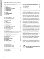
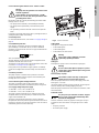
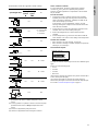
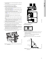
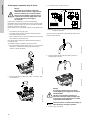
5.2 Outdoor installation
When installed outdoors, the pump must be provided with a
suitable cover to avoid condensation on the electronic
components. See fig. 1.
Fig. 1 Examples of covers
Remove the drain plug pointing downwards in order to avoid
moisture and water build-up inside the motor.
Vertically mounted pumps are IP55 after removal of the drain
plug. Horizontally mounted pumps change enclosure class to
IP54.
Warning
If these safety instructions are not observed, it
may result in personal injury!
Warning
The surface of the product may be so hot that
it may cause burns or personal injury.
Caution
If these safety instructions are not observed,
it may result in malfunction or damage to the
equipment.
Note
Note
Notes or instructions that make the job easier
and ensure safe operation.
Note
Note
In order to retain the UL/cUL approval, follow the
additional installation procedures on page 35.
TM00 8622 0101 - TM02 8514 0304

English (US)
4
6. Electrical connection
For description of how to connect E-pumps electrically, see the
following pages:
6.1 Single-phase pumps, page 4
6.2 Three-phase pumps, 1.5 - 10 hp, page 4
6.3 Three-phase pumps, 15-30 hp, page 6.
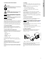
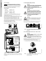
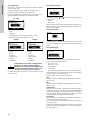
6.1 Single-phase pumps
6.1.1 Preparation
Before connecting the E-pump to the power supply, take the
issues illustrated in the figure below into consideration.
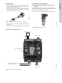
Fig. 2 Power supply-connected pump with power switch,
backup fuse, additional protection and protective
grounding
6.1.2 Protection against electric shock - indirect contact
Protective ground leads must always have a yellow/green (PE) or
yellow/green/blue (PEN) color marking.
6.1.3 Backup fuses
For recommended fuse sizes, see section 22.1 Supply voltage on
page 32.
6.1.4 Additional protection
If the pump is connected to an electric installation where an
ground leakage circuit breaker (ELCB) is used as additional
protection, the circuit breaker must be of a type marked with the
following symbol:
The total leakage current of all the electrical equipment in the
installation must be taken into account.
The leakage current of the motor in normal operation can be seen
in section 22.3 Leakage current on page 32.
During start and at asymmetrical supply systems, the leakage
current can be higher than normal and may cause the ELCB to
trip.
6.1.5 Motor protection
The pump requires no external motor protection. The motor
incorporates thermal protection against slow overloading and
blocking (IEC 34-11, TP 211).
6.1.6 Protection against voltage transients
The pump is protected against voltage transients by built-in
varistors between phase-neutral and phase-ground.
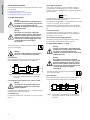
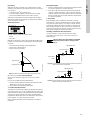
6.2 Three-phase pumps, 1.5 - 10 hp
6.2.1 Preparation
Before connecting the E-pump to the power supply, take the
issues illustrated in the figure below into consideration.
Fig. 3 Power supply-connected pump with power switch,
backup fuses, additional protection and protective
grounding
Warning
The user or the installer is responsible for the
installation of correct grounding and protection
according to current national and local
standards. All operations must be carried out by
qualified personnel.
Warning
Never make any connections in the pump
terminal box unless all electric supply circuits
have been switched off for at least 5 minutes.
Note for instance that the signal relay may be
connected to an external supply which is still
connected when the power supply is
disconnected.
The above warning is indicated on the motor terminal
box by this yellow label:
Warning
The surface of the terminal box may be above
158 °F (70 °C) when the pump is operating.
TM02 0792 0101
Warning
The pump must be grounded and protected
against indirect contact in accordance with
national regulations.
N
PE
L
N
L
PE
ELCB
Warning
The user or the installer is responsible for the
installation of correct grounding and protection
according to current national and local
standards. All operations must be carried out by
qualified personnel.
Warning
Never make any connections in the pump
terminal box unless all electric supply circuits
have been switched off for at least 5 minutes.
Note for instance that the signal relay may be
connected to an external supply which is still
connected when the power supply is
disconnected.
The above warning is indicated on the motor terminal
box by this yellow label:
TM00 9270 4696
ELCB
L1
L2
L3
L2
L1
L3
PE
ELCB

5
English (US)
6.2.2 Protection against electric shock - indirect contact
EN 50178 and BS 7671 specify the following precautions when
leakage current > 3.5 mA:
• The pump must be stationary and installed permanently.
• The pump must be permanently connected to the power
supply.
• The grounding connection must be carried out as duplicate
leads.
Protective ground leads must always have a yellow/green (PE) or
yellow/green/blue (PEN) color marking.
6.2.3 Backup fuses
For recommended fuse sizes, see section 21.1 Supply voltage on
page 32.
6.2.4 Additional protection
If the pump is connected to an electric installation where an
ground leakage circuit breaker (ELCB) is used as additional
protection, the circuit breaker must be of a type marked with the
following symbols:
This circuit breaker is type B.
The total leakage current of all the electrical equipment in the
installation must be taken into account.
The leakage current of the motor in normal operation can be seen
in section 21.3 Leakage current on page 31.
During start and at asymmetrical supply systems, the leakage
current can be higher than normal and may cause the ELCB to
trip.
6.2.5 Motor protection
The pump requires no external motor protection. The motor
incorporates thermal protection against slow overloading and
blocking (IEC 34-11, TP 211).
6.2.6 Protection against voltage transients
The pump is protected against voltage transients by built-in
varistors between the phases and between phases and ground.
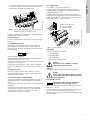
6.2.7 Supply voltage and power supply
3 x 460-480 V - 10 %/+ 10 %, 50/60 Hz, PE.
3 x 208-230 V - 10 %/+ 10 %, 50/60 Hz, PE.
The supply voltage and frequency are marked on the pump
nameplate. Make sure that the pump is suitable for the power
supply of the installation site.
The wires in the terminal box must be as short as possible.
Excepted from this is the protective ground lead which must be so
long that it is the last one to be disconnected in case the cable is
inadvertently pulled out of the cable entry.
Fig. 4 Power connection
Cable glands
Cable glands comply with EN 50626.
• 2 x M16 cable gland
• 1 x M20 cable gland
• 2 x M16 knock-out cable entries.
Grid types
Three-phase E-pumps can be connected to all grid types.
6.2.8 Start/stop of pump
When the pump is switched on via the power supply, it will start
after approx. 5 seconds.
If a higher number of starts and stops is desired, use the input for
external start/stop when starting/stopping the pump.
When the pump is switched on via an external on/off switch, it will
start immediately.
Automatic restart
However, automatic restart only applies to fault types set up to
automatic restart. These faults could typically be one of these
faults:
• temporary overload
• fault in the power supply.
Warning
The pump must be grounded in accordance with
national regulations.
As the leakage current of 5-10 hp (4 - 7.5 kW)
motors is > 3.5 mA, take extra precautions when
grounding these motors.
ELCB
TM03 8600 2007
Warning
If the supply cable is damaged, it must be
replaced by qualified personnel.
Warning
Do not connect three-phase E-pumps to a power
supply with a voltage between phase and ground
of more than 440 V.
Caution
The number of starts and stops via the power
supply must not exceed 4 times per hour.
Note
Note
If a pump set up for automatic restart is stopped
due to a fault, it will restart automatically when
the fault has disappeared.
L1
L2
L3
L1
L2
L3

English (US)
6
6.2.9 Connections
As a precaution, the wires to be connected to the following
connection groups must be separated from each other by
reinforced insulation in their entire lengths:
Group 1: Inputs
• start/stop terminals 2 and 3
• digital input terminals 1 and 9
• setpoint input terminals 4, 5 and 6
• sensor input terminals 7 and 8
• GENIbus terminals B, Y and A
All inputs (group 1) are internally separated from the power-
conducting parts by reinforced insulation and galvanically
separated from other circuits.
All control terminals are supplied with protective extra-low voltage
(PELV), thus ensuring protection against electric shock.
Group 2: Output (relay signal, terminals NC, C, NO)
The output (group 2) is galvanically separated from other circuits.
Therefore, the supply voltage or protective extra-low voltage can
be connected to the output as desired.
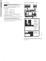
6.2.10 Three-phase pumps, 1.5 - 10 hp
Group 3: Power supply (terminals L1, L2, L3)
Fig. 5 Connection terminals
A galvanic separation must fulfill the requirements for reinforced
insulation including creepage distances and clearances specified
in EN 60335.
6.3 Three-phase pumps, 15-30 hp
6.3.1 Preparation
Before connecting the E-pump to the power supply, take the
issues illustrated in the figure below into consideration.
Fig. 6 Power supply-connected pump with power switch,
backup fuses, additional protection and protective
grounding
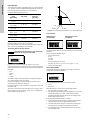
6.3.2 Protection against electric shock - indirect contact
EN 61800-5-1 specifies that the pump must be stationary and
installed permanently when the leakage current is > 10 mA.
One of the following requirements must be fulfilled:
• A single protective ground lead (7 AWG minimum copper)
Fig. 7 Connection of a single protective ground lead using
one of the leads of a 4-core power cable
(7 AWG minimum)
Note
Note
If no external on/off switch is connected,
connect terminals 2 and 3 using a short wire.
TM05 2985 0812
6: GND (frame)
5: +10 V
4: Setpoint input
3: GND (frame)
2: Start/stop
Group 1
Group 2
Group 3
13: GND (frame)
12: Analog output
11: Digital input 4
10: Digital input 3
1: Digital input 2
9: GND (frame)
8: +24 V
7: Sensor input
B: RS-485B
Y: Screen
A: RS-485A
Warning
The user or the installer is responsible for the
installation of correct grounding and protection
according to current national and local
standards. All operations must be carried out by
qualified personnel.
Warning
Never make any connections in the pump
terminal box unless all electric supply circuits
have been switched off for at least 5 minutes.
Note for instance that the signal relay may be
connected to an external supply which is still
connected when the power supply is
disconnected.
Warning
The surface of the terminal box may be above
158 °F (70 °C) when the pump is operating.
TM00 9270 4696
Warning
The pump must be grounded in accordance with
national regulations.
As the leakage current of 15-30 hp motors is
> 10 mA, take extra precautions when grounding
these motors.
TM04 3021 3508
L1
L2
L3
L2
L1
L3
PE
ELCB

7
English (US)
• Two protective ground leads of the same cross-sectional area
as the power supply leads, with one lead connected to an
additional ground terminal in the terminal box.
Fig. 8 Connection of two protective ground leads using two of
the leads of a 5-core power supply cable
Protective ground leads must always have a yellow/green (PE) or
yellow/green/blue (PEN) color marking.
6.3.3 Backup fuses
For recommended fuse sizes, see section 22.1 Supply voltage on
page 32.
6.3.4 Additional protection
If the pump is connected to an electric installation where an
ground leakage circuit breaker (ELCB) is used as additional
protection, the circuit breaker must be of a type marked with the
following symbols:
This circuit breaker is type B.
The total leakage current of all the electrical equipment in the
installation must be taken into account.
The leakage current of the motor in normal operation can be seen
in section 22.3 Leakage current.
During start and at asymmetrical supply systems, the leakage
current can be higher than normal and may cause the ELCB to
trip.
6.3.5 Motor protection
The pump requires no external motor protection. The motor
incorporates thermal protection against slow overloading and
blocking (IEC 34-11, TP 211).
6.3.6 Protection against voltage transients
The pump is protected against voltage transients in accordance
with EN 61800-3 and is capable of withstanding a VDE 0160
pulse.
The pump has a replaceable varistor which is part of the transient
protection.
Over time this varistor will be worn and need to be replaced.
When the time for replacement has come, R100 and PC Tool
E-products will indicate this as a warning. See section
20. Maintenance and service on page 31.
6.3.7 Supply voltage
3 x 460-480 V - 10 %/+ 10 %, 50/60 Hz, PE.
The supply voltage and frequency are marked on the pump
nameplate. Make sure that the motor is suitable for the power
supply of the installation site.
The wires in the terminal box must be as short as possible.
Excepted from this is the protective ground lead which must be so
long that it is the last one to be disconnected in case the cable is
inadvertently pulled out of the cable entry.
Fig. 9 Power connection
Cable glands
Cable glands comply with EN 50626.
• 1 x M40 cable gland
• 1 x M20 cable gland
• 2 x M16 cable gland
• 2 x M16 knock-out cable entries.
Grid types
Three-phase E-pumps can be connected to all grid types.
6.3.8 Start/stop of pump
When the pump is switched on via the power supply, it will start
after approx. 5 seconds.
If a higher number of starts and stops is desired, use the input for
external start/stop when starting/stopping the pump.
When the pump is switched on via an external on/off switch, it will
start immediately.
TM03 8606 2007
ELCB
TM03 8605 2007 - TM04 3048 3508
Warning
If the supply cable is damaged, it must be
replaced by qualified personnel.
Warning
Do not connect three-phase E-pumps to a power
supply with a voltage between phase and ground
of more than 440 V.
Caution
The number of starts and stops via the power
supply must not exceed 4 times per hour.
Torques, terminals L1-L3:
Min. torque: 1.6 ft-lbs
Max. torque: 1.8 ft-lbs

English (US)
8
6.3.9 Connections
As a precaution, the wires to be connected to the following
connection groups must be separated from each other by
reinforced insulation in their entire lengths:
Group 1: Inputs
• start/stop terminals 2 and 3
• digital input terminals 1 and 9
• setpoint input terminals 4, 5 and 6
• sensor input terminals 7 and 8
• GENIbus terminals B, Y and A
All inputs (group 1) are internally separated from the power-
conducting parts by reinforced insulation and galvanically
separated from other circuits.
All control terminals are supplied with protective extra-low voltage
(PELV), thus ensuring protection against electric shock.
Group 2: Output (relay signal, terminals NC, C, NO)
The output (group 2) is galvanically separated from other circuits.
Therefore, the supply voltage or protective extra-low voltage can
be connected to the output as desired.
Group 3: Power supply (terminals L1, L2, L3)
Fig. 10 Connection terminals
A galvanic separation must fulfill the requirements for reinforced
insulation including creepage distances and clearances specified
in EN 61800-5-1.
Note
Note
If no external on/off switch is connected, connect
terminals 2 and 3 using a short wire.
TM05 2986 0812
6: GND (frame)
5: +10 V
4: Setpoint input
3: GND (frame)
2: Start/stop
Group 2
Group 3
20: PT 100 B
19: PT 100 B
18: PT 100 A
17: PT 100 A
16: GND (frame)
15: +24 V
14: Sensor input 2
13: GND
12: Analog output
11: Digital input 4
10: Digital input 3
1: Digital input 2
9: GND (frame)
8: +24 V
7: Sensor input
B: RS-485B
Y: Screen
A: RS-485A
Group 1

9
English (US)
6.4 Signal cables
• Use screened cables with a conductor cross-section of min.
28 AWG and max. 16 AWG for external on/off switch, digital
input, setpoint and sensor signals.
• Connect the screens of the cables to frame at both ends with
good frame connection. The screens must be as close as
possible to the terminals. See fig. 11.
Fig. 11 Stripped cable with screen and wire connection
• Always tighten screws for frame connections whether a cable
is fitted or not.
• Make the wires in the pump terminal box as short as possible.
6.5 E-pump electrical connections
6.5.1 Connection of E-pump to Danfoss pressure sensor
MBS3000
The blue wire of the pressure sensor is connected to the #7
terminal of the E-pump. The brown wire of the pressure sensor is
connected to the #8 terminal of the E-pump.
See section 6.4 Signal cables on page 9 for additional details.
Fig. 12 Danfoss pressure sensor
6.5.2 Connection of E-pump to LiqTec®
Fig. 13 Connection of E-pump to LiqTec
TM02 1325 0901
TM05 1533 2911
TM03 0437 5104
Dry-running sensor
Set to automatic resetting
Connection terminals on E-pump:
2 (Start/Stop) and 3 (GND)
3
2
1 x 200-240 VAC
or
1 X 80-130 VAC
Brown
Black
Blue
White
Jumper cable

English (US)
10
6.6 Bus connection cable
6.6.1 New installations
For the bus connection, use a screened 3-core cable with a
conductor cross-section of 28-16 AWG.
• If the pump is connected to a unit with a cable clamp which is
identical to the one on the pump, connect the screen to this
cable clamp.
• If the unit has no cable clamp as shown in fig. 14, leave the
screen unconnected at this end.
Fig. 14 Connection with screened 3-core cable
6.6.2 Replacing an existing pump
• If a screened 2-core cable is used in the existing installation,
connect it as shown in fig. 15.
Fig. 15 Connection with screened 2-core cable
• If a screened 3-core cable is used in the existing installation,
follow the instructions in section 6.6.1 New installations on
page 10.
7. Modes
Grundfos E-pumps are set and controlled according to operating
and control modes.
7.1 Overview of modes
1) For this control mode the pump is equipped with a pressure
sensor. The pump may also be equipped with a temperature
sensor in which case the description would be constant
temperature in control mode controlled.
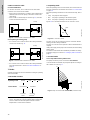
7.2 Operating mode
When the operating mode is set to Normal, the control mode can
be set to controlled or uncontrolled. See section 7.3 Control mode
on page 10.
The other operating modes that can be selected are Stop, Min. or
Max.
• Stop: the pump has been stopped
• Min.: the pump is operating at its minimum speed
• Max.: the pump is operating at its maximum speed.
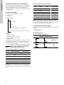
Figure 16 is a schematic illustration of min. and max. curves.
Fig. 16 Min. and max. curves
The max. curve can for instance be used in connection with the
venting procedure during installation.
The min. curve can be used in periods in which a minimum flow is
required.
If the power supply to the pump is disconnected, the mode setting
will be stored.
The remote control R100 offers additional possibilities of setting
and status displays. See section 10. Setting by means of R100 on
page 12.
7.3 Control mode
7.3.1 Pumps without factory-fitted sensor
The pumps are factory-set to control mode uncontrolled.
In control mode uncontrolled, the pump will operate according to
the constant curve set, fig. 17.
Fig. 17 Pump in control mode uncontrolled (constant curve)
TM02 8841 0904TM02 8842 0904
Operating modes Normal Stop Min. Max.
Control modes Uncontrolled Controlled
Constant
curve
Constant
pressure
1)
A
Y
B
A
Y
B
1
2
3
1
2
3
Pump
A
Y
B
A
Y
B
1
2
1
2
Pump
TM00 5547 0995TM00 7746 1304
Q
H
Max.
Min.
H
Q

11
English (US)
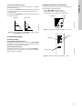
7.3.2 Pumps with pressure sensor
The pump can be set to one of two control modes, i.e. controlled
and uncontrolled, fig. 18.
In control mode controlled, the pump will adjust its performance,
i.e. pump discharge pressure, to the desired setpoint for the
control parameter.
In control mode uncontrolled, the pump will operate according to
the constant curve set.
Fig. 18 Pump in control mode controlled (constant pressure)
or uncontrolled (constant curve)
8. Setting up the pump
8.1 Factory setting
Pumps without factory-fitted sensor
The pumps have been factory-set to control mode uncontrolled.
The setpoint value corresponds to 100 % of the maximum pump
performance (see data sheet for the pump).
Pumps with pressure sensor
The pumps have been factory-set to control mode controlled.
The setpoint value corresponds to 50 % of the sensor measuring
range (see sensor nameplate).
9. Setting by means of control panel
The pump control panel, see fig. 19 or 20, incorporates the
following buttons and indicator lights:
• Buttons, and , for setpoint setting.
• Light fields, yellow, for indication of setpoint.
• Indicator lights, green (operation) and red (fault).
Fig. 19 Control panel, single-phase pumps, 0.5 - 1.5 hp
Fig. 20 Control panel, three-phase pumps, 1-30 hp
TM00 7668 0404
Q
H
set
H
Q
H
UncontrolledControlled
TM00 7600 0304TM02 8513 0304
Light fields Buttons
Indicator lights
Buttons
Indicator lights
Light fields

English (US)
12
9.1 Setting of operating mode
Settings available:
•Normal
•Stop
•Min.
•Max.
Start/stop of pump
Start the pump by continuously pressing until the desired
setpoint is indicated. This is operating mode Normal.
Stop the pump by continuously pressing until none of the light
fields are activated and the green indicator light flashes.
Setting to Min.
Press
continuously to change to the min. curve of the pump
(bottom light field flashes). When the bottom light field is on,
press for 3 seconds until the light field starts flashing.
To return to uncontrolled or controlled operation, press
continuously until the desired setpoint is indicated.
Fig. 21 Min. curve duty
Setting to Max.
Press continuously to change to the max. curve of the pump
(top light field flashes). When the top light field is on, press for
3 seconds until the light field starts flashing.
To return to uncontrolled or controlled operation, press
continuously until the desired setpoint is indicated.
Fig. 22 Max. curve duty
9.2 Setpoint setting
Set the desired setpoint by pressing the button or .
The light fields on the control panel will indicate the setpoint set.
See examples in sections 9.2.1 on page 12 and 9.2.2 on page 12.
9.2.1 Pump in control mode controlled (pressure control)
Example
Figure 23 shows that the light fields 5 and 6 are activated,
indicating a desired setpoint of 3 bar. The setting range is equal
to the sensor measuring range (see sensor nameplate).
Fig. 23 Setpoint set to 3 bar, pressure control
9.2.2 Pump in control mode uncontrolled
Example
In control mode uncontrolled, the pump performance is set within
the range from min. to max. curve. See fig. 24.
Fig. 24 Pump performance setting, control mode uncontrolled
10. Setting by means of R100
The pump is designed for wireless communication with
Grundfos remote control R100.
Fig. 25 R100 communicating with the pump via infra-red light
During communication, the R100 must be pointed at the control
panel. When the R100 communicates with the pump, the red
indicator light will flash rapidly. Keep pointing the R100 at the
control panel until the red LED diode stops flashing.
The R100 offers setting and status displays for the pump.
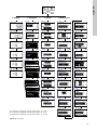
The displays are divided into four parallel menus (see fig. 34):
0. GENERAL (see operating instructions for the R100)
1. OPERATION
2. STATUS
3. INSTALLATION
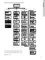
The figure above each individual display in fig. 34 refers to the
section in which the display is described.
TM00 7346 1304TM00 7345 1304
H
Q
H
Q
TM00 7743 0904TM00 7746 1304TM02 0936 0501
0
6
3
[bar]
H
Q

13
English (US)
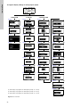
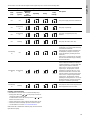
Fig. 26 Menu overview
0. GENERAL 1. OPERATION 2. STATUS 3. INSTALLATION
10.1.1 10.2.1 10.3.1 10.3.7
10.1.2 10.2.2 10.3.2 10.3.7
10.1.3 10.2.3 10.3.3 10.3.8
10.1.3 (1) 10.2.4 10.3.4 (3) 10.3.9 (1)
10.1.4 10.2.5 10.3.4 - 1 (2) 10.3.10
10.2.6 10.3.4 - 2 (2) 10.3.11 (1)
10.1.4 (1) 10.2.7 (2) 10.3.5 10.3.12
10.2.8 (2) 10.3.6 10.3.13 (1)
10.2.9 (1) 10.3.7 10.3.14 (1)
10.3.7 10.3.15 (1)
(1) This display only appears for three-phase pumps, 1.5 - 30 hp.
(2) This display only appears for three-phase pumps, 15 - 30 hp.
(3) This display only appears for three-phase pumps, 1.5 - 10 hp.

English (US)
14
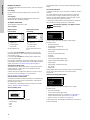
Displays in general
In the following explanation of the functions, one or two displays
are shown.
One display
Pumps without or with factory-fitted sensor have the same
function.
Two displays
Pumps without or with factory-fitted pressure sensor have
different functions and factory settings.
10.1 Menu OPERATION
The first display in this menu is this:
10.1.1 Setpoint
In control mode uncontrolled, the setpoint is set in % of the
maximum performance. The setting range will lie between the
min. and max. curves.
In control mode controlled, the setting range is equal to the
sensor measuring range.
If the pump is connected to an external setpoint signal, the value
in this display will be the maximum value of the external setpoint
signal. See section 14. External setpoint signal on page 27.
Setpoint and external signal
The setpoint cannot be set if the pump is controlled via external
signals (Stop, Min. curve or Max. curve). R100 will give this
warning: External control!
Check if the pump is stopped via terminals 2-3 (open circuit) or
set to min. or max. via terminals 1-3 (closed circuit).
See Fig. 35 Menu overview on page 24.
Setpoint and bus communication
The setpoint cannot be set either if the pump is controlled from an
external control system via bus communication. R100 will give
this warning: Bus control!
To override bus communication, disconnect the bus connection.
See Fig. 35 Menu overview on page 24.
10.1.2 Operating mode
Set one of the following operating modes:
• Normal (duty)
•Stop
•Min.
•Max.
The operating modes can be set without changing the setpoint
setting.
10.1.3 Fault indications
In E-pumps, faults may result in two types of indication: alarm or
warning.
An "alarm" fault will activate an alarm indication in R100 and
cause the pump to change operating mode, typically to stop.
However, for some faults resulting in alarm, the pump is set to
continue operating even if there is an alarm.
A "warning" fault will activate a warning indication in R100, but
the pump will not change operating or control mode.
Alarm
In case of alarm, the cause will appear in this display.
Possible causes:
• No alarm indication
• Too high motor temperature
• Undervoltage
• Mains voltage asymmetry (15-30 hp)
•Overvoltage
• Too many restarts (after faults)
• Overload
• Underload
• Sensor signal outside signal range
• Setpoint signal outside signal range
• External fault
• Duty/standby, Communication fault
• Dry running
• Other fault.
If the pump has been set up to manual restart, an alarm indication
can be reset in this display if the cause of the fault has
disappeared.
Warning (only three-phase pumps)
In case of warning, the cause will appear in this display.
Possible causes:
• No warning indication.
• Sensor signal outside signal range.
• Relubricate motor bearings, see section 20.2 on page 31.
• Replace motor bearings, see section 20.3 on page 31.
• Replace varistor, see section 20.4 on page 31.
A warning indication will disappear automatically once the fault
has been remedied.
Without sensor
(uncontrolled)
With pressure sensor
(controlled)
Setpoint set
Actual setpoint
Actual value
Set the setpoint in %.
Setpoint set
Actual setpoint
Actual value
Set the desired pressure in
bar.
Note
Note
The indication, Warning, only applies to three-
phase pumps.

15
English (US)
10.1.4 Fault log
For both fault types, alarm and warning, the R100 has a log
function.
Alarm log
In case of "alarm" faults, the last five alarm indications will appear
in the alarm log. "Alarm log 1" shows the latest fault, "Alarm log 2"
shows the latest fault but one, etc.
The example above gives this information:
• the alarm indication Undervoltage
• the fault code (73)
• the number of minutes the pump has been connected to the
power supply after the fault occurred, 8 min.
Warning log
In case of "warning" faults, the last five warning indications will
appear in the warning log. "Warning log 1" shows the latest fault,
"Warning log 2" shows the latest fault but one, etc.
The example above gives this information:
• the warning indication Relubricate motor bearings
• the fault code (240)
• the number of minutes the pump has been connected to the
power supply since the fault occurred, 30 min.
10.2 Menu STATUS
The displays appearing in this menu are status displays only. It is
not possible to change or set values.
The displayed values are the values that applied when the last
communication between the pump and the R100 took place. If a
status value is to be updated, point the R100 at the control panel
and press "OK". If a parameter, e.g. speed, should be called up
continuously, press "OK" constantly during the period in which the
parameter in question should be monitored.
The tolerance of the displayed value is stated under each display.
The tolerances are stated as a guide in % of the maximum values
of the parameters.
10.2.1 Actual setpoint
This display shows the actual setpoint and the external setpoint in
% of the range from minimum value to the setpoint set. See
section 14. External setpoint signal on page 27.
10.2.2 Operating mode
This display shows the actual operating mode (Normal (duty),
Stop, Min., or Max.). Furthermore, it shows where this operating
mode was selected (R100, Pump, Bus, External or Stop func.).
For further details about the stop function (Stop func.), see
section 10.3.8 Stop function on page 19.
10.2.3 Actual value
This display shows the value actually measured by a connected
sensor.
If no sensor is connected to the pump, "-" will appear in the
display.
10.2.4 Speed
Tolerance: ± 5 %
The actual pump speed will appear in this display.
10.2.5 Power input and power consumption
Tolerance: ± 10 %
This display shows the actual pump input power from the power
supply. The power is displayed in W or kW.
The pump power consumption can also be read from this display.
The value of power consumption is an accumulated value
calculated from the pump’s birth and it cannot be reset.
10.2.6 Operating hours
Tolerance: ± 2 %
The value of operating hours is an accumulated value and cannot
be reset.
Without sensor
(uncontrolled)
With pressure sensor
(controlled)
Tolerance: ± 2 %. Tolerance: ± 2 %.
Without sensor
(uncontrolled)
With pressure sensor
(controlled)

English (US)
16
10.2.7 Lubrication status of motor bearings (only 15-30 hp)
This display shows how many times the motor bearings have
been relubricated and when to replace the motor bearings.
When the motor bearings have been relubricated, confirm this
action in the INSTALLATION menu.
See section 10.3.14 Confirming relubrication/replacement of
motor bearings (only three-phase pumps) on page 22. When
relubrication is confirmed, the figure in the above display will be
increased by one.
10.2.8 Time till relubrication of motor bearings
This display shows when to relubricate the motor bearings. The
controller monitors the operating pattern of the pump and
calculates the period between bearing relubrications. If the
operating pattern changes, the calculated time till relubrication
may change as well.
The displayable values are these:
• in 2 years
• in 1 year
• in 6 months
• in 3 months
• in 1 month
• in 1 week
•Now!
10.2.9 Time till replacement of motor bearings
When the motor bearings have been relubricated a prescribed
number of times stored in the controller, the display in section
10.2.8 Time till relubrication of motor bearings on page 16 will be
replaced by the display below.
This display shows when to replace the motor bearings. The
controller monitors the operating pattern of the pump and
calculates the period between bearing replacements.
The displayable values are these:
• in 2 years
• in 1 year
• in 6 months
• in 3 months
• in 1 month
• in 1 week
•Now!
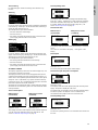
10.3 Menu INSTALLATION
10.3.1 Control mode
10.3.2 Controller
E-pumps have a factory default setting of gain (K
p
) and integral
time (T
i
). However, if the factory setting is not the optimum
setting, the gain and the integral time can be changed in the
display below.
• The gain (K
p
) can be set within the range from 0.1 to 20.
• The integral time (Ti) can be set within the range from 0.1 to
3600 s. If 3600 s is selected, the controller will function as a P
controller.
• Furthermore, it is possible to set the controller to inverse
control, meaning that if the setpoint is increased, the speed
will be reduced. In the case of inverse control, the gain (Kp)
must be set within the range from -0.1 to -20.
Without sensor
(uncontrolled)
With pressure sensor
(controlled)
Select one of the following
control modes (see fig. 18):
• Controlled
• Uncontrolled.
Select one of the following
control modes (see fig. 18):
• Controlled
• Uncontrolled.
Note
Note
If the pump is connected to a bus, the control
mode cannot be selected via the R100. See
section 15. Bus signal.

17
English (US)
The table below shows the suggested controller settings: How to set the PI controller
For most applications, the factory setting of the controller
constants K
p
and T
i
will ensure optimum pump operation.
However, in some applications an adjustment of the controller
may be needed.
Proceed as follows:
1. Increase the gain (K
p
) until the motor becomes unstable.
Instability can be seen by observing if the measured value
starts to fluctuate. Furthermore, instability is audible as the
motor starts hunting up and down.
Some systems, such as temperature controls, are slow-
reacting, meaning that it may be several minutes before the
motor becomes unstable.
2. Set the gain (K
p
) to half of the value which made the motor
unstable. This is the correct setting of the gain.
3. Reduce the integral time (T
i
) until the motor becomes
unstable.
4. Set the integral time (T
i
) to twice the value which made the
motor unstable. This is the correct setting of the integral time.
General rules of thumb:
• If the controller is too slow-reacting, increase K
p
.
• If the controller is hunting or unstable, dampen the system by
reducing K
p
or increasing T
i
.
10.3.3 External setpoint
The input for external setpoint signal can be set to different signal
types.
Select one of the following types:
•0-10 V
•0-20 mA
•4-20 mA
• Not active.
If Not active is selected, the setpoint set by means of the R100 or
on the control panel will apply.
If one of the signal types is selected, the actual setpoint is
influenced by the signal connected to the external setpoint input.
See section 14. External setpoint signal on page 27.
System/application
K
p
T
i
Heating
systems
Cooling
system
0.5 0.5
0.5
L
1)
< 16.4 ft: 0.5
L > 16.4 ft: 3
L > 32.8 ft: 5
0.5 0.5
0.5 0.5
0.5 -0.5 10 + 1.52L
0.5 10 + 1.52L
0.5 -0.5 30 + 1.52L
+2.5 100
Heating systems are systems in which an increase in pump
performance will result in a rise in temperature at the
sensor.
Cooling systems are systems in which an increase in pump
performance will result in a drop in temperature at the
sensor.
(L1) Distance in [ft] between pump and sensor
(L2) Distance in [ft] between heat exchanger and sensor
p
p
L1 [ft]
p
Q
t
L L2 [ft]
t
L2 [ft]
t
L2 [ft]

English (US)
18
10.3.4 Signal relay
Pumps of 1.5 - 10 hp have one signal relay. The factory setting of
the relay will be Fault.
Pumps of 15-30 hp have two signal relays. Signal relay 1 is
factory set to Alarm and signal relay 2 to Warning.
In one of the displays below, select in which one of three or six
operating situations the signal relay should be activated.
For further information, see section 17. Indicator lights and signal
relay on page 28.
10.3.5 Buttons on pump
The operating buttons and on the control panel can be set
to these values:
•Active
• Not active.
When set to Not active (locked), the buttons do not function. Set
the buttons to Not active if the pump should be controlled via an
external control system.
10.3.6 Pump number
A number between 1 and 64 can be allocated to the pump. In the
case of bus communication, a number must be allocated to each
pump.
10.3.7 Digital inputs
The digital inputs of the pump can be set to different functions.
Select one of the following functions:
• Min. (min. curve)
• Max. (max. curve)
• External fault
• Flow switch
• Dry running (from external sensor) (only three-phase pumps).
The selected function is activated by closing the contact between
terminals 1 and 9, 1 and 10 or 1 and 11.
See also section 13.2 Digital input on page 27.
Min.:
When the input is activated, the pump will operate according to
the min. curve.
Max.:
When the input is activated, the pump will operate according to
the max. curve.
External fault:
When the input is activated, a timer will be started. If the input is
activated for more than 5 seconds, the pump will be stopped and
a fault will be indicated. If the input is deactivated for more than 5
seconds, the fault condition will cease and the pump can only be
restarted manually by resetting the fault indication.
Flow switch:
When this function is selected, the pump will be stopped when a
connected flow switch detects low flow.
It is only possible to use this function if the pump is connected to
a pressure sensor.
If the input is activated for more than 5 seconds, the stop function
incorporated in the pump will take over. See section 10.3.8 Stop
function on page 19.
1.5 - 10 hp
• Ready
• Fault
• Operation
• Pump running (only three-phase pumps, 1.5 - 10 hp)
• Warning (only three-phase pumps, 1-10 hp).
15-30 hp 15-30 hp
• Ready
•Alarm
• Operation
• Pump running
• Warning
• Relubricate.
• Ready
•Alarm
• Operation
• Pump running
• Warning
• Relubricate.
Note
Note
Fault and Alarm cover faults resulting in Alarm.
Warning covers faults resulting in Warning.
Relubricate covers only that one individual event.
For distinction between alarm and warning, see
section 10.1.3 Fault indications on page 14.

19
English (US)
Dry running
When this function is selected, lack of inlet pressure or water
shortage can be detected. This requires the use of an accessory,
such as these:
• a Grundfos Liqtec
®
dry-running sensor
• a pressure switch installed on the suction side of a pump
• a float switch installed on the suction side of a pump.
When lack of inlet pressure or water shortage (Dry running) is
detected, the pump will be stopped. The pump cannot restart as
long as the input is activated.
10.3.8 Stop function
The stop function can be set to these values:
•Active
• Not active.
When the stop function is active, the pump will be stopped at very
low flows. The controller will stop the pump to protect the pump
as follows:
• avoid unnecessary heating of the pumped liquid
• reduce wear of the shaft seals
• reduce noise from operation.
Fig. 27 Difference between start and stop pressures (H)
ΔH is factory-set to 10 % of actual setpoint.
ΔH can be set within the range from 5 % to 30 % of actual
setpoint.
Low flow can be detected in two different ways:
1. A built-in "low-flow detection function" which functions if the
digital input is not set up for flow switch.
2. A flow switch connected to the digital input.
1. Low-flow detection function
The pump will check the flow regularly by reducing the speed for
a short time. If there is no or only a small change in pressure, this
means that there is low flow. The speed will be increased until the
stop pressure (actual setpoint + 0.5 x ΔH) is reached and the
pump will stop. When the pressure has fallen to the start pressure
(actual setpoint - 0.5 x ΔH), the pump will restart.
When restarting, the pumps will react differently according to
pump type:
Three-phase pumps
1. If the flow is higher than the low-flow limit, the pump will return
to continuous operation at constant pressure.
2. If the flow is still lower than the low-flow limit, the pump will
continue in start/stop operation. It will continue in start/stop
operation until the flow is higher than the low-flow limit; when
the flow is higher than the low-flow limit, the pump will return
to continuous operation.
2. Flow switch
When the digital input is activated for more than 5 seconds
because there is low flow, the speed will be increased until the
stop pressure (actual setpoint + 0.5 x ΔH) is reached, and the
pump will stop. When the pressure has fallen to start pressure,
the pump will start again. If there is still no flow, the pump will
quickly reach stop pressure and stop. If there is flow, the pump
will continue operating according to the setpoint.
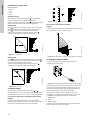
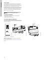
Operating conditions for the stop function
It is only possible to use the stop function if the system
incorporates a pressure sensor, a non-return valve and a
diaphragm tank.
Fig. 28 Position of the non-return valve and pressure sensor in
system with suction lift operation
Fig. 29 Position of the non-return valve and pressure sensor in
system with positive inlet pressure
TM00 7744 1896
Stop pressure
ΔH
Start pressure
H
Q
Caution
The non-return valve must always be installed
before the pressure sensor. See fig. 28 and
fig. 29.
TM03 8582 1907TM03 8583 1907
Pressure sensor
Diaphragm tank
Non-return
valve
Pump
Diaphragm tank
Pressure sensor
Pump Non-return valve

English (US)
20
Diaphragm tank
The stop function requires a diaphragm tank of a certain minimum
size. The tank must be installed immediately after the pump and
the precharge pressure must be 0.7 x actual setpoint.
Recommended diaphragm tank size:
If a diaphragm tank of the above size is installed in the system,
the factory setting of ΔH is the correct setting.
If the tank installed is too small, the pump will start and stop too
often. This can be remedied by increasing ΔH.
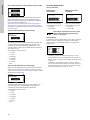
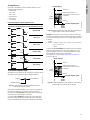
10.3.9 Flow limit for the stop function
In order to set at which flow rate the system is to go from
continuous operation at constant pressure to start/stop operation,
select among these four values of which three are preconfigured
flow limits:
•Low
•Normal
•High
•Custom.
The default setting of the pump is Normal, representing approx.
10 % of the rated flow rate of the pump.
If a lower flow limit than normal is desired or the tank size is
smaller than recommended, select Low.
If a higher flow than normal is wanted or a large tank is used, set
the limit to High.
The value Custom can be seen in R100 but it can only be set by
means of the PC Tool E-products. Custom is for customized set-
up and optimizing to the process.
Fig. 30 Three preconfigured flow limits, Low, Normal and High
10.3.10 Sensor
The setting of the sensor is only relevant in the case of controlled
operation.
Select among the following values:
• Sensor output signal
0-10 V
0-20 mA
4-20 mA,
• Unit of measurement of sensor:
bar, mbar, m, kPa, psi, ft, m³/h, m³/s, l/s, gpm, °C, °F, %,
• Sensor measuring range.
10.3.11 Duty/standby
The duty/standby function applies to two pumps connected in
parallel and controlled via GENIbus.
The duty/standby function can be set to these values:
•Active
• Not active.
When the function is set to Active, the following applies:
• Only one pump is running at a time.
• The stopped pump (standby) will automatically be cut in if the
running pump (duty) has a fault. A fault will be indicated.
• Changeover between the duty pump and the standby pump
will take place every 24 hours.
Activate the duty/standby function as follows:
1. Install and prime the two pumps according to the installation
and operating instructions supplied with the pumps.
2. Check that the power supply is connected to the first pump
according to the installation and operating instructions.
3. Use Grundfos R100 to set the duty/standby to Not active in
the installation menu.
Rated flow of
pump
[gpm (m
3
h)]
CRE pump
Typical diaphragm
tank size
[gal (liter)]
0-26
(0 - 5.9)
1s, 1, 3 2 (7.6)
27-105
(6.1 - 23.8)
5, 10, 15 4.4 (16.7)
106-176
(24.2 - 40)
20, 32 14 (53.0)
177-308
(40.2 - 70.0)
45 34 (128.7)
309-440
(70.2 - 99.9)
64, 90 62 (234.7)
441-750
(100-170)
120, 150 86 (325.5)
Note
Note
Flow limit for the stop function only works if the
system is not set up for flow switch.
TM03 9060 3307
Without sensor
(uncontrolled)
With pressure sensor
(controlled)
ΔH
Low
High
Normal
Page is loading ...
Page is loading ...
Page is loading ...
Page is loading ...
Page is loading ...
Page is loading ...
Page is loading ...
Page is loading ...
Page is loading ...
Page is loading ...
Page is loading ...
Page is loading ...
Page is loading ...
Page is loading ...
Page is loading ...
Page is loading ...
Page is loading ...
Page is loading ...
-
 1
1
-
 2
2
-
 3
3
-
 4
4
-
 5
5
-
 6
6
-
 7
7
-
 8
8
-
 9
9
-
 10
10
-
 11
11
-
 12
12
-
 13
13
-
 14
14
-
 15
15
-
 16
16
-
 17
17
-
 18
18
-
 19
19
-
 20
20
-
 21
21
-
 22
22
-
 23
23
-
 24
24
-
 25
25
-
 26
26
-
 27
27
-
 28
28
-
 29
29
-
 30
30
-
 31
31
-
 32
32
-
 33
33
-
 34
34
-
 35
35
-
 36
36
-
 37
37
-
 38
38


Ask a question and I''ll find the answer in the document
Finding information in a document is now easier with AI
Related papers
-
Grundfos CRE Installation And Operating Instructions Manual
-
Grundfos NBGE Series Installation And Operating Instructions Manual
-
-
-
-
-
-
-
Grundfos TPE 2000 Series Installation And Operating Instructions Manual
-
Other documents
-
Amino R100 User guide
-
Roberts BPR1( Rev.1) User guide
-
BIGBIG WON R100 Operating instructions
-
OJ Electronics OJ-DV-Relay-Module Operating instructions
-
Danfoss KE14001 Valve Drive Amplifier Installation guide
-
 BAFANG CR X10T.250.FC Owner's manual
-
-
 IONODES ION-R100 User manual
-
Casio VR-100 Product information
-
Franklin 5870206300 User manual

