Page is loading ...

INSTALLATION GUIDE
version 1.3
SCS2 Multi-Line
Digital Receiver
version 1.3

TABLE OF CONTENTS
INTRODUCTION 1
SCS2-300 ..............................................................................................1
SCS2-200 ..............................................................................................1
Supervision ..........................................................................................1
Compatibility ......................................................................................1
SCS2-300 Outputs/Inputs .................................................................... 1
System Overview.................................................................................1
Virtual Receiver Architecture ............................................................2
Number of Line Cards Supported .......................................................2
Approvals .............................................................................................2
SCS2 Backplane Connection Diagram .................................................3
Connections for SCS2-200 Line Card Expansion .................................3
SCS2 UPS Connection Diagram............................................................4
Quick Start 5
Receiver Setup and Operation Without Programming.......................5
Installation 6
Mounting the Receiver........................................................................6
Printer Connections ............................................................................6
Computer Connections ....................................................................... 6
Telephone Line Connections ..............................................................6
Grounding ............................................................................................6
Power Supply....................................................................................... 6
Battery Charging Current ...................................................................6
SCS2-200 Digital Receiver Line Card 7
General Information ...........................................................................7
SCS2-200 Features...............................................................................7
Installation ..........................................................................................7
SCS2-200 Controls ...............................................................................7
SCS2-200 Operating Mode 8
SCS2-200 Standby Mode ......................................................................8
SCS2-200 Cold Startup ......................................................................10
Communications in Progress ............................................................. 10
Profiles 11
Static Options....................................................................................11
Default Dynamic Options ..................................................................12
SCS2-200 Communication Formats 18
Common Formats .............................................................................. 18
DMP DTMF Formats ........................................................................... 18
Ademco Contact ID ...........................................................................18
Ademco Express ................................................................................18
Ademco Super Fast (High Speed Format) ....................................... 19
DMP FSK .............................................................................................19
FBI Super Fast Format.......................................................................19
ITI Format..........................................................................................20
Modem II, Modem IIE, Modem IIIa² and BFSK Formats .................... 21
SIA FSK ...............................................................................................21
Silent Knight FSK1, FSK2................................................................... 21
Silent Knight FSK2 Protocol ..............................................................21
Sescoa Super Speed ..........................................................................22
SCS2-200 Predefined Library Decoding and
Event Codes Table ............................................................................ 23
SCS2-300 – Central Processing Module 24
General Information .........................................................................24
Features ............................................................................................24
SCS2-300 Controls .............................................................................24
SCS2-300 Operating Mode .................................................................25
Message Priorities .............................................................................30
SCS2-300 Utility Modes ..................................................................... 31
SCS2-300 EPROM Programming .........................................................33
Automation Protocols 33
Data Byte Protocol:...........................................................................33
Acknowledgment of the Signal.........................................................33
Appendix A: SCS2-200 Communication Formats 34
Appendix B: ASCII Character Chart 35
Appendix C: Decimal - Hex - Binary Conversion Chart 36
Appendix D: Printer Words - Options [60] - [6F] 37
Appendix E: Default Static Options 38
Appendix F: Default Dynamic Options 39
Appendix G: Event Code Classifications 40

1
INTRODUCTION
The SCS2 is a multi-line, multi-format digital receiver for
commercial fire and burglary. The basic unit consists of up
to 15 individual line card modules (SCS2-200) and 30 telco
lines connected to a SCS2-300. The SCS2 can decode a variety
of popular and widely used communication formats. Refer
to Appendix A, SCS2-200 Communication Formats for a list
of the available communication protocols.
The SCS2’s real-time clock and calendar stamps all information
received with the time and date, and all information can be
printed and/or forwarded to a computer. To ensure security,
adjustment of the clock, calendar and other programming is
password-protected.
SCS2-300
The SCS2-300 Central Processing Module oversees operation
of the line cards. Along with its built-in keypad and LCD
message screen, the SCS2-300 features one parallel printer
port, and two COM Ports.
SCS2-200
Each SCS2-200 module can monitor two telephone lines. The
line card module is equipped with a 256-event non-volatile
memory buffer to record events and corresponding telephone
numbers. Caller Source capability is built-in and telephone
numbers can be printed out, sent to automation and stored
in memory. Events and information stored in memory can be
printed at any time. Each line card also features flash EPROM
uploads through the Debug port for software upgrades or
options programming.
SUPERVISION
The standby battery voltage and connections are supervised.
The line cards are also continuously supervised to ensure
uninterrupted communication with the SCS2-300. Any trouble
conditions are reported on the LCD screens and sent to the
printer and the computer.
The SCS2-200 line card module also verifies communications
with the SCS2-300. In the event of a malfunction, the operator
will be advised with a visual indication and the line cards will
continue to function. Each line card will continue to receive
information.
The printer is supervised for loss of power, off-line, paper
out and other trouble conditions. The communication link to
the computer through the RS-232 port is monitored by the
supervisory “heartbeat” test transmissions.
COMPATIBILITY
Central station automation software packages such as
M.A.S., DICE, SIMSII, S.I.S., GENESIS and MICROKEY
support the SCS2 DMP interface. Compatibility with the automation
software in a system used at a central station is intended to
be handled under a separate UL 1981 software package and/
or site certification evaluation.
SCS2-300 OUTPUTS/INPUTS
The SCS2-300 features three switched-negative outputs. One
output labeled “OPTION” has a corresponding LED on the
SCS2-300 front panel; the factory default programming slowly
flashes the OPTION LED when the “OPTION” output is activated.
Switched negative outputs are also provided for the
Acknowledge and Trouble LEDs.
SYSTEM OVERVIEW
• Patented Caller Identification (Call Display) capability
• Patent pending DNIS identification
• Battery backed up RAM on each SCS2-200 line card
module for programming and event buffers.
• Fast communication between line cards and SCS2-300
• Flash upload for software upgrades
• Up to 64 different options set (profiles per line)
• Patent pending Virtual configurations
• 3/1, 4/2 formats with or without parity, 4/1 without parity
at 10, 14, 20, or 40 Baud
• 4/1, 4/2, 4/3, and 4/3 with checksum DTMF formats
• Optional* formats: 3-2, 4/1,4/2 extended
• Contact ID (DTMF) format
• Super Fast or High Speed DTMF format, with or
without parity
• DTMF 4/1 Express format optional*, 4/2 Express format
• Westec
• FBI Super Fast format with or without parity
• RADIONICS Modem II, Modem IIE, Modem IIIa
2
and
BFSK formats
• SIA format: 110 and 300 Baud, tone and data
acknowledgment
• SK FSK1, FSK2
• Any handshake frequencies by increment of 100 Hz
from 300 Hz to 3400 HZ, Dual Tone, SIA FSK, Modem
IIx, Double Dual Tone and ITI selected by configuration
commands.
• Up to 8 different handshakes per profile with individual
duration control.
• Large, easy to read 2-line, 16-characters-per-line, Liquid
Crystal Display screen
• All modules function individually to help ensure
uninterrupted operation during hardware or software
upgrades
• Inputs on SCS2-300 for UPS supervisory
• 30 lines maximum per receiver
• 256-event memory buffer on each individual line card
• Real-time clock
• SCS2-300 features 16-bit microcontroller
• 1 parallel printer port and 2 serial RS-232 ports
• Programmable serial port configurations
• Programmable system functions: computer and printer
• Fast transmission of multiple alarms to the computer
and printer to ensure operator’s quick response
• Continuous verification of the computer-receiver links
with the “heartbeat” function
• Switched-negative outputs on SCS2-300 (special
applications)
• AC-lost detection and standby battery supervision
• Low battery detection and automatic low battery disconnect
to prevent deep-discharge damage to battery
• Operator Acknowledge option
• Telephone line supervision and reporting
*All formats noted as optional are selected using configuration
commands.

2
VIRTUAL RECEIVER ARCHITECTURE
The most novel feature of the SCS2-200 is its ability to use
the telephone company information delivered as DNIS (Dialed
Number Information Service) or Caller ID. This allows the
DMP Format Expert System to handle on the fly each received
call. With this feature, dedicated line pool hardware is
eliminated. Instead, the DNIS or Caller ID information allows
dynamic options that set up virtual line pools to identify
security formats and extend account numbers.
Standard DNIS is supported up to 10 digits. Each dialed
number should be assigned to a virtual receiver. Multiple
Caller ID numbers can be assigned to a single virtual receiver.
Each dialed number would formerly have been a line pool
on conventional line cards.
NUMBER OF LINE CARDS SUPPORTED
The system will support a maximum of 15 line card modules
concurrently connected.
APPROVALS
Agency Listings
• UL 864 Control Units for Fire-Protective Signaling
Systems
• UL 1610 Central Station Burglar Alarm Units
This equipment should be installed in accordance with the
requirements of NFPA72, NFPA70, UL827 and the local
authority having jurisdiction.
UL MANUAL MODE
For UL manual mode, each event will activate the internal
buzzer to be acknowledged manually. Each event will also
be sent automatically to the connected printer.
For Central Station applications, the signaling performance of
each DACT (Digital Alarm Communication Transmitter) shall
be manually tracked. Failure to receive a signal from a DACT
over a 24 hour period shall be handled as a trouble signal.

3
P
6
P
5
P4 P2
R13
R11
R4
R6
R7
R12
P
6
P
5
P4 P2
R13
R11
R4
R6
R7
R12
P
6
MV3 MV2
P
5
P4 P2
R13
R11
R4
R6
R7
R12
REFER TO SCS2-430 POWER
CONNECTIONS
REFER TO SCS2-430 CONNECTIONS
SCS2-430
SCS2
SUR-GARD LTD.
SCS2
SCS2
SUR-GARD SECURITY SYSTEMS LTD.
SUR-GARD SECURITY SYSTEMS LTD.
SUR-GARD SECURITY SYSTEMS LTD.
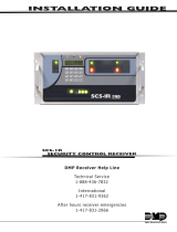
SCS2 BACKPLANE CONNECTION DIAGRAM
CONNECTIONS FOR SCS2-420 LINE CARD EXPANSION
NEXT
MODULE
NEXT
MODULE
P
6
MV3 MV2
P
5
P4 P2
R13
R11
R4
R6
R7
R12
Battery
12V Rechargeable
lead-acid
35Ah
Transformer
16 V
AC
, 175 VA
REFER TO SCS2-430 POWER
CONNECTIONS
REFER TO SCS2-430 CONNECTIONS
SCS2-430
SCS2
SCS2-430 POWER CONNECTIONS
SCS2-430 CONNECTIONS
Not used on
SCS2-300
Not used on
SCS2-300
SUR-GARD SECURITY SYSTEMS LTD.
SUR-GARD LTD.

4
SCS2 UPS CONNECTION DIAGRAM
REFER TO SCS2-430 POWER
CONNECTIONS
REFER TO SCS2-430 CONNECTIONS
SCS2
SCS2-430 POWER CONNECTIONS
SCS2-430 CONNECTIONS
Not used on
SCS2-300
Not used on
SCS2-300

5
QUICK START
Receiver Setup and Operation Without
Programming
UNPACKING
Carefully unpack the receiver and inspect for shipping damage.
If there is any apparent damage, notify the carrier immediately.
BENCH TESTING
It is suggested that the receiver be tested before actual
installation; becoming familiar with the connections and setup
of the unit on the workbench will make final installation more
straightforward.
The following items are required:
• 16V
AC, 175VA transformer
• 2 telephone lines
• One or more dialers or digital dialer control panels
Dialers and control panels using an optocoupler phone line
interface will require a connection method providing a DC
current for direct connection testing.
POWER UP
When power is applied, the receiver will beep and will
indicate any trouble conditions on the LCD message screen.
If the line cards do not have telephone lines connected, the
SCS2-200 modules will beep and their “Line Fault” LEDs will
FLASH.
Press the flashing [ACK] button to silence the buzzer. If
there is no computer or printer connected, a trouble message
will be displayed on the SCS2-300 LCD and the “ACK” light
will FLASH. Press the [ACK] button to silence the SCS2-300
buzzer.
OPERATION WITH DEFAULT PROGRAMMING
Without any changes to the factory default programming,
the receiver operates as follows:
• Answers incoming calls on the first ring
• Sends SIA FSK as the first handshake
• Sends 1400 Hz as the second handshake
• Sends double dual tone as the third handshake
• Sends 2300 HZ tone as the fourth handshake
• Sends Modem II tone as the fifth handshake
• Sends ITI, Modem IIE, Modem IIIa2 tone as sixth handshake
• The following formats can be manually selected: 3/2, 4/1
express, 4/2 extended, 4/2 checksum and 3/1 checksum.
Signals can be displayed on the debug output as they are received.
The signals are then sent to the parallel printer and computer
connected to serial port COM1. The default event codes described
in the “SCS2-200 Library Decoding and Event Codes Table” will
be used with the DMP Automation Communication Protocol to
send signals to the computer, if connected.
If a computer is not connected, press the [ACK] button on
the SCS2-300 module to silence the buzzer.
SERIAL LAPLINK CABLE FOR DEBUG/CONSOLE
For Debug/Console data transfer between a PC and the SCS2-
200, a serial data transfer cable is used to connect either
the DB9 male or DB25 male serial ports on a computer to
the DB9 male serial (Debug/Console) port on the SCS2-200.
Serial Laplink Cable
from DB9 from DB25 to DB9 to DB25 Signal
2 3 2 3 Receive - Transmit
3 2 3 2 Transmit - Receive
4 20 6 6 DTR - DSR
5 7 7 5 Ground - Ground
6 6 20 4 DSR - DTR
7 4 5 8 RTS - CTS
8 5 4 7 CTS - RTS
DEBUG OUPUT
The debug output is another means of accessing the line
card’s programmed options and diagnostics features. A null
modem cable is required to connect by serial communication.
DEBUG CABLE CONNECTIVITY
Connect the female DB-9 connector to the serial port of a
computer.
DEBUG SOFTWARE SETUP
Using WIN9x, point and click on the “START” button. Access
“Programs” -> “Accessories” -> “HyperTerminal.” Once in
the HyperTerminal window, point and click on “Hypertrm.exe”
icon.
A connection description window should appear. A prompt
should appear on the “Name” category. Type a name. Point
and click on “OK."
A phone number window should appear. Choose the “direct
to” COM port required for connection and point and click
on “OK”.
COM port properties windows should appear. The configuration
should be :
• Bits per second: 19200
• Data bits: 8
• Parity: None
• Stop bits: 1
• Flow control: None
Point and click on the “OK” button after setting the
configuration.
The HyperTerminal window should appear. Press any button.
The debug menu will be displayed.
BUTTON COMMANDS
C Cold boot
D This button will initiate the download of a file to the line
card.
O This button will enable the user to dump the current
programmed options of the line card or set an option to
a particular value.
V To view software version information
DOWNLOADING STEPS
Press the “D” button to initiate downloading of the binary
file. The HyperTerminal will display:
Ready to download.
CCCC
Point and click at “Transfer” on the HyperTerminal menu
and access the “Send File” category (you also have right-
click access with the mouse). The “Send File” window should
appear. Change the protocol to “X-modem” and place the
correct path and file name of the binary file to be uploaded.
Point and click on the “Send” button and the downloading
status window should appear.
The line card will restart automatically after a successful
upload.

6
INSTALLATION
MOUNTING THE RECEIVER
Install the SCS2 in a closed 19"/48cm rack or cabinet with
a locking rear access door. Cover all unused spaces with
blank metal plates. The LCD screens on the receiver are
designed to be viewed below eye level. If the unit must be
mounted where the screens are above eye level, angle the
unit downwards to improve visibility. The following items
can be supplied for a complete installation:
Stand-up Unit (61.25"/1.55cm tall up to 30 telephone lines)
Part # MLR2-CL
• Rack
• Door with lock and ventilation
• Blank plates 21"/53cm (2)
• Blank plate 5.25"/13.3cm (3)
• Screws
• Washers
• Clipnuts
• FROST 16V/175VA transformer
P/N FT3304
• AC utility box
• AC cable clamps (2)
• 8'/2.4m battery cables
• 3-Gauge conductor AC cable
• Secondary non-replaceable fuse, 15A, 125 V
AC
NOTE: If 30 telephone lines are not used, cover each un-
used location with a blank plate.
Desk-mount Unit (28"/71cm tall up to 14 telephone lines)
Part # MLR2-CM
• Rack
• Louvered door back plate
• Blank Plate 1.75"]
• Back Plate 7"/17.8cm
• Blank Plates 5.25 (4)
• Screws
• Washers
• Clipnuts
• FROST 16V/175VA
• AC utility box
• AC cable clamp for 3/8"/1cm cable
• 8'/2.4m battery cable
• 18 gauge 3-conductor AC cable
• Secondary non-replaceable fuse, 15A, 125 V
AC
NOTE: If 18 telephone lines are not used, cover each unused
location with a blank plate.
PRINTER CONNECTIONS
Connect the parallel printer to the SCS2 printer output port
using a standard parallel printer cable.
For UL Listed applications, the following UL Listed print-
ers can be used with the SCS2:
• DMP CPU-1150
• DMP CPU DMP-206
• DMP SCS-PTR
IMPORTANT: Do not use a printer cable that has only 1
common ground wire.
COMPUTER CONNECTIONS
Connect the computer to the SCS2 RS-232 port using a serial
cable to COM1.
IMPORTANT: Do not use a null modem cable.
Receiver RS-232 Computer RS-232 Computer RS-232
25-pin connector 25-pin connector 9-pin connector
11
223
332
775
TELEPHONE LINE CONNECTIONS
With 6-pin modular cables, connect each line module jack
(line 1 or 2) to its corresponding telephone line.
GROUNDING
For maximum resistance to static and electrical noise, the
19"/48cm rack frame should be connected to earth ground
through the AC utility box.
POWER SUPPLY
Ensure that all electrical connections are made correctly. After
verifying all connections, connect the RED and BLACK leads to
a 12V
DC sealed rechargeable battery. Be sure to observe polarity
when connecting the battery. When the battery is connected,
test the system under battery power only. CAUTION: Connecting
a positive (+) terminal to a negative (-) terminal may cause a
fire and possibly serious personal harm.
For 4-hour standby a 12-volt 35 Ah rechargeable battery
should be used in conjunction with an engine-driven power
generator.
BATTERY CHARGING CURRENT
The maximum battery charging current is factory set at 1A.
DB-25 to DB-25
DB-25 to DB-9
SCS2

7
SCS2-200 DIGITAL RECEIVER
LINE CARD
The SCS2-200 acts as an interface between the digital alarm
transmitter and the SCS2-300. Different communication formats
can be used to transmit the information.
The main functions of the line cards are to continuously
monitor the telephone line, receive calls from digital dialers
or control panels, and to report alarms to the SCS2-300. In
addition, if a line card is unable to communicate with the
SCS2-300, each line card is capable of functioning
independently. Each line card can record 256 different alarm
messages and 255 Caller-ID telephone numbers.
GENERAL INFORMATION
The receiver is capable of processing signals from digital
communicators in a variety of formats. The type of signal
(alarm, trouble, restore, cancel and so on) can be printed.
SCS2-200 FEATURES
• Operator selection of communication formats and
handshake priority
• 64 profiles per line card, up to 30 line pools.
• Flash Download for software upgrades.
• Records up to 256 messages.
• Records up to 256 Caller ID phone numbers. This
feature helps to locate and identify the source of the
device in communication and assists in troubleshooting.
• Multiple alarms are forwarded to the computer and
printer through the SCS2-300 with minimum delay
• The SCS2-200 monitors the telephone line connection,
and line faults will result in reports to the computer
and the printer
• SCS2-200 automatically goes into standalone mode in
case of SCS2-300 failure
• “Watchdog” timer continually monitors receiver operation
• “Cold boot” option allows receiver’s configuration to be
reset to factory default programming
• DSP processing to reduce data receiving errors, and to
help for weak and noisy signals
• Gain boost available to amplify weak signals
• Serial link for troubleshooting and easy software
upgrade
SCS2-200 CONTROLS
Each SCS2-200 Module features 2 line cards. The LEDs and
push buttons on the left side and the upper LCD are for Line
Card 1. The LEDs and push buttons on the right side and the
lower LCD are for Line Card 2.
Momentarily depressing and releasing a button will register
as a single input or keystroke. Pressing and holding a button
for approximately 1 second will register as a repeating input
or keystroke. For example, to quickly scroll through a list of
items, you press and hold the appropriate button, rather
than pressing the button repeatedly.
LCD (Liquid Crystal Display)
Displays incoming data, programming and other information.
The display is backlit for visibility in low light environments.
AUDIO
The “Audio” light comes ON when the receiver is in Audio
mode. When ON, “listen-in” or “2-Way Audio” is in use. The
“Audio” light will automatically turn OFF at the end of the
timed period or when the [CANCEL] button is pressed.
LINE FAULT
The “Line Fault” light will come ON if the telephone line is
disconnected. The “Line Fault” light will turn OFF automatically
when the telephone line is restored.
MESSAGE ERROR
The “Message Error” light will come ON when faulty data is
received (for example, if the round pair does not match, or if
the checksum is incorrect). Press the [ACK] button to acknowledge
the error; the “Message Error” light will be shut OFF.
[ACK/FUNCTION] BUTTON
Press this button to acknowledge an alarm in emergency
manual mode. In the normal mode, press this button to
access the line card menu.
ALARM
The “Alarm” light is located inside the [ACK/FUNCTION] button.
The “Alarm” light will flash if an alarm is received. The
“Alarm” light will be shut OFF when the alarm is successfully
communicated to the SCS2-300, or when the operator
acknowledges the alarm by pressing the [ACK/FUNCTION] button.
CANCEL SELECT
While on-line, press this button to drop the line. In normal
mode, press this button to select the current item.
WATCHDOG
The "Watchdog" light will FLASH once every 4 seconds to
indicate that line card operation is being monitored.

8
SCS2-200 Operating Mode
SCS2-200 STANDBY MODE
With the line card installed, apply power to the unit. This
message will be displayed briefly on the top LCD:
INITIALIZING
CONTRAST LOADING
Next, the following message will be displayed on each line
card in turn, starting with line card 1:
PRESS ACK+SELECT
TO COLDBOOT
The cold booting procedure is covered in detail below.
The LCDs will then display:
INITIALIZING
CONTRAST LOADING
During this time, the line cards will load default options and
code, and perform a low-level diagnostic to determine the
status of the system.
Once the line cards are ready, they will display a message
similar to the following:
SCS2-200-Line #D
<<-Line Fault->>
After these startup messages, the line card monitors the
telephone line and the SCS2-300.
LINE FAULT
The SCS2-200 verifies the telephone line voltage every 10
seconds. The “Line Fault” light will come ON after two
successive line verifications indicate irregular telephone line
voltage. This message will be displayed:
SCS2-200-Line #D
<<-Line Fault->>
If the Line Check option is enabled, the following information
will be transmitted to the printer and computer:
Printer: L01- 0000-PHONE-LINE-TROUBLETIME:DATE
(printer option set to 03)
Computer: 0RRL[#0000 | NLTRRLL]
NOTE: The first RRL is subject to the line card length
option. The second RRL is the receiver and line card number,
both in HEX.
If the Line Check option is disabled, the SCS2-200 will not
send the report to the printer or computer. Refer to “SCS2-
200 Programmable Features” for information on enabling
the Line Check option.
When the line condition returns to normal, the “Line Fault”
LED will be shut OFF.
If the Line Check option is enabled and the telephone line
returns to normal, the following information will be transmitted
to the printer and computer:
Printer: L01- 0000-PHONE-LINE-RESTORALTIME:DATE
Computer: 0RRL[#0000 | NLRRRLL]
NOTE: The first RRL is subject to the line card length option.
The second RRLL is the receiver and line card number,
both in HEX.
SCS2-300 ERROR; DISPLAY ALARM MESSAGES
If the SCS2-200 cannot detect SCS2-300 polling and there
are no alarm events in the event buffer, this message will
be displayed:
SCS2-200-Line #D
<<-SCS2-300 ERROR->>
If alarm messages cannot be sent to the SCS2-300 because
of the error, the SCS2-200 will display the oldest message
which has not been manually acknowledged. The “Alarm”
light will FLASH and the sounder will beep if the “Mute Buzzer”
option is programmed as [00], [02] or [03].
When a SCS2-300 error is present, each alarm must be manually
acknowledged. Press the [ACK/FUNCTION] button to acknowledge
the alarm and silence the line card sounder. If several alarms
have been received but cannot be sent to the SCS2-300, they
will have to be individually acknowledged; when all alarms are
acknowledged, the line card sounder will be silenced.
Up to 128 alarm messages for the printer and computer will
be retained in the SCS2-300 event buffer. When the event
buffer is full, the oldest messages will be deleted as new
events are recorded.
When the SCS2-300 error condition is corrected, the alarm
messages in the event buffer will be transmitted to the SCS2-300.
KEEP LAST ALARM MESSAGE
The SCS2-200 may be programmed to leave the last alarm
message on the display screen until a new message is received.
A typical alarm message is shown below:
0000-PHONE LINE
TROUBLE 28
“0000” is the “internal” account code.
“28” is the event’s location in the event buffer.
STANDBY MODE
When the line card is operating normally, this message will
be displayed:
SCS2-200-Line #D
Unit in Standby
LINE CARD MENU MODE
When the unit is not on line, pressing the [ACK/FUNCTION]
button will display the first function menu:
PRINTER BUFFER
ACK:menu SEL:sel

9
Press the [ACK] button to scroll through the menu items. Press
the [SELECT] button to select the function displayed on the LCD
screen. When a function is selected, press [ACK] and [SELECT]
together to exit from the Menu mode. The SCS2-200 will
automatically exit from the Menu mode if no keys are pressed
for 30 seconds.
The following functions are available in the line card
Menu mode:
• Display Printer Alarm Buffer
• Display Line Card Configuration
• Display Program Version
• Adjust LCD Contrast
• Adjust Backlight
DISPLAY PRINTER AND CALLER ID ALARM BUFFER
PRINTER BUFFER
ACK:menu SEL:sel
With this message displayed, press the [SELECT] button; the
most recent alarm message will be displayed. If Option [12]
CALLER SOURCE is selected, the corresponding Caller
Identification will also be displayed.
Press the [SELECT] button to scroll backwards through alarm
messages; press the [ACK] button to scroll forward through
alarm messages.
Press the [ACK] button to display the alarm message:
3576-312
Alarm 001
“3576” is the Account Code.
In this example, a 4/3 communication format is used.
“3” indicates an alarm, while “12” is the zone number.
“Alarm” indicates an alarm.
“001” is the event’s location in the event buffer.
The event buffer can record up to 256 alarm messages and
Caller Identifications. To print these messages, a print
command can be sent from the SCS2-300; refer to “SCS2-
300 Utility Mode” for information.
If no Caller Identification data was received from the telephone
company, the following message will be displayed when the
[ACK] button is pressed to display the Caller Identification
screen:
1234 UnknownCall
If the Caller Identification is sent but with no telephone
number, one of these messages could be displayed:
1234 PRIVATE NO
1234 UNAVAILABLE
If Option [12] is disabled, the Caller Identification feature will
be bypassed; only the alarm messages will be displayed.
Press [ACK] and [SELECT] together to return to the Standby
mode. If no keys are pressed, the SCS2-200 will automatically
return to the Standby mode after 30 seconds.
DISPLAY OPTIONS
DISPLAY OPTIONS
ACK:menu SEL:sel
With this message displayed, press the [SELECT] button; the
current Option Configuration will be displayed. Shown
below is the first screen you will see, representing profile
0. Use the ACK button to scroll through all 64 profiles (0-
63).
Select Profile 0
Ack: up SEL: sel
Press [ACK] and [SELECT] together to return to the
Standby mode.
options display
and description
DISPLAY PROGRAM VERSION
PROGRAM VERSION
ACK:menu SEL:sel
With this message displayed, press the [SELECT] button; the
date and the software version number will be displayed as
shown below:
SG-SCS2-200 V1.30
Jan 19,2001
Press [ACK] and [SELECT] together to return to the Standby
mode.
ADJUST LCD CONTRAST
Adjust CONTRAST
ACK:menu SEL:sel
With this message displayed, press the [SELECT] button to
adjust the LCD screen’s contrast. When the [SELECT] button
is pressed, this message will be displayed:
Adjust CONTRAST
....
Press the [ACK] button to increase the contrast; press the
[SELECT] button to reduce the contrast. The display will
indicate the contrast level on the second line.
Press [ACK] and [SELECT] together to return to the Standby
mode.
ADJUST BACKLIGHT
ADJUST BACKLIGHT
ACK: up SEL: down
The [ACK] button is used to brighten the backlighting and
the [SELECT] button is used to darken it.

10
SCS2-200 COLD STARTUP
From HyperTerminal, press “C” to perform a cold boot and
select which channel to cold boot, either 1 or 2. The
following will appear on the display:
COLD BOOTING
Channel X
X = 1 or 2
[ACK] and [SELECT] must be presssed on power up to
initiate cold boot.
COLD BOOT?
ACK: yes SEL: no
CHANGE LC NUMBER?
ACK: yes SEL: no
LINECARDNUMBER:OE
ACK: up SEL:down
COMMUNICATIONS IN PROGRESS
Data Reception
During data reception, a message similar to this will be displayed:
In Communication
1234 56
If valid Caller Identification information is received, a message
similar to this will be displayed:
TEL:15145551212
1234 56
The SCS2-200 decodes all information received and stores
the information in its event buffer. When a valid signal is
received, the SCS2-200 sends a kissoff signal and transmits
the decoded alarm signal to the computer and then to the
printer through the SCS2-300.
Options [1D] and [1E] can be adjusted to allow the SCS2-200
to compensate for weak signals or noisy telephone lines;
refer to “SCS2-200 Programmable Features” for information
on programming these options.
The SCS2-200 will send each message it receives to the
printer for review by the system operator. Two messages
may be sent to the printer to indicate reception problems:
“Invalid Report” and “Communication Fail”.
INVALID REPORT MESSAGE
When this problem is encountered, the following information
is transmitted to the printer and the computer:
Printer: L01- 0000-INVALID REPORT TIME:DATE
Computer: 0RRL[#0000 | NYNRRLL]
NOTE: The first RRL is subject to the line card length
option.The second RRLL is the receiver and line card
number, both in HEX.
This output for account code “0000” indicates that data has
been received, but is not valid (for example, there are
unmatched rounds or the wrong parity). The following is an
example of faulty data received by the SCS2-200, and the
printer output generated:
Round Data Received Printer Output
1st 123456 [No printout]
2nd 123446 ?1234?56 Invalid Report
?1234?46 Invalid Report
3rd 123356 ?1233?56 Invalid Report
4th 123456 ?1234?56 Invalid Report
5th 123346 ?1233?46 Invalid Report
?????10 Invalid Report
NOTE: There is only 1 invalid report at the end of a call.
COMMUNICATION FAIL
When this problem is encountered, the following information
is transmitted to the printer and the computer:
Printer: L01- 0000-COMMUNICATION FAIL TIME:DATE
Computer: 0RRL[#0000 | NYCRRLL]
NOTE: The first RRL is subject to the line card length
option. The second RRLL is the receiver and line card
number, both in HEX.
This output indicates that a call was received, but no data was
detected. The call may have been a wrong number, or the
calling control panel was unable to connect with the receiver’s
handshake.
CALLER ID
If an Invalid Report or Communication Fail occurs, and
Caller ID is enabled, the printer messages will be similar to
the following:
Fault Data: “??????10 5551212”
Fault Call: “??????40 5551212”
Note that “?” represents the missing data; “5551212” represents
the originating telephone number.
Stopping Data Reception Manually
To cancel communications between the SCS2-200 line card
and the calling control panel, press the [CANCEL] button.
Pressing the [CANCEL] button will hang up the line. This
feature can be used to hang up on a control panel that is
repeatedly sending alarms.

11
PROFILES
The SCS2-200 will load unique “profiles” in order to effectively
communicate with control panels. A profile is a set of pre-pro-
grammed line card options unique for a particular “Calling ID
Number” or DNIS number. The “Calling id” or “DNIS” will point to a
particular profile, which will then be loaded into the line card at the
beginning of each call.
Each SCS2-200 can have a maximum of 64 profiles. To change the
options for a particular profile, utility software is provided. This
software will allow the user /operator to edit the profiles.
STATIC OPTIONS
Option [01]: Line Card Number
The Line Card Number provides a virtual identification code
for each SCS2-200 module. Hexadecimal numbers “01” to
“1E” can be programmed in Option [01] to identify line
cards.
[Defaults are 0D and 0E]
Option [02]: Line Card Number Length
This option is used to determine how many digits from the
line card number will be sent to the output. You also have
the option of displaying the number in hex or decimal.
Program option 02 with one of the following:
01 Send only one hex digit to the printer or computer
output (If you have a 2 digit line card number, only
the last digit will be sent to the output).
02 Send 2 hex digit line card number to the output.
03 Send 3 hex digit line card number to the output (leading
zeros will be inserted prior to the line card number).
0A Send 2 digits receiver number in decimal. 3 digits line
number in decimal.
0D Send 2 digits receiver number as programmed. Send
3 digits line card number in decimal.
0E Send 2 digits receiver number in Hex. Send 1 digit
line card number as follows:
Line Card # Send
1..F 1..F
10..1E G..U
NOTE: When using the SCS2-200, the Line Card Number
Length option should always correspond to the number
of DNIS digits being received.
For example, if 5 digits are being received then the Line
Card Number Length Option should be programmed to 3
so that 1RRLLL would be overwritten by the 5 digits of
DNIS to become 1ddddd. [Default is 0E]
Option [04]: 2-Way Audio Activation Time
Option [04] determines how long, in 10-second increments,
the 2-Way Audio function will be active once it is initiated.
At the end of this time, the line card will hang up the line.
Program a value from “01” to “FF” for 10 to 2550 seconds.
Three minutes (set option 04 to 12) is the recommended
length of time for the 2-Way Audio activation time.
To disable the 2-Way Audio feature, program Option [04]
as “00”.
NOTE: For UL Listed installations program time maximum
20 seconds.
[Default is 00]
Option [05]: Pre-Handshake Delay
When the line card seizes the line, it will wait the time
programmed at option [05], then send the first handshake.
The time programmed (hex) at this location will be multiplied
by 100 ms – e.g., 100 ms, 200 ms etc.
The default setting is 0A, for 1 second.
NOTE: If DNIS is used, this time will not start until DNIS
is received.
[Default is 00]
Option [0F]: Mute Buzzer Option
Operation of the line card’s buzzer may be programmed as
follows:
00 Buzzer sounds for line fault, SCS2-300 error, or if an
alarm occurs during a SCS2-300 error
01 Buzzer does not sound for any event
02 Buzzer sounds for audio, line fault, SCS2-300 error,
or if an alarm occurs during a SCS2-300 error
03 Buzzer sounds for all status change conditions
[Default is 00]
Option [10]: Keep Last Message On
To have the last alarm message retained on the SCS2-200
display, enable this option with a setting of 01.
Option [11]: Hook-flash Enable/Disable
Enables or disables ability to hook-flash the phone lines and
determines its duration in increments of 10 ms.
If programmed as 00, the option is disabled. If set to anything
else, you multiply the decimal equivalent of the hex value
by 10ms and that is the duration.
For example, if a hook-flash time of 500 ms is wanted, program
option [11] to 32 hex. 500 ms/10=50, 50 Dec=32 hex.
[Default is 00]
Option [12]: Caller Source Selection
Option [12] allows the line card to receive Caller ID data or
DNIS that is transmitted after the first ring on the telephone
line.
The appropriate service must be available and requested
from the telephone company for this feature to be operational.
00 Disabled
01 North American CID
• Private Call: An anonymous indication is received
instead of the originating telephone number
• No call no.: An out-of-area or unavailable indication is
received instead of the originating telephone number
• Unknown Call: The originating telephone number has
not been received or was not transmitted
02 British Caller ID (BABT hardware required)
04 – 0A Receive 04 –10 DTMF DNIS digits [Default is 00]
Option [13]: Caller Source to SG Computer
Option [13] allows the transmission of the Caller Identification
or DNIS, to the computer output.
Program Option [13] as one of the following:
00 Do not send to the computer
01 4RRL protocol: send to the computer using North
American Caller ID protocol
05 4RRL protocol: send to the computer using North
American Caller ID protocol sending calling name to
the computer if available.
NOTE: Option [12] must be enabled.
[Default is 00]

12
Option [14]: Caller Source to printer
Option [14] allows the transmission of the Caller Identification
or DNIS, to the printer output.
Program Option [14] as one of the following:
00 Do not send Caller Source to the printer
01 Send Caller ID to the printer
05 Send Caller Name and Caller ID to the printer if available.
Each alarm will print an extra line, printing the Caller Source.
NOTE: Option [12] must be enabled.
[Default is 00]
Option [19]: Fault Data Counter
This option allows the line card to control the rate at which
fault call messages are generated.
00 Generate a fault call message for every 10 fault calls
received
01 Generate a fault call message for every fault call
received
[Default is 00]
Option [1A]: DNIS Sensitivity
NOTE: Do not change this option unless specified by a
DMP technician.
Option [1C]: Busy Out
This option allows the line card to immediately seize the phone
line in case of loss of communication with the SCS2 checksum
error after download.
Program Option [1C] with one of the following:
00 The line is seized if any of the conditions mentioned
above occurs
01 The line is not seized if any of the conditions
mentioned above occurs
[Default is 01]
Option [1D]: Input Sensitivity
NOTE: Do not change this option unless specified by a
DMP technician.
[Default is 3F]
Option [1E]: Output Levels
Default is C0 for –9.7db transmit level.
NOTE: Do not change this option unless specified by a
DMP technician.
[Default is C0]
Option [1F]: Debug Output
00 Disabled
01 Enabled
This output when enabled will allow you to see the data
received by the SCS2-200 on the HyperTerminal.
NOTE: Do not change this option unless specified by a
DMP technician.
[Default is 00]
Option [27]: Caller ID DNIS
This option determines how many digits of Caller ID or DNIS
the receiver will process.
0x x is number of digits of DNIS or Caller ID to be
processed (range from 1 to A hex).
[Default is 00]
Option [2A]: Hook Flash Delay
This option will control the duration ×100ms (maximum of
9500 ms) after dialing and before the receiver goes back on
hook.
[Default is 00]
Options [2F]: Max On-Line time
On-line duration delay is built in to control runaway dialers.
A duration delay from 01 to 99 minutes can be programmed.
The receiver starts timing when it picks up the line and,
when the delay expires, the receiver will hang up the call
even if the dialer continues to send data. If the duration
delay is programmed as 00, this feature will be disabled.
[Default is 00]
DEFAULT DYNAMIC OPTIONS
The SCS2-200 uses a unique DMP communication format to
transmit data through the SCS2-300 to the central station
computer. Event codes corresponding to alarm codes in 10
to 40 Baud formats and DTMF 4/1 to 4/3 formats are used
in this unique format to enable the computer software to
determine alarm types.
Options [30] - [3F]: 3/1, 4/1 Format Event Codes
The SCS2-200 will use the last digit of data received in 3/
1 and 4/1 formats to determine the computer event code.
The event code will then be transmitted to the central
station computer. Refer to the SCS2-200 Decoding Library
for the complete set of event codes used by the SCS2-200.
In Sections [30] through [3F], program ASCII codes according to
the Decoding Library. Values other than 20-7F (ASCII) will not be
accepted. Note that the old value programmed in each Option
will not be changed until a command with valid data is received.
Default settings are as below:
• 30-38: 41 • 3A: 41 • 3C: 43 • 3E: 52
• 39: 52 • 3B: 4F • 3D: 5C • 3F: 54
Options [40] - [4F]: 4/2 Format Event Codes Selection
The SCS2-200 will use the first digit following the account
code in 4/2, 3/1 extended, 4/1 extended, or 3/2 formats to
determine the computer event code. The event code will
then be transmitted to the central station computer. Refer
to the “SCS2-200 Decoding Library” for the complete set of
event codes used by the SCS2-200.
In Sections [40] through [4F], program ASCII codes according to
the Decoding Library. Values other than 20-7F (ASCII) will not be
accepted. Note that the old value programmed in each Option
will not be changed until a command with valid data is received.
Default settings are as below:
• 40-48: 41 • 4A: 41 • 4C: 43 • 4E: 52
• 49: 52 • 4B: 4F • 4D: 5C • 4F: 54

13
Options [50] - [5F]: 4/3 Format Event Codes Selection
The SCS2-200 will use the fifth digit of data received in 4/3
and 4/2 extended formats to determine the message and event
code. The event code will then be transmitted to the central
station computer. Refer to the “SCS2-200 Decoding Library”
for the complete set of messages and event codes used by the
SCS2-200.
In Sections [50] through [5F], program ASCII codes according to
the Decoding Library. Values other than 20-7F (ASCII) will not be
accepted. Note that the old value programmed in each Option
will not be changed until a command with valid data is received.
Default settings are as below:
• 50: 54 • 54: 43 • 58: 41 • 5C: 4F
• 51: 41 • 55: 4F • 59: 52 • 5D: 42
• 52: 41 • 56: 54 • 5A: 54 • 5E: 48
• 53: 41 • 57: 41 • 5B: 43 • 5F: 5C
Option [60]-[6F]:
See APPENDIX D
Option [70]: Automation Common Event Code
Some central station software packages are unable to process
the alarm using the event codes listed in the SCS2-200 Decoding
Library. Where a central station monitors thousands of accounts
belonging to different companies, the same reporting codes
may have different meanings depending on the company.
Because of this, the individual event codes in Options [30]
through [5F] cannot accurately represent the alarm condition.
To overcome this, Option [70] may be programmed as follows:
Program Operation
00 Use Individual Event Codes to computer
20, 30-39, 41-5A Use Common Event Codes (space, 0-9, A-Z)
When using Common Event Codes, it is recommended that
either hexadecimal code “5A” (ASCII “Z”) or hexadecimal
code “41” (ASCII “A”) be used.
The “Space” character (Hex 20) can be used as the common
event code with certain automation software packages to
avoid account code database changes when switching over
from other brand receivers to the DMP receiver.
Note that Option [70] is ignored when using Modem formats,
Contact-ID, ACRON, FBI Super Fast, BFSK, ADEMCO Super
Fast and SK FSK1, 2 formats.
[Default is 00]
Option [71]: Library Select
Determine how to use Printer Words Options.
00 No printer words
01 Printer word options used for 1-digit reporting code
formats only; other will use predefined (hard coded)
library.
02 Printer word options used for 2-digit reporting code
formats only; other will use predefined library.
03 Printer word options used for 3-digit reporting code
formats only; other will use predefined library.
04 Printer word options used for 1-digit and 2-digit reporting
code formats only; other will use predefined library.
05 Printer words options 60-6F used for 1-digit, 2-digit
and 3-digit reporting code formats.
[Default is 04]
Option [74]: Equivalent Line
Equivalent line option is used when an incoming signal can
be received on another receiver telephone line if the original
line is busy. Information printed and/or sent to the computer
will indicate that the information was received on the same
telephone line. The receiver number does not change. Program
00 at option [74] to disable, or a number from 01 to 1E.
[Default is 00]
Option [75]: Receiver Number
The Receiver Number is used to identify the receiver to the
central station software.
Refer to the manuals for any central station automation
software being used to determine if there are any special
requirements for this number. Also, check the numbers used
for any other receivers in the station to ensure that numbers
are not duplicated.
[Default is 01]
Option [76]: 3 Digit Account (3/x to 4/x)
Program Option [76] with one of the values listed below:
Value Function
00 All 3 digit account codes will have a leading space.
01 All 3 digit account codes will have a leading zero.
02 All 3 digit account codes will have a leading zero
and all one digit event codes will have a leading
zero.
[Default is 00]
Option [78]: Max Inter-digit Time
Certain old dialers may have difficulties communicating with
the receiver. The SCS2-200 provides a possible solution by
programming this option. This option should be left as a
default and should be changed only on the recommendation
of a DMP technician. When programmed as 00, the inter-
digit time is determined by the Baud rate of the format
being used; all other values are in 100 ms intervals.
00 determined by Baud rate (default)
01 100 ms
02 200 ms
... etc.
[Default is 00]
Option [79]: Max Inter-burst
Certain old dialers may have difficulties in communicating with
the receiver. The SCS2-200 provides a possible solution by
programming this option. This option should be left as default
and should be changed only on the recommendation of a DMP
technician. When programmed as 00, the inter-burst has a
time of 100 ms, all other values are in 10ms increments.
00 100 ms (default)
01 10 ms
02 20 ms
... etc.
[Default is 00]

14
Option [7A]: Account Codes to Activate 2-Way Audio
Option [7A] determines which 4 digit account codes will be
able to activate the 2-Way Audio feature. Program the first
digits of the desired account codes in Option [7A]. For example,
to allow all account codes between 1000 and 2FFF to activate
the 2-Way Audio function, program Option [7A] as “12.” To
allow all account codes between 3000 and 6FFF to activate
the 2-Way Audio function, program Option [7A] as “36.”
Option [7A] may be used with any formats supported by the
SCS2. To disable the 4 digit account range 2-Way Audio
function, program Option [7A] as “00.”
NOTES: Option [04] must have a value other than 00.
In order to receive 2-way audio from an ITI panel, the
account number needs to fall within the account range.
For UL Listed installations Option [04] shall not have a
value greater than 20.
[Default is 00]
Option [7B]: 3 Digits Account Codes to Activate
2-Way Audio
Option [7B] determines which 3 digit account codes will be
able to activate the 2-Way Audio feature. Program the first
digits of the desired account codes in Option [7B]. For example,
to allow all 3 digit account codes between 200 and 3FF to
activate the 2-Way Audio function, program Option [7B] as
“23.” To allow all 3 digit account codes between 300 and 6FF
to activate the 2-Way Audio function, program Option [7B] as
“36.”
Option [7B] may be used with any 3 digit account code formats
supported by the SCS2. To disable the 3 digit account range
2-Way Audio function, program Option [7B] as “00.”
NOTES: Option [04] must have a value other than 00.
For UL Listed installations Option [04] shall not have a
value greater than 20.
[Default is 00]
Option [7C]: Alarm Codes to Activate 2-Way Audio
Option [7C] determines the range of alarm codes which will
activate the 2-Way Audio function. Program the first digits
of the desired alarm codes in Option [7C]. For example, if
all alarm codes beginning with 6, 7 and 8 are to activate 2-
Way Audio, program Option [7C] as “68.”
Option [7C] may be used with 10 to 40 Baud formats, DTMF
4/1, 4/2 and 4/3. Program Option [7C] as “00” to disable
this function.
The SCS2-200 will initiate audio by the account range, option
[7A] and [7B] or by option [7C] ALARM CODE or a combination
of all that are programmed.
Example: 4/2 format with account code 1234, alarm code 2
on zone 3 (1234-23).
NOTES: Option [04] must have a value other than 00.
For UL Listed installations Option [04] shall not have a
value greater than 20.
[Default is 00]
Option Option Switch to Reason
[7A]/[7B] [7C] Audio?
00 1-2 Yes Alarm code 2 falls within the code
range 1-2.
1-1 00 Yes Account code 1234 falls within the
range 1-1.
2-3 00 No Account code 1234 is outside the
range 2-3.
00 3-4 No Alarm code 2 is outside the range
3-4.
1-2 3-4 No If both are programmed, both must
be good and alarm code 2 is
outside the range 3-4.
3-5 1-3 No Both must be good and account
code 1234 is outside the range 3-5.
1-4 1-5 Yes Alarm code 2 falls within the code
range 1-5, account code 1234 falls
within the range 1-4.
Option [7D]: Audio Zone Code
Audio zone code is the range of zone (last digit) codes that
will activate audio. The most significant nibble tells us the
lowest code and the least significant nibble tells us the
highest zone that will activate audio.
NOTES: Option [04] must have a value other than 00.
For UL Listed installations Option [04] shall not have a
value greater than 20.
[Default is 00]
Option [7E]: Audio Event Code
Option [7E] is used to send a message to the computer and
the printer to indicate that the line card has enabled the 2-
Way Audio function.
00 Audio event to computer Disabled
01 Send
SRRL
[#
AAAA
|NLF
RRL
][DC4]
where S = protocol identifier
RR
= receiver number
L
= line card number
AAAA
= account number
02 Send 0
RRL
[#
AAAA
|NLF
RRL
][DC4]
where 0 = protocol identifier
RR
= receiver number
L
= line card number
AAAA
= account number
NOTES: Option [04] must have a value other than 00.
For UL Listed installations Option [04] shall not have a
value greater than 20.
[Default is 00]

15
Option [7F]: Enable Audio Format
This option will give the user the ability to enable and
disable audio for selected formats. A ‘1’ in the formats bit
position will enable the format for audio. A ‘0’ in the formats
bit position will disable audio for the format.
Bit 0 3 Digit pulse formats.
Bit 1 4 Digit pulse formats.
Bit 2 DTMF formats.
Bit 3 Contact ID
Bit 4 SIA Level 1,2 and 3
Bit 5 Modem II
Bit 6 ITI
Example: If the user wants Audio to work only for 3 digit
pulse and SIA formats, option 7F would have to be programmed
as 11 hex which enables bit 0 and bit 4.
NOTE: Option [04] must have a value other than 00.
For UL Listed installations Option [04] shall not have a
value greater than 20.
[Default is 00]
Option [80]: Kissoff to Hang-up Time
This option determines the delay between kissoff and the
release of the line.
The hex value programmed at this location will be converted
to decimal and then multiplied by 100 milliseconds to generate
the delay.
For example:
Option 80 = 0A hex = 10 decimal * 100 ms = 1000 ms = 1
second delay.
Option 80 = 28 hex = 40 decimal * 100 ms = 4000 ms = 4
second delay.
[Default is 1E]
Options [81] through [88]: Handshake Selection
The SCS2-200 is a multi-format receiver capable of sending
several handshakes to a dialer. Often it is important which
handshake is sent first. Program Options [81] through [88]
according to your applications.
Handshake Options
00 No handshake
0B Modem II handshake
0C SIA FSK handshake
0D Westec
0E Modem IIE, Modem IIIa
2
and ITI handshake
0F DMP handshake
1D Single Dual tone handshake
2D Double Dual tone handshake
FC Full duplex SIA FSK
All other frequencies can be used by programming the first
two digits. For example:
23 = 2300 Hz, 18 = 1800 Hz, 14 = 1400 Hz, 10 = 1000 Hz
Default settings are as below:
• 81: 14 • 83: 2D • 85: 0E • 87: 00
• 82: 23 • 84: 0C • 86: 0B • 88: 00
Note: For Westec formats the handshake and kissoff
duration time must be set to 600ms.
Option [89] to [90]: Handshake and Kissoff Duration
Some control panels may require different handshake duration.
Each unit has increments of 100 ms, from 100 ms to a
maximum of 6.3 sec. Program options 89 to 90 to the desired
duration respective to the corresponding handshake options
81-88.
00 1 sec (default)
01 100 ms
02 200 ms
03 300 ms
04 400 ms
05 500 ms
06 600 ms
07 700 ms
08 800 ms
09 900 ms
0A 1 sec
0B 1.1 sec
0C 1.2 sec
…
3F 6.3 ms
NOTE: These options will only affect steady tone hand-
shakes.
[Default is 00]
Option [91]: Inter Handshake Duration
The SCS2-200 line card will usually wait for signals from the
control panels for 4 seconds before sending the next handshake,
if there are no signals received. In certain applications,
control panels can not wait long enough to get their own
handshake, especially if the handshake is programmed as
the fifth or later handshake.
Program Option [91] with one of the following:
00 4 second interval (default)
01 1 second interval
02 2 second interval
03 3 second interval
[Default is 00]
Option [95]: 5 digits pulse
The SCS2-200 cannot distinguish between 4/1, 3/2 and 3/1
with checksum because all of them contain a total of 5
digits. Therefore, this option must be programmed to inform
the SCS2-200 which of the 3 formats may be used.
00 select 4/1 format (default)
01 select 3/2 format
02 select 3/1 with checksum format
NOTE: The printer messages for the 3-2 format are the
same as those used for the 4/2 format.
[Default is 00]

16
Option [96]: 4/1 Extended Format
Program Option [96] as “01” to combine 2 round pairs of 4/
1 extended format into 4/2 output for reporting to the
computer and the printer.
For example, with Option [96] enabled, the security control
panel may transmit the following information:
1234 3
1234 3
3333 1
3333 1
The SCS2-200 will interpret this information as: 1234 31
This format is not recommended as it occupies the telephone
line for long periods of time. The default setting for Option
[96] is “01”; when programmed as “00,” the option is disabled.
[Default is 00]
Option [97]: 4/2 Extended Format
Program Option [97] as “01” to combine 2 round pairs of
4/2 extended format into 4/3 output for reporting to the
computer and the printer. Program one of the following:
00 4/2 Extended format data is not combined
01 The panel sends: 1234 05
1234 05
0505 16
0505 16
The SCS2-200 will interpret this information as 1234 516,
or the panel sends: 1234 03
1234 03
3333 01
3333 01
The SCS2-200 will interpret this information as 1234 301.
NOTE: The default setting for Option [97] is “00”; when pro-
grammed as “00”, the option is disabled.
[Default is 00]
Option [98]: 3/1 extended format
Program Option [98] as “01” to combine 2 round pairs of 3/
1 extended format into 3/2 output for reporting to the
computer and the printer. (For M.A.S. software users, the
option should be programmed as “02”.)
For example, with Option [98] enabled, the security control
panel may transmit the following information:
123 3
123 3
333 1
333 1
The SCS2-200 will interpret this information as: 123 31
The default setting for Option [98] is “01”; when programmed
as “00”, the option is disabled.
[Default is 00]
Option [99]: 8 Digit DTMF
The Ademco 4/1 Express format may cause conflicts with
the DMP DTMF 4/3 with checksum format or FBI Superfast
without checksum. Therefore, this option must be programmed
to inform the SCS2-200 which of the 3 formats may be used.
00 DMP DTMF 4/3 with checksum
01 Ademco 4/1 Express
02 FBI without checksum
[Default is 01]
Option [9A]: Error Counter
0X This option is used for pulse formats. If set to X
value, the line card will hang up after X bad
rounds.
00 Disabled [Default is 01]
Option [9B]: Echo Suppression
00 Disabled
01 Enabled: The echo suppression option will enable
the transmission of a 2 second, 2025 Hz tone from
the line card to disable echo suppression
equipment. This option will only work with panels
which require a 2225 Hz handshake.
Option [9C]: Acron RS-232
When this option is programmed as “00”, the SCS2-200 will
convert the Acron Super Fast format signal into 3/2 or 4/2
format (Ex: AAAAsXssYY[DC4]). If it is programmed as “01”
the Acron Super Fast will be sent to the computer as follows:
9RRLssssAAAACCCCCCCCC[DC4]
Where:
9 = Protocol number
RR = Receiver number
L = Line number
ssss = Spaces
AAAA = Account code
CCCC = Channel 1-4
CCCC = Channel 5-8
[DC4] = Terminator
Example:
• Raw data:
1578BDDDDDDD
1578BDDDDDDD
• Printer output will be as follows:
(01-001-1578-BDDDDDDD-)
• Computer output:
(901001 1578BDDDDDDD)
[Default is 01]

17
Option [9D]: MODEM II RS-232
The SCS2-200 is able to decode the Modem II formats. The
handshake 0B needs to be programmed as one of the
handshakes of the SCS2-200 for the Modem II, Modem IIa, or
Modem IIb, and handshake 0E for Modem IIE or Modem IIIa
2
.
Option [9D] determines the protocol sent to the computer.
NOTE: This option will also affect the BFSK format only
if programmed as 00 or 01.
Option 9D: Modem II RS-232
00: 1RRLssssssAAAAXXYYYY[DC4] (6500 protocol)
01: 6RRLssssssAAAAXXYYYY[DC4] (SG protocol)
02: Modem II to SIA protocol
03: Modem II to SIA protocol, and text is decoded
and sent to printer and computer.
NOTE: please make sure the automation software sup-
ports settings 02 and 03 if the SIA protocol is desired.
[Default is 00]
Option [9F]: Ademco High Speed RS-232
When this option is programmed as “00”, the SCS2-200 will
convert the High-Speed format signal into 4/2 format (Ex:
1RRLssssssAAAAsXssYY[DC4]). If it is programmed as “01” the
Ademco High Speed will be send to the computer as follows:
8RRLAAAAsCCCCsCCCCsC[DC4]
Where:
8 Protocol number
RR Receiver number
L Line number
AAAA Account code
s Space
CCCC Channel 1-4
s Space
CCCC Channel 5-8
s Space
C Channel 9
[DC4] Terminator
[Default is 01]
Option [A1]: FBI RS-232
To enable the computer FBI Superfast protocol, program
option [A1] as “01.” When enabled, the computer output
will be as follows:
JRRLssssssAAAATZZEss[DC4]
Where:
J = FBI protocol identifier
RR = Receiver number
L = Line number
s = Spaces
AAAA = Account code.
T = Zone type
ZZ = Zone number, in hex.
E = Event code
NOTE: if E=0 and T=0 : listen in.
[Default is 01]
Option [A3]: D6500 computer output
The SCS2-200 will emulate the Radionics D6500 RS-232 protocol
on pulse formats only (00 = disable, 01 = enable).
Examples:
1. 3/1 format: Account code “123” with alarm code “1”
(alarm), the computer output will be:
00 1RRLsssssss123sAss1[DC4]
01 1RRLsssssss123sAss1[DC4]
2. 3/1 format: Account code “123” with alarm code “B”
(opening), the computer output will be:
00 1RRLsssssss123sOssB[DC4]
01 1RRLsssssss123sOsss[DC4]
3. 4/2 extended (or 3/2 or 3/1 extended): Account code
“1234” with alarm code “2” on zone “1” (alarm), the
computer output will be:
00 1RRLssssss1234sAs21[DC4]
01 1RRLssssss1234sAs21[DC4]
4. 3/1 extended (or 4/2 or 3/2): Account code “234” with
alarm code “C” on zone “2” (closing), the computer
output will be:
00 1RRLsssssss234sCsC2[DC4]
01 1RRLsssssss234sCss2[DC4]
WhereRR = Receiver Number
L = Line Number
s = Space
[DC4]= Terminator
Please note that option [70] must be left as individual event
code when enabling this option.
[Default is 01]
Option [A4]: BFSK RS-232
When programming option [A4] as “01”, the BFSK format
will convert its Radionics D6500 computer output to a standard
protocol output.
[Default is 01]
NOTE: This option also affects the modem option [9D].
Option [A5]: 7 Digit Pulse
This option allows the SCS2-200 to select Sescoa Super
Speed or 4/2 checksum pulse. Ordinarily, the SCS2-200
cannot distinguish between these two formats, since they
are both 7 digit pulse. Program option [A5] as 00 to have
all incoming 7 digit pulse calls decoded as 4/2 checksum,
or 01 to decode as Sescoa Super Speed.
[Default is 00]
Option [A7]: SK FSK2 RS-232
The SCS2-200 provides two possible outputs to the computer.
Select 00 for protocol #1 or 01 for protocol #2. Please refer
to SCS2-200 Communication Formats section (SK FSK
communication format) for more details.
[Default is 00]

18
SCS2-200 COMMUNICATION
FORMATS
COMMON FORMATS
The following formats are commonly used:
• 3/1, 4/1, 4/2 formats; 10, 14, 20 Baud
• 3/1 extended format; 10, 14, 20, 40 Baud.
• 3/1, 4/2 formats with or without checksum; 40 Baud
• 3-2 format; 10, 14, 20 Baud
• 4/1 Extended format; 10, 14, 20 Baud
• 4/2 Extended format; 10, 14, 20, 40 Baud
DMP DTMF FORMATS
DMP DTMF 4/3 and 4/3 with checksum formats provide fast,
reliable and easy-to-understand and decode data transmission.
On-line time will be greatly reduced when using 4/3 and 4/
3 with checksum formats. The 4/1 and 4/2 DTMF formats
can also be decoded by the SCS2-200.
The 4/3 with checksum format is recommended for use with
DMP and DSC security control panels.
Example:
• DMP 4/3 format
Each round pair represents a single event: AAAAEZZ
AAAA = 4-digit account code.
E= Event code.
ZZ = Zone number or user number.
Computer: 1011ssssss2255sAs266[14][6]
Printer: L01—2255-266-PANIC ALARM HH:MM:SS-DD/MM
ADEMCO CONTACT ID
This DTMF format requires a dual tone handshake and 1400
Hz kissoff, or 1400 Hz handshake and 1400 Hz kissoff.
**PLEASE SEE APPENDIX G FOR EVENT CODES CLAS-
SIFICATIONS TABLE**
ADEMCO EXPRESS
This format consists of 4-digit account codes, two digit format
identifiers and 1- or 2-digit alarm codes. The SCS2-200 will
decode the signal as regular 4/1 or 4/2 format. Option [99]
must be programmed as “01” to decode the 4/1 Express
format instead of the DMP 4/3 with checksum format or FBI
Superfast no checksum.
Example:
• Option 99 set to 00
Raw data: 23451726
Computer Output: 1011 2345 A 172
Printer Output: L01-2345-172-FIRE ALARM
HH:MM:SS-DD/MM
• Option 99 set to 01
Raw data: 23451726
Computer Output: 1011 2345 A 2
Printer Output: L01-2345-2-PANIC ALARM
HH:MM:SS-DD/MM
Example:
Printer: L1-1221-E110-00 FIRE ALARM
HH:MM:SS-DD/MM
Computer: 5011 181221E11000101[14]
Example:
• 3/1 FORMAT
Computer: 1011ssssss123sAsss1[14]
Printer: L01-123-1-FIRE ALARM HH:MM:SS-DD/MM
• 3/1 EXTENDED FORMAT
Computer: 1011ssssss123sAss32[14]
Printer: L01-123-32-FIRE ALARM HH:MM:SS-DD/MM
• 4/2 FORMAT
Computer: 1011ssssss1234sAss22[14]
Printer: L01-1234-22-FIRE ALARM HH:MM:SS-DD/MM
/