Ingersoll-Rand EL 24V Series Maintenance Information
- Type
- Maintenance Information

Form 16575318
Edition 1
April 2005
Electric Screwdrivers
EL 24V Series
Maintenance Information
Save These Instructions

2 Form 16575318-Edition 1
WARNING
• Maintenance procedures have the potential for severe shock hazard and should be performed by qualified personnel.
• Always wear eye protection when operating or performing maintenance on this tool. Always turn off the electrical supply and disconnect the
electrical cord before installing, removing or adjusting any accessory on this tool, or before performing any maintenance on this tool.
Disassembly
Disassembly of the Housing
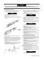
1. To disassemble the Housing (1 or 44), begin by unscrewing the
connection ring to remove the Power Cord (6 or 55).
2. Use a 29mm open end wrench to unscrew the coupling (56 or 6).
NOTICE
This is a left-hand thread.
3. Using a #1 phillips screwdriver, remove the Housing
Screws (2 or 45).
4. Separate the Housing by lifting the half with the three screw holes. If
necessary, use a small screwdriver to pry the Housing apart. Refer to
Dwg. TPD1816.
(Dwg. TPD1816)
5. Remove the Trigger (17 or 51), Trigger Spring (18 or 52) and the
Trigger Pin (19 or 53).
6. Remove the Housing Bushing (7 or 54) from the back of the tool.
Disassembly of the Clutch Housing & Gear Case
1. Lift the Clutch Housing (53 or 8), Gear Case (37 or 22) and Motor
Assembly from the Housing. While holding firmly, pull the Gear Case
away.
2. Tap the end of the Gear Case on the work bench to remove the
Motor Clamp Spacer (36 or 23) and the Gear Head
Assembly (38 or 20).
3. Remove the Gear Head Planet Gears (39 or 21) from the Gear Head.
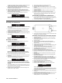
4. Remove the Push Rod (46 or 17) from the Gear Case. Fit the two
notches at the rear end of the Gear Case Fixture part
no. EL0410B-J37. Refer to Dwg. TPD1813.
(Dwg. TPD1813)
5. Using a slotted screwdriver, remove the Front Bit Retainer Retaining
Ring (60 or 3) from the Bit Holder Assembly (48 to 12).
6. Remove the Bit Retainer Sleeve (58 or 4) and Bit Retainer Sleeve
Spring (59 or 5).
7. Remove the two Bit Retaining Balls (50) from the Bit Holder by
tapping the Bit Holder on the work bench.
NOTICE
Model EL0109 has only one Bit Retaining Ball (11).
8. Unscrew and remove the Clutch Adjusting Ring (57 or 1) from the
Clutch Housing. For Model EL0109, also remove the Bit Retainer
Spring (2).
9. Remove the three Clutch Adjusting Pins (54 or 7) from the Clutch
Housing and the Bit Retainer Sleeve Spring.
10. Remove the Bit Retainer Retaining Ring (55) using external snap ring
pliers.
11. Using a 21mm open end wrench on the flats of the Clutch Housing
Assembly, unscrew and remove the Clutch Housing.
NOTICE
This is a left-hand thread.
12. Remove the Clutch Spring Plate (52 or 9) and the Clutch
Spring (51 or 10).
13. Lift the Bit Holder Assembly from the Gear Case.
For Model EL0109, remove the Cam Guide (13) and the two Cam
Guide Balls (14) from the Bit Holder.
For Models EL1007 and EL0410, remove the two cam Guide
Balls (49) and Cam Guide Sleeve (47) from the Bit Holder
Assembly (48).
14. Remove the Gear Case from the Gear Case Fixture. Turn it over and
push the Spindle Assembly (40 or 18) from the case.
15. Remove the Spindle Planet Gears (41 or 19) from the Spindle
Assembly.
16. For Model EL0109, remove the Cam (16) and Cam Guide Sleeve
Assembly (15) from the bearing.
For Model EL1007, remove the Cam Collar (45), the Cam (43), two
Camp Pins (44) and the Thrust Washer (42).
Cleaning and Inspection of the Tool
1. Clean all mechanical parts you have disassembled in an approved
safety solvent in a well-ventilated area. Inspect for damage or wear.
2. For all Models, inspect the Bit Holder Assembly. If the bearing does
not rotate smoothly, replace the Bit Holder Assembly.
3. Inspect the Cam. If it is worn, replace it.
4. For Model EL1007, inspect the Cam Pins (44). If they are worn,
replace them.
5. For Model EL0109, inspect the Cam Guide Sleeve. If the bearing of
the Cam guide Sleeve does not rotate smoothly, replace it.
6. Inspect all the Gear head Planet Gears. If the teeth are worn or
damaged, replace them.
7. Inspect the Gear Case. If the inner gear teeth are worn or damaged,
replace them.
8. Inspect the Spindle Assembly. If the bearing does not rotate
smoothly, replace the Spindle Assembly.
Disassembly and Inspection of the motor
1. Remove the Motor Assembly, the Plunger (13 or 37) and the Plunger
Spring (14 or 38) from the Housing.
2. Using a thin slotted screwdriver, release the tension on the Brush
Spring (25 or 35) and remove the two Brush Assemblies (24 or (33)
from the Rear End Plate (23 or 32).
3. Carefully pull the copper wires to remove the Brush Assemblies from
the Rear End Plate.
NOTICE
Be careful not to damage the wires.

Form 16575318-Edition 1 3
If the Brush Assemblies need to be replaced, desolder the blue and
red Motor wires and remove the Brush Screws (26 or 34).
4. Using a thin blade screwdriver, remove the Motor Assembly
Springs (34 or 31) by inserting the screwdriver between the Springs
and Rear End Plate and prying upward.
5. Remove the Font End Plate (33 or 24) from the Field (32 or 25).
6. Remove the Rear End Plate and the Motor Plate (27 or 30) by
inserting a slotted screwdriver into the space between the Rear End
Plate and the Field and prying upward.
7. While pushing the Rear Armature Bearing (28 or 29), pull the
Armature (31 or 26) from the Field.
NOTICE
Do not damage the commutator or windings on the Armature.
Hold the Armature body, not the commutator, when removing.
8. Remove the Push Rod (35 or 36) from the Armature.
9. Inspect the Push Rod. If it is worn, replace it.
10. Inspect the Rear Armature Bearing. If it does not rotate smoothly,
replace it.
11. Inspect the gear teeth on the Armature. If they are worn or damaged,
replace the Armature.
12. Inspect the front armature Bearing. If it does not rotate smoothly,
replace the Armature.
13. Inspect the commutator. If it is worn, replace the Armature.
14. Clean the Armature. Field, Motor Plate and the End Plates using a
piece of fine cloth. For excess contamination, spray with contact
cleaner and brush if necessary.
Disassembly and Inspection of Electronics
1. To remove the Trigger Switch (8 or 50), Reverse Switch (9 or 48) or
Brake Switch (15 or 42), remove any screws and pull the Switch from
the Housing. Desolder and remove the lead wires.
2. To remove the Insulator (71 or 49), desolder the lead wires.
Assembly
Assembly of the Electronics
NOTICE
Before soldering any wire, slip a piece of heat shrinkable tubing
over the wire.
1. To assemble the Electronic Components, resolder all wires to the
Insulator (71 or 49). Also resolder all wires to the Brake Switch
(15 or 42) and the Trigger Switch (8 or 50).
2. Reattach the Brake Switch to the Switch Plate (10 or 39) and screw
the Plate into the Housing (1 or 44).
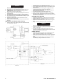
3. Insert all electronic components into their proper locations. Refer to
Dwg. TPD1817.
NOTICE
Be sure the notch in the Insulator fits with the tab in the
Housing.
Assembly of the Motor
1. Carefully insert the gear end of the Armature (31 or 26) into the
notched side of the Field (32 or 25).
NOTICE
Be careful not to damage the commutator or windings.
2. Install the Front End Plate (33 or 24) onto the Field.
3. Place the Motor Plate (27 or 30) onto the Rear End Plate (23 or 32).
NOTICE
Be sure to install the Motor Plate correctly. The edge of the
Motor Plate must be parallel to the step in the Rear End Plate.
4. Push the Rear End Plate into the notches of the Field.
5. Snap the motor Assembly Springs (34 or 31) into the notches of the
End Plates.
6. Insert the Brush Assembly (24 or 33) into the Rear End Plate. Be
careful not to twist or damage the copper wire.
NOTICE
Make sure the Brush Assembly is positioned correctly. The
connection point of the copper wire on the Brush Assembly
should be closer to the rear end than the front end of the Motor
Assembly.
7. Insert the Brush Spring (25 or 35) into the Rear End Plate. Using a
small screwdriver to tension the Spring, insert the end of the Brush
Spring into the notch on the End Plate.
8. Solder the blue nd red Motor lead wires if the Brush Springs were
replaced. Refer to Dwg. TPD1814.
(Dwg. TPD1814)
9. Apply grease to both ends of the Push rod (35 or 36) and insert it into
the center hole of the Motor Assembly.
Assembly of the Gear Case and Clutch Housing
1. Place the three Spindle Planet Gears (41 or 19) onto the Spindle
Assembly (40 or 18).
2. Place the three Gear Head Planet Gears (39 or 21) onto the Gear
Head Assembly (38 or 20).
3. Grease the gears.
4. Place the Gear Head Assembly onto the Spindle Assembly.
5. Grease both sides of the Thrust Washer (42) and place it on the
Spindle bearing.
6. Insert the Cam (43 or 16) into the Spindle Assembly.
7. While rotating the Gear Case (37 or 22) and holding the Cam, insert
all parts into the Gear Case.
8. Grease the Gear Case side of the Motor Clamp Spacer (36 or 23)
and insert the Motor Clamp Spacer into the Gear Case.
9. For Model EL1007, grease the notches on the Cam and place the
two Cam Pins (44) into the notches.
10. Grease the inside of the bit Holder Assembly (48 or 12).
11. Insert the Cam Guide Sleeve (47 or 15) into the bit Holder.
12. Grease the ball bearings under the spring support on the Bit Holder
Assembly.
13. Grease the holes on the bit Holder and insert the two Cam Guide
Balls (49 or 14).
14. For Model EL1007, grease the inside of the Cam Collar (45) and
place it onto the Bit Holder.
15. For Model EL0109, grease the bottom end of the Bit Holder
Assembly and place the Cam Guide (13) onto the Bit Holder. Grease
the holes in the Cam Guide and insert the two Cam Guide Balls.
16. Fit the two notches at the rear of the Gear Case Assembly into the
Gear Case Fixture part no. EL0410B-J37.
17. Place the Bit Holder Assembly into the Gear Case.
18. Place the Clutch Spring (51 or 10) and the Clutch Spring
Plate (52 or 9) over the Bit holder.
19. Place the Clutch Housing (53 or 8) partially into the Gear Case.
NOTICE
This is a left hand thread.
At the middle of the Clutch housing threads apply Loctite ®* Thread
Locker 3 Bond 1406 to three of the threads. Screw the Clutch Hous-
ing all the way into the Gear Case.
20. Using an open end torque wrench, tighten the Clutch Housing to 20
Nm torque.
21. Install the Bit Retainer Retaining Ring (55 or 3) into the groove of the
bit Holder. Place the side with the sharp edge first.
22. Apply grease to the holes of the Bit Holder and insert the two Bit
Retaining Balls (50 or 11) into the Bit Holder.

4 Form 16575318-Edition 1
NOTICE
Model EL0109 has only one bit Retaining Ball.
23. Apply grease to one end of the each Clutch Adjusting Pin (54 or 7)
and insert them into the Clutch Housing.
24. For Model EL0109, place the Clutch Adjusting Ring (1) and Bit
Retainer Spring (2) onto the Clutch Housing.
25. Grease the inside lip of the Clutch Adjusting Ring and thread it onto
the Clutch Housing.
26. Install the Bit Retainer Sleeve Spring (59 or 5). Grease the inside of
the bit Retainer Sleeve (58 or 4) and place it onto the Bit Holder.
27. Using a slotted screwdriver, install the Bit Retainer Retaining ring into
the groove of the Bit Holder.
28. Unclamp the Assembly Fixture from the vise and turn it over to
remove the Clutch and Gear Case.
29. Grease both ends of the Push Rod (46 and 17) and insert it into the
Gear Case.
Adjustment of the Brake Switch Timing
1. If the Brake Switch needs adjusting, loosen the Switch Plate Screws
(11 or 40). See Dwg. TPD1815.
(Dwg. TPD1815)
2. Apply grease to the end of the Plunger (13 or 37) and insert it with
the Plunger Spring (14 or 38) into the Switch Plate.
3. Insert a Switch Adjusting Gauge Rod part no. EL0410B-SG into the
Motor Assembly.
4. Place the Gear Case and Motor together by aligning the Motor
Assembly Springs with the notches in the Gear Case.
5. Place the Assembly into the Housing by aligning the hole in the
Motor with the tab in the Housing.
6. Push the Brake Switch forward until the Switch clicks.
7. Tighten the Switch Plate Screws at this position to 1.6 KG-cm.
8. Remove the Switch Adjusting Gauge Rod. Grease and install the
Push Rod (35 or 36) into the Motor Assembly and refit the hole in the
Motor to the tab in the Housing.
Assembly of the Housing
1. Install the Housing Bushing (7 or 54) in the groove of the Housing.
2. Install the Trigger (17 or 51) with the Trigger Pin (19 or 53) and
Spring (18 or 52) into the Housing.
3. Install the second half of the Housing, while holding the Trigger in
place.
4. Tighten the Housing Screws (2 or 45) to 1-1/2 inch pounds.
NOTICE
Do not overtighten the Housing Screws.
5. Install the Coupling (56 or 6) with an open end torque wrench and
tighten to 7 Nm torque.
6. For repair and trouble shooting of the Controller, refer to the
Operations and Maintenance Manual for Model EC24E and EC24U
Screwdriver Controllers, Form No. P7215.
Testing the Tool
1. Test forward and reverse operation of the tool by depressing the
Trigger with the Reverse Switch (9 or 48) in each position.
2. Tighten the Clutch Adjusting Ring all the way, loosen it one turn and
test for proper shut-off and maximum torque using an appropriate
tester.
3. Reset the Clutch Adjusting Ring to mid-scale and check torque
repeatability by cycling the tool between 5-10 times.
(Dwg. TPD1817)

Form 16575318-Edition 1 5
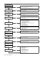
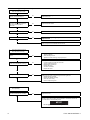
Troubleshooting Guide
1. Screwdriver fails to rotate
(forward or reverse)
Is there power to the tool?
Yes
1. Defective Power Cord Assembly.
Replace the Power Cord Assembly if necessary.
2. No power from the controller.
Repair or replace (see Controller Service manual).
No
Does the Trigger Switch click
when the Trigger is depressed?
Defective Trigger Switch.
Replace the Trigger Switch.
No
Can the bit be turned by hand
when the tool is unplugged?
1. Planetary gearing defective.
Replace the Planet Gears, Spindle Assembly and Gear Head Assembly.
2. Clutch defective.
Repair or replace the clutch.
No
Yes
Does the tool operate properly
when bumped and jiggled?
1. Defective power cord.
Replace the Power Cord Assembly.
2. Forward/Reverse Switch defective.
Repair the Forward/Reverse Switch.
3. Defective solder connection.
Check all solder connections; resolder where necessary.
4. Defective Armature.
Replace the Motor Assembly.
5. Brush contact defective.
Replace the Brush Assembly.
No
Yes
Yes
Does brush wear appear
normal?
No
1. Worn or defective Brushes.
Replace the Brush Assemblies.
2. Defective Commutator.
Replace the Armature.
Yes
Does motor appear to be in
good condition?
No
Carbon buildup or dirt on Armature.
Clean the Armature using a good electrical contact cleaner and blow dry.
Yes
Does the Trigger Switch turn on
power to the Motor?
Trigger pad worn.
Replace the Trigger.
No
2. Screwdriver runs in one
direction but not the other.
Are wire leads in good condition
and properly soldered?
Yes
Defective solder connections.
Resolder and rewire if necessary.
No
Does Reverse Switch operate
properly?
Defective Reverse Switch. Replace it.
No
When gears are removed, will
the motor rotate?
No
Is planetary gearing smooth
when bit is rotated by hand?
1. Armature is in contact with the magnets.
Replace the motor.
2. Foreign material in the motor.
Clean the motor.
1. Bearing has failed.
Replace the Spindle Assembly.
2. Gears are worn or damaged.
Replace any defective gearing.
Clutch Assembly is worn.
Replace damaged or worn parts.
No
Yes
3. Bit does not rotate but
motor hums.
Yes
Yes

6 Form 16575318-Edition 1
Troubleshooting Guide (Continued)
Does the speed of the Bit exceed rated
speed by more than 100 rpm?
Yes
Motor magnet is demagnetized.
Replace the motor.
4. Shutoff brake malfunctions more
than one index of the Clutch.
No
Is Brake Switch functioning? (Does it
click when button is depressed and
does it test correctly with an
ohmmeter?
No
Defective Brake Switch.
Replace the Brake Switch.
Yes
Does Pushrod function properly?
No
Bent or worn Pushrod. Replace it.
Yes
Does Cam function properly?
No
Cam is worn and not providing adequate lift.
Replace the Cam.
Yes
Cam is worn and not providing adequate lift.
Replace the Cam.
Controller malfunctioning or defective.
Repair or replace. See Controller Service manual.
5. Tool makes abnormal sounds
when the motor is running.
No
Is there looseness at the assembly
points?
Yes
1. Screws are loose.
Tighten all Screws.
2. Clutch Housing is loose.
Tighten the Clutch Housing to the proper torque.
After removing the gear train does
motor sound normal when running?
No
1. Armature (31) is in contact with the Magnet.
Replace the motor
2. Foreign material has gotten into the motor.
Clean or replace the motor.
3. Ball Bearings are defective.
Replace the motor.
4. Armature is defective.
Replace the motor.
Yes
Is the gear train properly lubricate?
No
No grease on the gear train.
Apply a thin film of the recommended grease to the gear train.
1. Spindle Bearing has failed.
Replace the Spindle Assembly.
2. Gears are worn or dirty.
Clean or replace the gears.
6. Tool generates abnormal heat
when operating.
Yes
After removing the gear train, does tool
cool down and motor run normally?
No
Motor is defective.
Replace the motor.
Planetary gears and the Clutch require lubrication. Lubricate the Clutch and
gear train with the recommended grease.
NOTICE
Do not apply too much or too little grease.
Yes

Form 16575318-Edition 1 7
Related Documentation
For additional information refer to:
Electric Screwdrivers Product Safety Information Manual Form 16573685.
Electric Screwdrivers Product Information Manual Form 16578668.
Electric Screwdrivers Product Parts List Manual Form 16574642.
Manuals can be downloaded from www.irtools.com.

www.irtools.com
© 2005 Ingersoll-Rand Company
-
 1
1
-
 2
2
-
 3
3
-
 4
4
-
 5
5
-
 6
6
-
 7
7
-
 8
8


Ingersoll-Rand EL 24V Series Maintenance Information
- Type
- Maintenance Information
Ask a question and I''ll find the answer in the document
Finding information in a document is now easier with AI
Related papers
-
Ingersoll-Rand EL 24V DC Series Maintenance Information
-
-
-
-
-
-
-
-
-
Ingersoll-Rand QA1L High Torque Series Maintenance Information
Other documents
-
Hitachi DV 14DL2 User manual
-
-
 Yerf-Dog Spiderbox 2003 User manual
-
Polaris Trail Boss 330 2003 User manual
-
Arctic Cat 2015 XF 9000 High Country User manual
-
Chevrolet Corvette 1970 Repair & Tune-Up Manual
-
Briggs & Stratton Twin Cylinder L-Head User manual
-
-
-
DAELIM VJF125 User manual
