
GLT.MAN-145
Issue 1
Date: 12/4/2011 Page 1
TCP-IP Communicator
Instruction Manual

GLT.MAN-145
Issue 1
Date: 12/4/2011 Page 2
Contents
Introduction ............................................................................................................................................ 3
Connecting the unit to a Simplicity Panel ............................................................................................... 4
Preparing to configure the TCP-IP unit ................................................................................................... 5
Configuring the TCP-IP Communicator. .................................................................................................. 7
Connecting the TCP-IP Communicator to a network ............................................................................ 12
Configuring the Zeta Fire IP Alarm Panel software ............................................................................... 13
Running the Zeta Fire IP Alarm Panel Software .................................................................................... 17
Trouble shooting ................................................................................................................................... 20
Known issues running on Windows 7 ................................................................................................... 21

GLT.MAN-145
Issue 1
Date: 12/4/2011 Page 3
Introduction
The Zeta TCP-IP remote monitoring system has been designed to allow a simplicity panel to report all
system events to a remote PC. This includes alarms, pre-alarms, loop faults, general faults, panel
access (key on), menu access, changes to loop, changes to clock etc. In some instances, not all of this
information is desirable, so the system can filter for just the important information.
The Zeta TCP-IP remote monitoring system consists of 2 parts.
Firstly, there is the TCP-IP interface itself. This is a module that connects to the serial port of a
Simplicity fire alarm panel, and then connects into a LAN.
Secondly, there is a piece of software that is installed on the PC to which the TCP-IP interface will
forward event messages.
The system can essentially run in 2 ways.
LOCAL NETWORK REPORTING
If the PC to monitor the system is on the same network as the interface, the system can be
configured to report to the default network IP addresses of 192.168.xx.yy. Setting up this type of
system is very straightforward.
INTERNET REPORTING
The software is designed for monitoring several Simplicity panels, which may be spread over several
sites. Such a system is likely to be on several different “local networks”.
With this type of system, the unit is configured to report to the external IP address of the monitoring
PC, and it is likely that the routers on each network will need to be configured to allow access to the
required ports. (Consult your router manual for information on this)
The system uses ports 20000 and 10001, with further interfaces using ports 10002, 10003, 10004
etc.

GLT.MAN-145
Issue 1
Date: 12/4/2011 Page 4
Connecting the unit to a Simplicity Panel
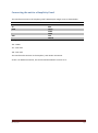
The Interface connects to the simplicity panel`s RS-232 port using 4 cores as shown below.
SIMPLICITY
IP-COMM
RX
TX2
TX
RX3
GND
GND5
-
DTR4
-
DSR6
DSR
12V
-
SHIELD
Configuration Jumpers
J10 – OPEN
J11 – Not used
J18 – Not used
The Interface also connects to the simplicity`s Aux Power connection.
As this is an RS232 connection, this wire should be limited to a metre or so.

GLT.MAN-145
Issue 1
Date: 12/4/2011 Page 5
Preparing to configure the TCP-IP unit
The TCP-IP communicator must be configured using the LANTRONIX configuration utility.
Firstly download and install this utility from the zeta alarm systems website.
The TCP-IP Communicator comes configured with a default IP Address of 192.168.1.100. In order to
configure the unit, it must be connected to a PC that can see this IP address (IE in the same subnet)
The options to connect are:-
1. If your network uses the 192.168.1.xxx subnet, then the TCP-IP communicator can just be
plugged into the network
2. If your network uses a different subnet, then you can either:-
a. Temporarily adjust the computer`s subnet to include the TCP-IP communicators
address (EG change subnet mask from 255.255.255.0 to 255.255.0.0)
b. Temporarily adjust the computer`s IP address to match the range of the TCP-IP
communicator. (This is probably best done on a laptop, or a PC that is not usually
connected to the network.) Then connect the PC to the TCP-IP UNIT EITHER with a
CROSSOVER NETWORK CABLE, or via a NETWORK SWITCH
To check the IP address of a PC, open a DOS window and type IPCONFIG. You will see something
like:-
Altering a computers TCP/IP settings will depend on which version of windows is being used, but it is
generally found by selecting the control panel, followed by network settings Finding the network
adapter icon, right clicking on it and selecting properties

GLT.MAN-145
Issue 1
Date: 12/4/2011 Page 6
.
Then click on internet Protocol 4, and then click properties button.

GLT.MAN-145
Issue 1
Date: 12/4/2011 Page 7
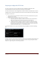
Configuring the TCP-IP Communicator.
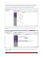
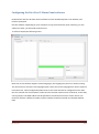
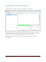
Open the Lantronix Device installer utility. After a few seconds, the program will display a screen
similar to below. The left hand panel shows the IP address of the PC. The right hand panel shows the
TCP-IP addresses of any units connected to the network. Click search to refresh the list.
Click on the XPort Icon for the TCP-IP unit, and its configuration information will be displayed

GLT.MAN-145
Issue 1
Date: 12/4/2011 Page 8
Click on the Web Configuration tab, then press the green GO arrow to display the unit`s
configuration web page. The unit will prompt for a User Name & password.
The default setting is blank, so press OK. If you decide to add a password, store it carefully to allow
future maintenance, and access to the unit.

GLT.MAN-145
Issue 1
Date: 12/4/2011 Page 9
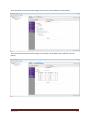
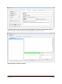
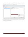
Click on the network menu. The network settings of the TCP-IP communicator can be set here. For a
local network, set the IP address and subnet mask. If the unit will communicate to a remote PC
across the internet, the gateway (Router) address and DNS server should also be added.
When finished, click OK, then click Apply Settings to save any changes. The following window is
shown.
If the unit`s IP address has been changed, you will need to repeat the instructions to return to the
devices web page.

GLT.MAN-145
Issue 1
Date: 12/4/2011 Page 10
There should be no need to make changes on the server menu (default is shown below)
There should be no need to make changes on the Serial Tunnel/Hotlist menu (default is shown
below)

GLT.MAN-145
Issue 1
Date: 12/4/2011 Page 11
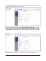
On the Channel 1/Serial Settings page, check that the port setting is set to RS232, 9600,8,n,1, with
no flow control. Click OK & Apply settings if necessary.
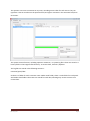
On the Channel 1/Connection page, check that ACTIVE CONNECT is set to Autostart. Enter the IP
address of the receiving PC, and check that the local port and remote port are correct. Local port =
10001,10002,10003, etc incrementing by 1 for each successiveTCP-IP communicator unit connected
to the system, and the remote port will be 20000. Click OK & Apply settings if any changes have been
made.
The Email Trigger and configurable pins sections are not used on the TCP-IP communicator.

GLT.MAN-145
Issue 1
Date: 12/4/2011 Page 12
Connecting the TCP-IP Communicator to a network
If the communicator was configured on a stand-alone PC, it can now be connected to the building`s
network. At the PC that will monitor events, run the lantronix software. If the software sees the unit
and reports it as online, then the connection is working.
The connection can be double checked with the ping command to the units IP address
The network link has now been established and the main monitoring software can be installed and
configured.
Remember: If you have altered the IP address, or subnet mask of your PC, in order to program the
TCP-IP interface, you should set it back to the previous value.

GLT.MAN-145
Issue 1
Date: 12/4/2011 Page 13
Configuring the Zeta Fire IP Alarm Panel software
Download the Zeta Fire IP Alarm Panel software from the ZetaAlarmSystems.com website, and
install as prompted.
Run the software. Depending on your computer set-up, the firewall may show a warning. For this
software to work, you will need to allow access.
It will then display the following screen.
Note that as this software supports several languages, the language may be set to another setting.
The second menu, last item is the language option. Select the correct language from here if required.
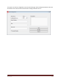
From the menu, select Configuration/New Central. The screen will ask for configuration info. Note
that if a customer has several panels, make sure the customer name on each is identical, so that they
can be grouped. The MAC address will be printed on the network connector of each TCP-IP unit.
Each unit will have a different number, and this number should be entered into the MAC address
field.

GLT.MAN-145
Issue 1
Date: 12/4/2011 Page 14
The software allows 4 sets of contact details to be logged for each panel. The comments section is
useful for noting site information which may be useful in the event of an alarm.
Add extra Simplicity panels as required.

GLT.MAN-145
Issue 1
Date: 12/4/2011 Page 15
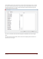
As the Simplicity reports various system events as well as alarms & faults (Eg key access, or setting
the clock), the software provides a filter to choose which events will be reported as alarm events.
From the list below, press >> to move an event to the alarm list. Select all events that you want
reported as alarms, then press Accept.
Any events not selected as alarms will still be displayed on the HISTORY tab, but will not flag an
alarm.
The system should now be connected. Create an event on the simplicity panel to check that it is
reported at the monitoring PC.

GLT.MAN-145
Issue 1
Date: 12/4/2011 Page 16
The System can also be configured to send an email message. Select Configuration/Email, and enter
the details of the email account that the alarm message should be sent to.

GLT.MAN-145
Issue 1
Date: 12/4/2011 Page 17
Running the Zeta Fire IP Alarm Panel Software
The Quiescent state of the Zeta Fire IP Alarm Panel software is shown below.
The panel name turns green to show that the system is on line, or red if it is off line. (But if only one
panel is configured, it will be permanently highlighted, so the colour is not visible)
When there are no current alarms, the system status indicator is a green bar, to show that
everything is OK.

GLT.MAN-145
Issue 1
Date: 12/4/2011 Page 18
If there is an event, this status indicator turns red to show that something has happened. The panel
(or panels) that have signalled an event will be listed in the window below the system status
indicator bar. It is displayed as “Company”/”Panel”/MAC address
After the operator has taken the relevant action (Such as check with building security, contact the
maintenance company etc) he can select the panel and click free alarm. This returns the status back
to normal when all events are cleared.

GLT.MAN-145
Issue 1
Date: 12/4/2011 Page 19
The operator can insert a comment at any time, recording action taken for each event. They can
type their name or ID code into the operator field, and type a comment in the comment field, then
click insert.
The system stores all events, including operator comments, in system log files. These are stored in a
history folder in the Program files directory. To access them, click File / Explorer.
The log files are stored in the following structure:-
Customer/panel/date
So there is a folder for each customer name. Within each folder, there is a sub folder for each panel.
And within these folders the events are stored for each date, allowing easy access to events on a
certain date.

GLT.MAN-145
Issue 1
Date: 12/4/2011 Page 20
Trouble shooting
Configuration settings
Recheck that the following settings have been made in the Lantronix configuration software and
saved:-
The IP address of the Communicator
The Destination IP address of the host PC
The communication port settings (20000 and 10001)
That the serial port is set to 9600,8,n,1,no flow control
That the Active connect setting has been set to autostart
Port settings
The TCP IP communicator has been designed to be as straightforward as possible to configure.
However due to the nature of it`s operation, the software will usually be blocked by default by most
firewalls & routers.
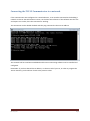
To check if the software can communicate, open a command line window & type netstat. This will
bring up a list of all network connections. Look for a listing that shows a connection between port
20000 on your PCs IP address and port 10001 on the IP communicators IP address
If the connection is not established then it is likely that something is blocking the port.
LAN Operation
Open your firewall program and look for ”IP Logging software for Zeta Alarm Systems“. Check that
this program is allowed access.
Internet Operation
Firstly check the firewall settings. If these are OK, then it is likely the Router is blocking the port. Log
on to the router and adjust the NAT settings to allow port 20000 and 10001. (Consult your network
administrator if you need advice on doing this)
Page is loading ...
-
 1
1
-
 2
2
-
 3
3
-
 4
4
-
 5
5
-
 6
6
-
 7
7
-
 8
8
-
 9
9
-
 10
10
-
 11
11
-
 12
12
-
 13
13
-
 14
14
-
 15
15
-
 16
16
-
 17
17
-
 18
18
-
 19
19
-
 20
20
-
 21
21


Ask a question and I''ll find the answer in the document
Finding information in a document is now easier with AI
Related papers
Other documents
-
 ZiFiSense APZT-GO01 Operating instructions
-
ZiFiSense Zeta Low Power Wide Area Network 4-20mA Transceiver Operating instructions
-
 ZETA Music Systems Pro Violin User manual
-
Diamond Systems Zeta Miniature User manual
-
ZiFiSense ZETA Low-Power Wide Area Networks Owner's manual
-
ZiFiSense D485ZT User manual
-
 ZETA Music Systems PB-304 User manual
-
 ZETA Music Systems XB-306 User manual
-
 ZETA Music Systems Strados Violin User manual
-
Lantronix EDS8PR User manual


