Page is loading ...


WIRELESS SUPERVISED PIR
MOTION DETECTOR
With PET IMMUNITY up to 27Kg
INSTALLATION INSTRUCTIONS
P/N 7101504 REV. A A.Y.
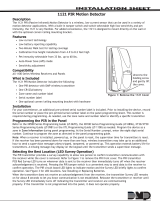
PRODUCT DESCRIPTION 3
The DFW is a battery powered passive infrared
motion detector with a built-in transmitter.
This transmitter can be used in a variety of motion
detection applications. When the passive infrared
sensor detects motion in its field of view, the
transmitter sends a wireless signal to the re-
ceiver.
The DFW sends three different signals: “Alarm”,
“Low Battery” and “Tamper”.
In a typical installation, the motion detector is wall
mounted indoors.
The sensor will monitor the infrared level in its
detection pattern. If the level increases or de-
creases rapidly (as when a person moves through
the area) the transmitter triggers, sending an
alarm signal to the receiver.
The unit is powered from a 3 volt lithium battery.
The life of the battery depends upon the activity in
the area where the detector is installed. When the
battery is low, a low battery signal will be sent to
the receiver.
If the detector cover is removed, the tamper switch
triggers the transmitter to send an alarm.
The DFW has a unique Automatic Power Saver
(APS) circuit designed to conserve battery life.
This APS circuit rearms the transmitter 2 minutes
after the last movement has been detected.
FEATURES DETECTION PATTERN TYPICAL INSTALLATION
Low current ASIC PIR technology
Powered by a 3 volt lithium battery
Built in Automatic Power Saver (APS)
Low battery report
Tamper report
Walk test mode 1 for PIR coverage
Walk test mode 2 for RF signal
Pet immune up to 27Kg
Adjustable Mounting Bracket
2 Transmission modes, power save (normal)
and Frequent (test)
Select the mounting location so that an intruder
will cross the beams of the selected pattern.
Since the detector is a wireless transmitter, do not
install it in areas where large metal objects could
interfere with the transmission of signals.
Avoid mounting the detector as follows:
Facing a door with a wireless door/window
transmitter.
Facing direct sunlight.
Facing areas that may change temperature
rapidly.
Facing an air duct or areas with substantial
airflows.
On or near metal surfaces.
The DFW performs best when provided with a
constant and stable environment.
REMOVAL OF FRONT COVER MOUNTING DETECTOR BASE
1. To remove the front cover, unscrew the holding
screw and gently raise the front cover.
2. To remove the PCB, carefully unscrew the
holding screw located on the PCB.
3. Knock out the desired holes for installation.
4. Mount the detector base to the wall, corner.
5. Reinstall the PCB by fully tightening the hold-
ing screw.
6. Install the battery in the battery holder observ-
ing the polarity.
7. Replace the cover by inserting it back in the
appropriate closing pins and screw in the
holding screw.
SETTING-UP THE DETECTOR LAYOUT
Setting the Sensitivity Adjustment
PIR Adjust Potentiometer
Use this potentiometer to adjust the detection
sensitivity between 68% and 100% (factory set
to 84%). Rotate the potentiometer clockwise to
increase sensitivity. Rotate the potentiometer
counter-clockwise to decrease sensitivity.
Pulse Width Switch
The sensitivity adjustment switch sets up the
detector for normal or harsh environment condi-
tions.
Position 1= Normal
Position AUTO = Harsh
The “1” position setting is for normal operation.
The “AUTO” position setting is for harsh environ-
ment locations with air drafts.
SETTING THE PET IMMUNITY SWITCH
33LB = 15KG PET IMMUNITY
60LB = 27KG PET IMMUNITY
Setting Transmission Mode
The transmission mode is changed by moving
the jumper pins on the TRANS board, from one
option to the other.
Normal:
When the IR motion is detected, an RF trans-
mission will be sent, then the DFW will save
power and not transmit for another 2 minutes.
Test:
In this mode every time IR motion is detected,
an RF transmission will be sent. This mode will
not time out, making it ideal for a door minder
situation.
1 AUTO
PULSE
15Kg 27Kg
PET
PI R
SENSITI VITY
ADJUSTMENT
DETECTI ON
LED
TRANSMISSION
LED
TRANSMISSION
MODE
NORMAL TEST
TAMPER
SWI TCH
TEST
BUTTON
Available in TRX 918Mhz
TRX PIR

WALK TEST ALARM TRANSMISSION TEST WALL INSTALLATION
TEST PUSHBUTTON
The Test Pushbutton is located below the
Tamper switch.
This button is used to activate Walk test mode 1
and 2.
WALK TEST MODE 1 (PIR COVERAGE)
Press the Test Pushbutton for a short time (less
than 1 second). This activates the LED to trigger
with IR detection only, without an RF transmis-
sion, for 1 minute. Allowing you to walk around
and check the PIR coverage area & sensitivity.
WALK TEST MODE 2 (RF SIGNAL)
Pressing the Test Pushbutton for at least 4
seconds, (until the LED flashes 4 times) will
activate both the LED and an RF transmission
with IR detection, for 1 minute.
Note. The PIR TRANS Jumper must be set to Normal
mode, no RF transmission will be sent if set to Test
mode
BATTERY TYPE BATTERY INSTALLATION
A 3-volt lithium battery powers the unit.
The battery provides about 3 years of continuous
operation (depending on the amount of activity).
If the battery reaches a factory preset low level, a
LOW BATTERY signal will be sent. From this
moment, the detector remains operational for
another 30 days giving enough time to replace
the battery.
The battery must be replaced
by a 3 volt lithium battery
Models: DL123A DURACELL INC.
CR123A SANYO
ELC.CR123A GP
Or an equivalent.
1. Remove the front cover.
2. Take out the old battery.
3. Be sure to insert the battery correctly with
the PLUS terminal of the battery to the
right-hand side.
Compatible Receivers:
TECHNICAL SPECIFICATION WARRANTY
Event Transmission Alarm, Test, Low Battery
Transmission Protocol Freelink Supervised
Detection Method Quad Element PIR (ASIC Based)
Detection Speed 1 ~ 5 ft/sec. (0.3 ~ 1.5 m/sec)
Lens Type Spherical Hard Lens
Detection Coverage 90° 50 ft x 50 ft (15m x 15m)
Environment Condition Switch for Normal or Harsh selection
Battery Lithium. 3V Type: xx123 Size: 2/3AA
Current Consumption Standby: 8-10 mA Transmission: TBD
Power Saving APS (Automatic Power Saver)
Installer Test Modes LED Indicator (RF & Optic)
Walk test & Alarm transmission test
Operation Temperature Range -10°C to +60°C
Dimensions 4.8” x 2.5” x 1.45” (122mm x 63mm x 37mm)
Weight (inc. battery) 3.88Oz (110 gr)
Enabling & Assigning Radio Zones
Enabling & Assigning radio zones are both setup under address P122E.
P 122 E (1-16) E (Turn On Options 1 & 5)
Zone 1 to 16 that you wish to Change
Radio Detector Type
The DFW transmits in the Freelink protocol, you have the option to select: Supervised(3) or Un-
Supervised(4) default. under address P127E.
* I n Supervised mode every 15 minutes the detector will communicate with the panel, confirming it
is still operating and the battery is good.
P 127 E (1-16) E 3 E
Zone 1 to 16 that you wish to Change
Learning Radio Device
Insert the 3volt battery into the DFW, then Hold Down the Tamper Switch.
Now go to address P164E and choose a zone slot 1-16 and Enter
Zone slot 1 to 16 that you wish to learn in to.
P 164 E (1-16) E= the keypad should start beeping.
Now Release the Tamper Switch, the TX LED should come On.
= the keypad should stop beeping.
( For other control panels please follow the manufactures installation manual)
CEILING INSTALLATION
TRX Tranceiver
Transmission Frequency 918Mhz
The DFW will work on: ESL-2, Crow Runner
RX-DEC/FW with a compatible Receiver.
PROGRAMMING DFW INTO AN ESL-2 or Crow Runner CONTROL PANEL COMPATIBLE RECEIVERS / DEVICES
/