V
ACUUM METER
Model : VC-9200
Your purchase of this VACUUM METER marks a step forward for
you into the field of precision measurement. Although this
METER is a complex and delicate instrument, its durable structure
developed. Please read the following instructions carefully and
always keep this manual within easy reach.
OPERATION MANUAL

TABLE OF CONTENTS
1. FEATURES................................................................1
2. TYPICAL APPLICATION............................................. 2
3. SPECIFICATIONS......................................................2
3-1 General Specifications......................................... 2
3-2 Electrical Specifications.......................................
.
3
4. FRONT PANEL DESCRIPTION....................................
.
4
4-1 Display...............................................................4
4-2 Power Button.....................................................
.
4
4-3 Data Hold Button................................................ 4
4-4 " Max./Min. " Button...........................................
.
4
4-5 Unit Button........................................................
.
4
4-6 Battery Compartment/Cover................................ 4
4-7 Sensor Input Socket...........................................
.
4
4-8 RS-232 Output Terminal.....................................
.
4
4-9 Port Connector ( 1/4" NPT )............................. 4
4-10 Vacuum Sensor Main body.............................. 4
4-11 Plug of Vacuum Sensor..................................... 4
4-12 Adapter connector that convert 1/4" NPT
to 1/4" PS......................................................... 4
4-13 Port Connector ( 1/4" PS ).................................4
5. MEASURING PROCEDURE.........................................
.
5
6. AUTO POWER DISABLE.............................................7
7. RS232 PC SERIAL INTERFACE................................... 7
8. BATTERY REPLACEMENT..........................................
.
9
9. OTHER OPTIONAL ACCESSORIES..............................9

1
.
FEATURES
* Absolute vacuum & absolute pressure measurement.
* Wide measure range from 1 to 1500 mbar.
* Overload protection up to 2000 mbar max.
* Separate probe, easy operation.
* Application : Automobile, Industrial, laboratory,
heating, ventilation, medical hospital.....
* Heavy duty sensor used for air, oil gas, liquid.
* 8 kind display units ( torr, mm Hg, micron, mbar,
KPa, Pa, inch Hg, psi ) select by push button on the
front panel.
* Auto shut off saves battery life.
* Microprocessor circuit assures maximum possible
accuracy, provides special functions and features,
* Records maximum & minimum readings with recall.
* Data Hold function for stored the desired value on
display.
* Built-in low battery indicator.
* RS232 PC serial interface, can match the personal
computer used as the Data Logger, Recorder....
1

2. TYPICAL APPLICATION
* Measure pneumatic pressures.
* Measure automobile engine pressures.
* Pressure for super heat measurements.
* Hydraulic servo controls.
* Refrigeration.
* Air conditioning.
* Food processing.
3. SPECIFICATIONS
3-1 General Specifications
Display 61 mm x 34 mm supper lar
g
e LCD
display. 15 mm ( 0.6" ) di
g
it size.
Display units 8 kind display units : torr, mm H
g
,
micron, mbar, KPa, Pa, inch H
g
, psi.
Circuit Microprocessor LSI circuit.
Function Data hold, memory ( max., min.)
Sensor * Separate probe, easy operation.
probe * Heavy duty sensor used for
vacuum measurement of air, oil
g
as,
liquid.
Data hold By push button.
Data record Record maximum & minimum
readin
g
s.
Data output RS 232 PC serial interface.
Samplin
g
time Approx. 0.8 second.
Power off Auto shut off, saves battery life, or
manual off by push button.
Operatin
g
0 to 50 ( 32 to 122 ).℃℉
temperature
Operatin
g
Less than 80% R.H.
humidity
2

Power supply 006P DC 9V battery(heavy duty).
Power current Approx. DC 7.1 mA.
V
acuu
m
1/4" NPT or 1/4" P
S
senso
r
*
Included one adapter connector that convert
port Connecto
r
the 1/4" NPT to 1/4 " PS.
Wei
g
ht Instrument :
220
g
/0.48 LB.
Sensor probe :
183
g
/0.4 LB.
Dimension Meter :
180 x 78 x 34 mm
( 7.1 x 3.1 x 1.4 inch )
Sensor probe :
102 mm x 30 mm Dia.
( 4.02 inch x 1.2 inch Dia. )
Accessories * Vacuum sensor probe..............
.
1 PC.
* Instruction manual................... 1 PC.
included * Hard carryin
g
case................... 1 PC.
Optional * Data acquisition software
accessories ( Windows version ),
SW-U801-WIN.
* RS232 cable, UPCB-01
* Data lo
gg
er, DL-9601A.
* SD Data lo
gg
er, DL-9602SD.
3-2 Electrical Specifications
Unit Max. ran
g
e Resolution Accuracy
mbar 1500 mbar 1 mbar
KPa 150.0 KPa 0.1 KPa ± 1 % F. S.
Pa 150,000 Pa 100 Pa ( 23± 5 )℃
torr 1125 torr 1 torr
Note :
mm Hg 1125 mm Hg 1 mm Hg
Included linearity,
micron 1125,000 micron 1000 micron
hysteresis and
inch Hg 44.30 inch Hg 0.02 inch Hg
repeatability
psi 21.75 psi 0.01 psi F.S.: Full Scale
3

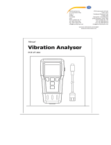
4. FRONT PANEL DESCRIPTION
Fig. 1
4-1 Display 4-8 RS-232 Output Terminal
4-2 Power Button 4-9 Port Connector ( 1/4" NPT )
4-3 Data Hold Button 4-10 Vacuum Sensor Main body
4-4 " Max./Min. " Button 4-11 Plug of Vacuum Sensor
4-5 Unit Button 4-12 Adapter connector that
4-6 Battery Compartment/ convert 1/4" NPT to 1/4" PS
Cover 4-13 Port Connector ( 1/4" PS )
4-7 Sensor Input Socket
4

5. MEASURING PROCEDURE
1)Plug the " Plug of Vacuum Sensor " ( 4-11, Fig. 1 ) into
meter's " Sensor Input Socket " ( 4-7, Fig. 1 ).
2)Power on the meter by pressing the " Power Button " ( 4-2,
Fig. 1 ).
3)To select different measuring unit by pressing the " Unit
Button " ( 4-5, Fig. 1 ). There are eight units for your choice.
4)Connect the " Port Connector of Vacuum Sensor " ( 4-9,
or 4-13, Fig. 1 ) to the equipment that intend to be
measured the vacuum value.
5)Apply the equipment and the vacuum meter will show the
vacuum value.
6)Data Hold
During the measurement, pushing the " Data Hold
Button " ( 4-3, Fig. 1 ) will freeze the measured value on
display and there will indicate a " HOLD " symbol.
* Push the "Data Hold Button" again to exit the
data hold function.
7)Data Record ( Maximum, Minimum reading )
* The DATA RECORD function displays the maximum
and minimum readings. To start the DATA RECORD
function, press the " Max./Min. Button " ( 4-4, Fig. 1 )
once. " REC " symbol will appear on the LCD display.
* With the " REC " symbol on the display :
a)Push the " Max./Min. Button " ( 4-4, Fi
g
. 1 )
once, the " Max " symbol alon
g
with the maximum
value will appear on the display.
b)Push the " Max./Min. Button " a
g
ain, the " Min "
symbol alon
g
with the minimum value will appear
on the display.
c) To exit the memory record function, push the
" Max./Min. " button continuously for around
2 seconds. The display will revert back to the
current readin
g
.
5

8 ) For quick measurement, follow the procedures
shown below :
Main procedures :
Connect the " Sensor Plug " to the meter's " Input Socket ".
Power on the meter & select the display unit.
Connect the pressure sensor connector with the equipment.
Apply the equipment and
g
et the pressure value.
Optional measuring procedures :
DATA HOLD MEMORY RECORD RS232 OUTPUT
Max., Min.
Power management :
AUTO POWER OFF or MANUAL POWER OFF
(Not available durin
g
Memory Record function)
9) Measuring considerations :
* The sensor diaphragm can be damaged by solid or
sharp objects. Never insert any object into the inlet port.
* The vacuum sensor is compatible with industrial gases
& liquid that are compatible with ceramic material. To
determine the compatibility of a liquid or gas, refer to
manufacture's specification.
6

6. AUTO POWER OFF DISABLE
The instrument has built-in " Auto Power Off " in
order to prolong battery life. The meter will switch off
automatically if no buttons are pressed for around 10
minutes.
To inactivate this feature by pressing the " Max./Min. "
button ( 4-4, fig. 1 ) to get into the memory record
function during the measurement.
7. RS232 PC SERIAL INTERFACE
The instrument features an RS232 output via 3.5 mm
Terminal ( 4-8, Fig. 1 ).
The connector output is a 16 digit data stream which
can be utilized to the user's specific application.
An RS232 lead with the following connection will
be required to link the instrument with the PC
serial input.
Meter PC
(3.5 mm jack plug) (9W 'D" Connector)
Center Pin..................................
.
Pin 2
Ground/shield................................Pin 5
7

The 16 digit data stream will be displayed in the
following format :
D15 D14 D13 D12 D11 D10 D9 D8 D7 D6 D5 D4 D3 D2 D1 D0
Each digit indicate the following status :
D0 End Word
D1 & D8 Display readin
g
, D1 = LSD, D8 = MSD
For example :
If the display readin
g
is 1234, then D8 to D1 is
:
0000123
4
D9 Decimal Point(DP), position from ri
g
ht to the left
0 = No DP, 1= 1 DP, 2 = 2 DP, 3 = 3 DP
D10 Polarity
0 = Positive 1 = Ne
g
ative
D11 & D12 Annunciator for Display
Psi = 23 mm/H
g
= 78 inch/H
g
= 80
mbar = 86 Pa = 87 K Pa = 88
u H
g
= 89 torr = 90
D13 1
D14 4
D15 Start word
RS232 FORMAT : 9600, N, 8, 1
Baud rate 9600
Parity No parity
Data bit no. 8 Data bits
Stop bit 1 Stop bit
8

8. BATTERY REPLACEMENT
1)
When the left corner of LCD display show " ",
it is necessary to replace the battery. However,
in-spec measurement may still be made for several
hours after low battery indicator appears before the
instrument become inaccurate.
2) Slide the " Battery Cover " ( 4-6, Fig. 1 ) away from the
instrument and remove the battery.
3) Install a 9 V battery ( heavy duty ) and replace the cover.
9. OPTIONAL PRESSURE SENSOR
RS-232 cable, RS-232 cable, used for connectin
g
Model : UPCB-01 the pressure meter & the computer.
Application After setup whole hardware
Software ( Window
version )
Pressure meter + RS-232 cable
+ Computer + software
Model :
(
SW-U801-WIN
)
SW-U801-WIN
whole system can execute as a data
lo
gg
er, data recorder.... record data
can be retrieved for EXCEL.....
Data lo
gg
er, Real time data lo
gg
er, after lo
gg
in
g
the
Model : DL-9601A data, then it can send out all data to the
computer.
SD Data lo
gg
er, Innovation and easy operation, computer
Model : DL-9602SD is not need to setup extra software, after
execute datalo
gg
er,
j
ust take away the SD
card from the meter and plu
g
in the SD
card into the computer, it can down load
the measured value with the time
information ( year/month/date/
hour/minute/second ) to the Excel directly,
then user can make the further data or
g
raphic analysis by themselves.
9
1005-VC9200
/