Page is loading ...

1
It’s Under Control
®
MRP-64
Installation and Operation Guide
70-210039-22 V1.0
Multi-Room Control Processor
It’s Under Control
®

Multi-Room Control Processor
MRP-64
2
Copyright © 2009
Remote Technologies Incorporated
All rights reserved.

3
It’s Under Control
®
This equipment has been tested and found to comply with the limits for a
Class B digital device, pursuant to Part 15 of the FCC Rules. These limits
are designed to provide reasonable protection against harmful interference
in a residential installation.
This equipment generates, uses, and can radiate radio frequency energy
and, if not installed and used in accordance with the instructions, may
cause harmful interference to radio communications. However, there is no
guarantee that interference will not occur in a particular installation.
If this equipment does cause harmful interference to radio or television
reception, which can be determined by turning the equipment off and on,
the user is encouraged to try to correct the interference by one or more of
the following measures:
Reorient or relocate the receiving antenna.
Increase the separation between the equipment and the receiver.
Connect the equipment into an outlet on a circuit different from
that to which the receiver is connected.
Consult the dealer or an experienced radio/TV technician
for help.
This device complies with Part 15 of the FCC Rules. Operation is subject to
the following two conditions:
1. This device may not cause harmful interference.
2. This device must accept any interference received including
interference that may cause undesired operation.
FEDERAL COMMUNICATIONS COMMISSION NOTICE
117 612 914
DECLARATION OF CONFORMITY (DOC)
The Declaration of Conformity for this product can be found on the RTI
website at: www.rticorp.com/declaration

Multi-Room Control Processor
MRP-64
4
Read Instructions. Read all safety and operating instructions before
operating the unit.
Retain Instructions. Keep the safety and operating instructions for
future reference.
Heed Warnings. Adhere to all warnings on the unit and in the
operating instructions.
Follow Instructions. Follow operating instructions and instructions
for use.
Heat. Keep the unit away from heat sources such as radiators, heat
registers, stoves, etc., including ampliers that produce heat.
Power Sources. Connect only to the power supply that was included
with the unit.
Power Cord Protection. Route power supply cords so that they are
not likely to be walked on or pinched by items placed on or against
them, paying particular attention to the cords at plugs, at convenient
receptacles, and at the point at which they exit from the unit.
Water and Moisture. Do not use the unit near water—for example,
near a sink, in a wet basement, near a swimming pool, near an open
window, etc.
Object and Liquid Entry. Do not allow objects to fall or liquids to be
spilled into the enclosure through openings.
Cleaning. The unit should be cleaned only as recommended in this
installation and operation guide.
Servicing. Do not attempt any service beyond that described in
the operating instructions. Refer all other service needs to qualied
service personnel.
Damage Requiring Service. The unit should be serviced by qualied
service personnel when:
Objects have fallen or liquid has been spilled into the unit.
The power supply cord or the plug has been damaged.
The unit does not appear to operate normally or exhibits a
marked change in performance.
The unit has been dropped or the enclosure has been damaged.
WARNING!
TO REDUCE THE RISK OF FIRE OR ELECTRIC SHOCK,
DO NOT EXPOSE THE UNIT TO RAIN OR MOISTURE.
SAFETY SUGGESTIONS

5
It’s Under Control
®
Remote Technologies Incorporated warrants its products for a period of one
(1) year from the date of purchase from Remote Technologies Incorporated
or an authorized Remote Technologies Incorporated distributor.
This warranty may be enforced by the original purchaser and subsequent
owners during the warranty period, so long as the original dated sales
receipt or other proof of warranty coverage is presented when warranty
service is required. Except as specied below, this warranty covers all
defects in material and workmanship in this product. The following are not
covered by the warranty:
Damage resulting from:
1. Accident, misuse, abuse, or neglect.
2. Failure to follow instructions contained in this Guide.
3. Repair or attempted repair by anyone other than Remote Technologies
Incorporated.
4. Failure to perform recommended periodic maintenance.
5. Causes other than product defects, including lack of skill, competence
or experience of user.
6. Shipment of this product (claims must be made to the carrier).
7. Being altered or which the serial number has been defaced, modied
or removed.
Remote Technologies Incorporated is not liable for any damages caused by
its products or for its failure of its products to perform, including any lost
prots, lost savings, incidental damages, or consequential damages.
Remote Technologies Incorporated is not liable for damages based upon
inconvenience, loss of use of the product, loss of time, interrupted
operation, commercial loss, any claim made by a third party or made by
you for a third party.
Remote Technologies Incorporated’s liability for any defective product is
limited to repair or replacement of the product, at our option.
If your MRP-64 Multi-Room Control Processor needs service, please contact
Remote Technologies Incorporated by telephone, fax or E-mail for return
information. Please do not return products to Remote Technologies
Incorporated without return authorization.
LIMITED WARRANTY

Multi-Room Control Processor
MRP-64
6
DISCLAIMER
All rights are reserved. No part of this document may be photocopied,
reproduced, or translated without the prior written notice of Remote
Technologies Incorporated.
The information contained in this document is subject to change without
notice. Remote Technologies Incorporated shall not be liable for errors or
omissions contained herein or for consequential damages in connection with
the furnishing, performance, or use of this guide.
Microsoft, Windows, Windows XP and Windows Vista are registered
trademarks of Microsoft Corporation in the United States and other countries.
ZigBee is a registered trademark of the ZigBee Alliance.
MRP-64, Integration Designer, and the RTI logo are registered trademarks of
Remote Technologies Incorporated.
Other brands and their products are trademarks or registered trademarks of
their respective holders.

7
It’s Under Control
®
Federal Communications Commission Notice ...............3
Safety Suggestions ......................................................4
Limited Warranty ........................................................5
Disclaimer ................................................................... 6
Contents ......................................................................7
Chapter 1 - Welcome ...................................................9
Chapter 2 - Features ................................................... 11
Chapter 3 - Installation and Operation .......................13
Chapter 4 - Specications ...........................................19
Chapter 5 - Troubleshooting .......................................21
Chapter 6 - Service and Support .................................23
Index .........................................................................25
TABLE OF CONTENTS

Multi-Room Control Processor
MRP-64
8

9
It’s Under Control
®
Thank you for using the MRP-64 Multi-Room Control Processor.
The MRP-64 embraces a new concept in distributed audio by acting as the
interface between a multi-zone audio/video receiver and an assortment of
RTI in-wall and handheld controllers.
The MRP-64 allows the homeowner to take full advantage of the multi-zone
features built into their surround receiver – expanding the entertainment
beyond the media room.
The MRP-64 is a powerhouse of control in a small package. Loaded with
features, the MRP-64 has six keypad ports for RTI In-wall controllers, four
independent IR output ports, three voltage trigger outputs, three voltage
sense inputs and an IR signal input. The MRP-64 also comes equipped with
advanced features such as an Ethernet port for programming, two-way
RS-232 communication, support for Zigbee
®
wireless communication, and
other expansion capabilities.
IMPORTANT NOTES
Please read these important notes about the MRP-64:
The MRP-64 should be placed in an area where it is around normal
room temperature (between 60°F to 90°F).
Avoid installing the MRP-64 in a location where it can come in contact
with direct sunlight.
Do not let the MRP-64 get wet. It should not be handled with wet
hands or placed in an area where it could get wet.
Do not subject the MRP-64 to smoke, dust, or vibrations.
Only use the power supply that is specied for the MRP-64. Using the
wrong type of power supply may result in damage.
Do not disassemble the unit. Service of the MRP-64 should be
performed by authorized personnel only.
COMPATIBILITY
An IR input insures compatibility with all RTI in-wall and handheld
controllers as well as industry standard IR repeater systems.
SOFTWARE REQUIREMENTS
The recommended minimum system requirements needed to run the
Integration Designer
®
software are as follows:
Windows XP
®
, Windows Vista
®
or later version of Microsoft operating
system.
CHAPTER 1 | WELCOME

Multi-Room Control Processor
MRP-64
10
Contents within the box include the following items:
One (1) MRP-64 Multi-Room Control Processor
One (1) Installation Guide
One (1) Universal Power Supply
One (1) Power Cord
Two (2) RS-232 Adapters
UNPACKING AND INSPECTION
After unpacking your new MRP-64 Multi-Room Control Processor, save all of
the packing materials in case you ever have to ship the unit.
Thoroughly inspect the MRP-64 and packing materials for signs of damage.
Report any damage to the carrier immediately. Report any equipment
malfunctions to RTI or an authorized RTI distributor.
CHAPTER 1 | PRODUCT CONTENTS

11
It’s Under Control
®
The MRP-64 provides superior quality and reliability as well as these
specic features:
Expands supported home theater/multi-zone receivers into a
distributed audio system.
Six keypad inputs provide power and communication.*
Two RS-232 ports for bi-directional communication.
Compatible with RTI ZM-24 Transceiver Modules utilizing Zigbee
®
wireless communication.
Compatible with RTI RM-433 RF Antenna Module for one-way
communication.
Preprogrammed RS-232 drivers for many popular multi-zone receivers.
Three programmable 12VDC trigger outputs.
Three assignable voltage sense inputs.
IR input for IR pass-through or control.
Four addressable IR emitter ports are compatible with industry
standard IR emitters and repeater systems.
One addressable high IR output for connecting additional IR
connecting block/emitters.
All output ports incorporate both short-circuit and overload protection.
Variable power on all IR output ports.
Programmed using Integration Designer
®
software.
Non-volatile Flash memory stores your system conguration even
when power is not present.
USB and Ethernet programming.
* The number and type of keypad used may have restrictions on cable
length. See Chapter 3 for cabling instructions.
CHAPTER 2 | FEATURES

Multi-Room Control Processor
MRP-64
12
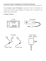
CHAPTER 2 | FEATURES
IR Output Adjustment Controls
Keypad Inputs (6)
Ethernet
RS-232
USB
Power
Supply
RTI COM Port
Expansion Port
IR Emitter Ports (4)
Power/IR
DC Trigger
Outputs (3)
DC Sense
Inputs (3)
Status Light
Ethernet Link
Indicator

13
It’s Under Control
®
CHAPTER 3 | INSTALLATION AND OPERATION
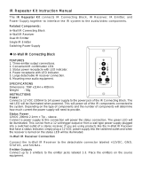
MOUNTING
The MRP-64 can be wall mounted (details below) or free standing. Because
the IR output ports can drive up to 1000 feet of wire, the MRP-64 does not
need to be mounted near the equipment being controlled.
NOTE: Cabling for RS-232 communication should be limited to 50-100ft.
MOUNTING PATTERN
4.8 Inches (122 mm)
8.0 Inches (203 mm)
POWER
The included AC adapter should be connected to the POWER jack on the
MRP-64. The power LED will turn-on and the output LEDs will toggle on
and off in sequence to conrm that the unit is running properly.
POWER/IR TERMINALS AND CONNECTIONS
TERMINAL: +12VDC or +16VDC
Positive power supply connection. It is internally tied to the Power
jack. This can be used to power external IR or RF receivers.
12 or 16 VDC power supply may be used.
Warning: If a 16V power supply is used, trigger outputs and
the IR High Out will be 16V.
TERMINAL: GROUND
Common ground connection. Use this ground reference for any device
that is connected to the +12VDC, SIGNAL IN, OR HIGH OUT terminals.
TERMINAL: SIGNAL IN
Input connection for system trigger codes. This should be connected to
an RTI RF receiver or industry standard IR repeater system.
TERMINAL: HIGH OUT
High current (200mA) IR output connection. This can be used to power
up to 10 infrared mini-emitters, an IR blaster, or extending IR control
over a long distance (1000 ft. max).

Multi-Room Control Processor
MRP-64
14
KEYPAD INPUTS
Six (6) RJ-45
Standard CAT5 cable
Provide power output, IR signal input and RS-485 communication for
any combination of any six RTI keypads (excluding K4 and similar
large in-wall touchpanels which are limited to no more than three).
CONNECTING IR EMITTERS TO OUTPUT PORTS
The IR output ports on the MRP-64 are compatible with industry standard
infrared emitters and infrared repeating systems. Each output port is
capable of driving up to four infrared emitters directly. More than four
infrared emitters requires an amplied connecting block. A connecting
block can be wired up to 1000 feet away from the MRP-64 using #22 AWG
(minimum) wire.
NOTE: The IR output ports on the MRP-64 are NOT compatible with RTI
communication and sensing modules such as the CM-232, VPS-1 and
SPS-1.
ADJUSTING IR OUTPUT GAIN
The IR output gain can be separately adjusted for each of the four output
ports. The MRP-64 is shipped with the IR gain set to the optimum level for
most equipment, and it should only need to be adjusted if the attached
equipment is not responding reliably.
If adjustment is needed, rotate the IR output controls on the front of the
MRP-64 clockwise for higher output power, or counter-clockwise for lower
output power.
INFRARED HIGH OUT
The MRP-64 is compatible with industry standard IR connecting blocks.
Connect the HIGH OUT and GROUND terminals to the signal input and
ground terminals on the connecting block. This is useful if you have many
devices to control, or you want to extend control into other rooms.
This output has short circuit protection, but does not provide a series
resistor for current limiting. It should not be connected directly to IR
emitters.
INFRARED RECEIVERS
The MRP-64 is compatible with all RTI keypads and touchpanels as well as
industry standard IR receivers and repeater systems. Connect the SIGNAL
INPUT, GROUND, and +12VDC (if power is needed) terminals to the signal
out, ground, and power (if needed) terminals of the desired device.
If the MRP-64 sees an incoming system trigger code with a matching zone
ID, it will execute the command or macro associated with that code. The
MRP-64 can be programmed to either block or pass miscellaneous IR data
through its output ports.
CHAPTER 3 | INSTALLATION AND OPERATION

15
It’s Under Control
®
CHAPTER 3 | INSTALLATION AND OPERATION
RF RECEIVERS
The MRP-64 is compatible with RTI RF receiver modules (e.g. RM-433).
Up to 10 RM-433 receiver modules can be connected with a maximum
total wire run of 1000 ft. Follow the guide included with the modules for
installation instructions.
RTI COM
This RJ-45 port allows connection to an RTI ZM-24 Zigbee
®
Transceiver
Module. The connection supports full duplex two-way communication
for use with compatible RTI handheld controllers. Refer to the ZM-24
Transceiver Module operation guide for installation instructions.
EXPANSION PORT
This RJ-45 port provides a convenient connection for receiving IR signals
from in-wall touchpanels through a touchpanel connecting block (CB-4/CB-
8). It also enables two-way serial communication (RS-485) with in-wall
touchpanels or expansion devices such as the RCM-12 (Relay Control
Module).
VOLTAGE TRIGGER OUTPUT
The MRP-64 has three voltage trigger outputs (12VDC @ 100mA) that
are congured within Integration Designer
®
. These voltage triggers are
Normally Off, but they can be programmed to be Normally On (activated)
as long as power is applied to the MRP-64.
Connect the positive lead from the device to one of the three Trig Out
1-2-3 terminals and connect the ground side of the desired device to
the MRP-64 voltage trigger Ground terminal.
VOLTAGE SENSE INPUT
The MRP-64 has three voltage sense inputs (+3-24 VDC) that are
congured within Integration Designer
®
. During the execution of a macro
events can be triggered such as IR commands, RS-232 commands, relay
closure, etc. based on the status of the voltage sense input.
Connect positive lead from voltage source to Sense In 1, 2, or 3
terminal input and negative lead to Ground terminal.
ETHERNET
This RJ-45 port allows connection to a 10/100 Base-T Ethernet network
(LAN) and can be used to download system les to the MRP-64. The
Ethernet Link indicator will be lit red when the MRP-64 is connected to a
LAN.
NOTE: The network settings such as the IP address are congured within
Integration Designer
®
. The initial download of the system le containing
this network information must be done using the USB port, subsequent
downloads may use the Ethernet port.

Multi-Room Control Processor
MRP-64
16
USB PORT
This is a host port for programming updates.
RS-232 PORTS
The MRP-64 is capable of two-way communication via two dedicated
RS-232 ports. Use industry standard cat5 cable with RJ-45 termination
(568B) and two RJ-45 > RS-232 adapters are included if a DB-9
connection is required by the equipment being controlled. The RS-232
transmits on pin #3 of the adapter DB-9, so if the equipment being
controlled receives on pin #2, you will need a null modem adapter
NOTE: RS-232 communication has a distance limitation of 50-100 feet.
DB-9 Connector Pin Out
Pin Signal Signal
Name Description
1 DCD Carrier Detect
2 RXD Receive Data
3 TXD Transmit Data
4 DTR Data Terminal Ready
5 GND Signal Ground/Common
6 DSR Data Set Ready
7 RTS Request To Send
8 CTS Clear To Send
9 NC Not Connected
RJ-45 Connector Pin Out
Pin Signal Signal
Name Description
1 DSR Data Set Ready
2 DCD Carrier Detect
3 DTR Data Terminal Ready
4 GND Signal Ground/Common
5 RXD Receive Data
6 TXD Transmit Data
7 CTS Clear To Send
8 RTS Request To Send
RJ-45 > DB-9 ADAPTER PINOUT
CHAPTER 3 | INSTALLATION AND OPERATION

17
It’s Under Control
®
PROGRAMMING THE MRP-64
The MRP-64 must be programmed to operate. All programming is done
using RTI’s Integration Designer
®
software and is downloaded using the
USB port.
Important Note: The MRP-64 will not respond to trigger codes or execute
commands while the USB cable is attached to a PC. You must detach the
MRP-64 USB port from your PC for normal operation.
The software allows you to create actions (e.g. commands and macros)
that are associated with button presses on one or more RTI remote
controls. The software transparently creates all of the system trigger
codes, and generates the correct download for every device in the
system. Unless you implement some of the software’s advanced
features, programming a system that uses an MRP-64 is just as easy as
programming one that doesn’t.
STATUS LED
The status LED will illuminate Green if a valid system trigger code is
detected. The LED will stay on while the MRP-64 is busy processing the
action associated with the trigger code.
The status LED will icker Green if an invalid system trigger code is
detected. A trigger code is invalid if there is no action associated with it
(i.e. the MRP-64 programming does not match the programming in the
device that is transmitting the trigger code), or if the system zone code
does not match.
The status LED will illuminate Red if the MRP-64 does not contain a valid
program.
The status LED will also illuminate Green to indicate an active USB
connection. A communication problem is indicated if the status LED is
illuminated red while the USB cable is attached to a PC.
SETTING THE ZONE CODE
If the MRP-64 is installed in close proximity to others, the system Zone
Code can be changed in the Integration Designer
®
software. This allows up
to 256 separate control systems to operate in the same general area such
as multi-dwelling units or homes with more than one media system. It is
not necessary to set the Zone Code for RTI Zigbee
®
transceiver modules.
CHAPTER 3 | INSTALLATION AND OPERATION

Multi-Room Control Processor
MRP-64
18
CHAPTER 3 | INSTALLATION AND OPERATION
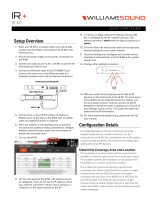
CONNECTION OPTIONS
Zigbee
®
Module
(ZM-24)
RS-232 Controlled
Multi-Zone Receiver
IR Controlled Devices
12VDC Triggered Devices
LAN
IR Receiver
RM-433
Receiver
RTI Keypad RTI Keypad
RTI CB-8
Voltage Status

19
It’s Under Control
®
CHAPTER 4 | SPECIFICATIONS
Power Supply +12 VDC, 4A
Infrared Output Port Four 3.5mm jacks, compatible with industry
standard IR emitters
Infrared Output
Drive
100mA maximum (per port, adjustable)
200mA maximum (high IR output port)
Infrared Frequency
Transmission Range
15kHz - 460kHz
Infrared Input Compatible with industry-standard repeaters and
receivers
Trigger Outputs Three, 12VDC, 100mA max each
Sense Inputs Three, 3-24VDC
RS-232 Ports Two, Bi-directional RJ45 Connections
Ethernet Port 10/100Base-T, RJ45 Connection
USB Ports 1 Programming
Expansion Port RS-485 / IR / Pwr, RJ45 Connection
RTI Com Port Two-way Zigbee
®
Communication Port, RJ45
Connection
Keypad Ports Six, RS-485 / IR/ Pwr
Mounting Wall-mount or free standing
Dimensions
(W x H x D)
11.0” (279mm) x 1.1” (28mm) x 5.7” (145mm)
Weight 2 lb. 13 oz. (944g)
Warranty One Year (Parts & Labor)
All specications subject to change without notice.

Multi-Room Control Processor
MRP-64
20
/