
SERVICE MANUAL
SI : TSE: Check: Approved:
Date Revise Version Description
2007.11.2 V1.0 Initial Issue
2007.11.28 V2.0 Add Appendix A
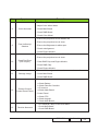
2008.12.19 V3.0
Add in extended models.
Modify “Brightness” spec in chapter 1.
Add in “Forgetting Password” in chapter 3.
Add in “Defect specication table" in chapter 4.
Modify “Serial Number System Denition” in Appendix A.
EP720 Family/EP726 Family
Copyright December, 2008. All Rights Reserved P/N: 36.89U03G001
EP720 Family EP720, EP720i, DS306, DS306i, CB2000, DX720, S22 E, S25, GT-3000,
OPS1900, PV2223+
EP726 Family EP726, EP726i, DX606, DX606i, DX606V, EP726S, EP726V

Condential
EP720 Family/EP726 Family I
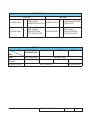
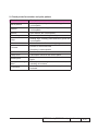
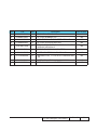
EP720&EP726 Comparison List
EP720 EP726
80.89U01G001 C PCBA MAIN
BOARD FOR EP720 80.89V01G001 B PCBA MAIN BOARD
FOR EP726
48.87K01G001 ADMD Type-X
800x600 PIXEL
0.55” SVGA LVDS
48.87M01G001 ADMD Type-X
1024x768 PIXEL
0.55” XGA LVDS
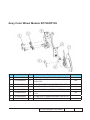
EP726 Family Comparison List
Model
Part
EP726/DX606i/
DX606/EP726i
DX606v EP726v EP726S
DMD 48.87M01G001 48.89B01G001
PCBA MAIN
BOARD
80.89V01G002 80.8CN01G003 80.8CN01G002 80.8CN01G001
POWER CORD 42.50112G001 42.81004G001

EP720 Family/EP726 Family Condential
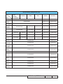
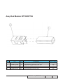
EP720 Family Comparison List
Model
Part
EP720/DS306/
DX720/
OPS1900/
EP720i/DS306i
PV2223+ S22E S25 CB2000 GT-3000
SPEAKER 49.88N03G101 NA 49.88N03G101
IO COVER
LABEL 35.89U01G001 35.89U01G011 35.89U01G021
SCREW
PAN MECH 51.88N11G001 NA 51.88N11G001
MAIN
BOARD
MODULE
80.89U01G002 80.89U01G012 80.89U01G014 80.89U11G002 80.89U01G013
POWER
KEY PC 51.89U02G001 51.89U02G011 51.89U02G011 51.89U02G001 51.89U02G021
TOP
COVER 51.88N06G031 51.88N06G0I1 51.88N06G081 51.88N06G0F1 51.88N06G031 51.88N06G0E1
LED LENS
PC 51.89U03G001 51.89U03G031 51.89U03G011 51.89U03G011 51.89U03G001 51.89U03G011
POWER
CORD 42.50115G001 42.81004G001 42.50112G001
42.53506G001
42.50112G001
42.53506G001 42.50112G001 42.53506G001
BOTTOM
COVER 75.88N07G001 75.88N07G011
ELEVATOR
FOOT PC 51.88N22G001 51.88N22G011
ADJUSTA-
BLE FOOT
RUBBER
52.88N07G001 52.88N07G011
FOCUS
RING
COVER
51.88N10G001 51.88N10G011
IO COVER 51.89U01G001 51.89U01G021
LAMP
COVER
MODULE
70.88N22GR01 70.88N28GR01
ZOOM
RING
COVER
51.88N12G001 51.88N12G011
FOCUS
RING 51.88N04G001 51.88N04G021
ZOOM
RING 51.88N05G001 51.88N05G011
LENS CAP
MODULE 75.88N04G001 75.89F02G001

Condential
EP720 Family/EP726 Family II
Preface
This manual is applied to EP720 Family/EP726 Family projection system. The manual
gives you a brief description of basic technical information to help in service and maintain
the product.
Your customers will appreciate the quick response time when you immediately identify
problems that occur with our products. We expect your customers will appreciate the
service that you offer them.
This manual is for technicians and people who have an electronic background. Please
send the product back to the distributor for repairing and do not attempt to do anything that
is complex or is not mentioned in the troubleshooting.
Notice:
The information found in this manual is subject to change without prior notice. Any
subsequent changes made to the data herein will be incorporated in future edition.
EP720 Family/EP726 Family Service Manual
Copyright December, 2008
All Rights Reserved
Manual Version 3.0

EP720 Family/EP726 Family Condential III
Table of Content
Chapter 1 Introduction
Highlight 1-1
Compatible Mode 1-2
Chapter 2 Disassembly Process
Equipment Needed & Product Overview 2-1
Disassemble Lamp Cover 2-2
Disassemble Lamp Module 2-2
Disassemble Top Cover Module 2-3
Disassemble Keypad Board and Keypad 2-4
Disassemble IR Sensor and Focus Ring Cover 2-4
Disassemble I/O Cover 2-5
Disassemble Sheet Metal and Top Shielding 2-5
Disassemble Main Board Module 2-6
Disassemble Main Board Shielding 2-6
Disassemble Lamp House Shielding 2-7
Disassemble Color Wheel and Photo Sensor Board 2-7
Disassemble Engine Module 2-8
Disassemble DMD Board and DMD Chip 2-8
Disassemble Zoom Ring 2-9
Disassemble Focus Ring 2-9
Disassemble Rod Module 2-10
Disassemble Lamp Driver Module and Fan 2-10
Disassemble LVPS Mudule 2-11
Disassemble Speaker Module 2-11
Disassemble Blower Module & LVPS Sheet Metal Module 2-12

Condential
EP720 Family/EP726 Family IV
Disassemble Limit Switch 2-12
Disassemble Elevator 2-13
Disassemble Adjust Foot 2-13
Rod Adjustment 2-14
Re-write Lamp Usage Hours 2-15
Chapter 3 Troubleshooting
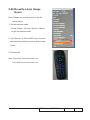
LED Lighting Message 3-1
Main Procedure 3-2
Chapter 4 Function Test & Alignment Procedure
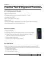
Test Equipment Needed 4-1
Service Mode 4-1
OSD Reset 4-1
Test Condition 4-2
Test Inspection Procedure 4-3
PC Mode 4-4
Video Performance 4-8
Optical Performance Measure 4-9
Others 4-11
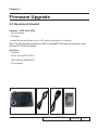
Chapter 5 Firmware Upgrade
Equipment Needed 5-1
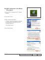
DLP Composer Lite Setup Procedure 5-2
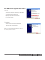
USB Driver Upgrade Procedure 5-4
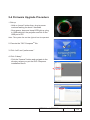
Firmware Upgrade Procedure 5-5

EP720 Family/EP726 Family Condential V
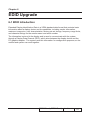
Chapter 6 EDID Upgrade
EDID Introduction 6-1
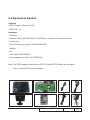
Equipment Needed 6-2
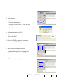
Setup Procedure 6-3
EDID Key-In Procedure 6-3
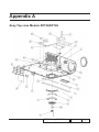
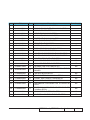
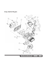
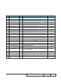
Appendix A Recommended Spare Parts I
Appendix B Serial Number System Denition XXX
PCBA Code Denition XXXII

1-1
Chapter 1
Introduction
1-1 Highlight
No
1
2
3
7
-
10 -
11
12
13

1-2
No
17
20
21
22
23
1-2 Compatible Mode
Analog
72
70

1-3
72
72
70
70

Condential 2-1
EP720 Family/EP726 Family
Chapter 2
Disassembly Process
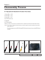
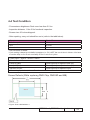
2-1 Equipment Needed & Product Overview
1. Screw Bit (+) :105
2. Screw Bit (+) :107
3. Screw Bit
(-)
:107
4. Hex Sleeves 5 mm
5. Tweezers
6. EP726 projector
* Before you start: This process is protective level II. Operators should wear electrostatic chains.
* Note: - If you need to replace the main board, you have to get into service mode and record the
lamp usage hour.
-The disassembly process for EP720 Family/EP726 Family is the same. Here, we take EP726 as an
example.

Condential 2-2
EP720 Family/EP726 Family
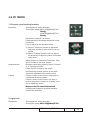
2-3 Disassemble Lamp
Module
1. Unscrew 2 screws then pull out the lamp
module.
2-2 Disassemble Lamp
Cover
1. Unscrew 2 screws to disassemble the
lamp cover.

Condential 2-3
EP720 Family/EP726 Family
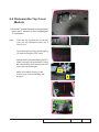
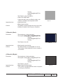
2-4 Disassemble Top Cover
Module
1. Unscrew 7 screws(4 screws on the projector
base and 3 screws on the besides)and
3 connectors.
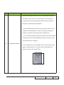
Note: - Push the Top Cover(as the red arrow)
then pull up it.Because there are 8
tenons on it.
- Avoid damage by pulling and dragging
IR cable and keypad FPC cable.
- Hold the CNNT plug when pulling the FPC
cable is strongly recommended. Pulling
the cable directly from the projector will
cause the cable damages.
- Make sure cables are plug in the
correct ports when assembling the
projector.

Condential 2-4
EP720 Family/EP726 Family
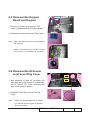
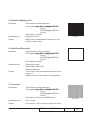
2-5 Disassemble Keypad
Board and Keypad
1. Unscrew 3 screws and unplug 1 FPC
Cable to disassemble the Keypad Board.
2. Separate the Keypad from the Top Cover.
Note: - Take care the two tenons when separating
the Keypad.
.
- Make sure cables plug into the correct
ports when assembling the projector.
2-6 Disassemble IR Sensor
and Focus Ring Cover
1. Use tweezers to take off the black lm
tape,then press two tenons to disassemble
the IR Sensor.The other disassemble
way is the same as above.
2. Separate Focus Ring Cover from Top
Cover.
Note: - When you disassemble the IR Sensor,
you should use two ngers to parallel
pull out the hook.

Condential 2-5
EP720 Family/EP726 Family
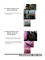
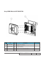
2-7 Disassemble I/O Cover
1. Unscrew 2 hex screws (on the Rear
Cover).
2. Unscrew 2 screws (on the Top Shielding).
2-8 Disassemble Sheet Metal
and Top Shielding
1. Unscrew 1 screw to disassemble Sheet
Metal.
2. Unscrew 1 screw to disassemble Top
Shielding.

Condential 2-6
EP720 Family/EP726 Family
2-9 Disassemble Main Board
1. Uscrew 1 screw (as red circle).
2. Unplug 8 connectors.
Note: - Unplug 6 connectors(as yellow
squares), then push the Main Board
as the red arrow,at last unplug the
connector (as green square).
- Make sure cables plug into the correct
ports when assembling the projector.
2-10 Disassemble Main Board
Shielding
1. Unscrew 5 screws to disassemble Main
Board Shielding.

Condential 2-7
EP720 Family/EP726 Family
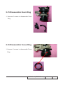
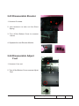
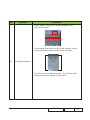
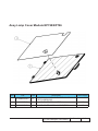
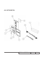
2-12 Disassemble Color
Wheel and Photo
Sensor Board
1. Unscrew 2 screws (as red circle)
to disassemble Color Wheel Module.
2. Unscrew 1 screw from Color Wheel Module
(as blue circle) and take out the Photo
Sensor Board.
2-11 Disassemble Lamp
House Shielding
1. Unscrew 4 screws to disassemble Lamp
House Shielding.

Condential 2-8
EP720 Family/EP726 Family
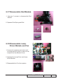
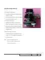
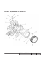
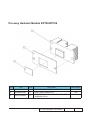
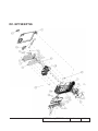
2-13 Disassemble Engine
Module
1. Unscrew 4 screws to disassemble Engine
Module.
2-14 Disassemble DMD Board
and DMD Chip
1. Unscrew 2 screws to disassemble DMD
Module and Heat Sink.
2. Unlock the lockhole by Screw Bit (-) to
disassemble the DMD Chip from the DMD
Board.
Note: - Avoid damage by touching the DMD
Chip.

Condential 2-9
EP720 Family/EP726 Family
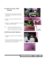
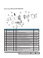
2-15 Disassemble Zoom Ring
1. Unscrew 2 screws to disassemble Zoom
Ring.
2-16 Disassemble Focus Ring
1. Unscrew 3 screws to disassemble Focus
Ring.

Condential 2-10
EP720 Family/EP726 Family
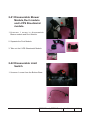
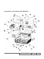
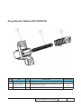
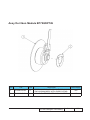
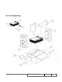
2-17 Disassemble Rod Module
1. Unscrew 3 screws to disassemble Rod
Module.
2. Separate Rod Spring and Rod.
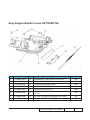
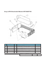
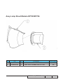
2-18 Disassemble Lamp
Driver Module and Fan
1. Unscrew 4 screws(as red circle) and 1
connector(as blue circle) to take out the
Lamp Driver from Bottom Cover.
2. Separate the Lamp Driver and Lamp
Driver Bracket.
3. Disassemble the Fan from system.
Page is loading ...
Page is loading ...
Page is loading ...
Page is loading ...
Page is loading ...
Page is loading ...
Page is loading ...
Page is loading ...
Page is loading ...
Page is loading ...
Page is loading ...
Page is loading ...
Page is loading ...
Page is loading ...
Page is loading ...
Page is loading ...
Page is loading ...
Page is loading ...
Page is loading ...
Page is loading ...
Page is loading ...
Page is loading ...
Page is loading ...
Page is loading ...
Page is loading ...
Page is loading ...
Page is loading ...
Page is loading ...
Page is loading ...
Page is loading ...
Page is loading ...
Page is loading ...
Page is loading ...
Page is loading ...
Page is loading ...
Page is loading ...
Page is loading ...
Page is loading ...
Page is loading ...
Page is loading ...
Page is loading ...
Page is loading ...
Page is loading ...
Page is loading ...
Page is loading ...
Page is loading ...
Page is loading ...
Page is loading ...
Page is loading ...
Page is loading ...
Page is loading ...
Page is loading ...
Page is loading ...
Page is loading ...
Page is loading ...
Page is loading ...
Page is loading ...
Page is loading ...
Page is loading ...
Page is loading ...
Page is loading ...
Page is loading ...
Page is loading ...
Page is loading ...
Page is loading ...
Page is loading ...
-
 1
1
-
 2
2
-
 3
3
-
 4
4
-
 5
5
-
 6
6
-
 7
7
-
 8
8
-
 9
9
-
 10
10
-
 11
11
-
 12
12
-
 13
13
-
 14
14
-
 15
15
-
 16
16
-
 17
17
-
 18
18
-
 19
19
-
 20
20
-
 21
21
-
 22
22
-
 23
23
-
 24
24
-
 25
25
-
 26
26
-
 27
27
-
 28
28
-
 29
29
-
 30
30
-
 31
31
-
 32
32
-
 33
33
-
 34
34
-
 35
35
-
 36
36
-
 37
37
-
 38
38
-
 39
39
-
 40
40
-
 41
41
-
 42
42
-
 43
43
-
 44
44
-
 45
45
-
 46
46
-
 47
47
-
 48
48
-
 49
49
-
 50
50
-
 51
51
-
 52
52
-
 53
53
-
 54
54
-
 55
55
-
 56
56
-
 57
57
-
 58
58
-
 59
59
-
 60
60
-
 61
61
-
 62
62
-
 63
63
-
 64
64
-
 65
65
-
 66
66
-
 67
67
-
 68
68
-
 69
69
-
 70
70
-
 71
71
-
 72
72
-
 73
73
-
 74
74
-
 75
75
-
 76
76
-
 77
77
-
 78
78
-
 79
79
-
 80
80
-
 81
81
-
 82
82
-
 83
83
-
 84
84
-
 85
85
-
 86
86


Optoma Optoma DX606v User manual
- Category
- Data projectors
- Type
- User manual
Ask a question and I''ll find the answer in the document
Finding information in a document is now easier with AI
Related papers
-
Optoma PICO PK201 User manual
-
Optoma EX774 Serivce Manual
-
Optoma THD2080 Operating instructions
-
Optoma DX609 User manual
-
-
Optoma HD80-LV User manual
-
Optoma EX762 User manual
-
Optoma TX7156 User manual
-
Optoma EP774 User manual
-
Other documents
-
Acer X110 User manual
-
August EP720 User manual
-
 Euro-Pro EP720 User manual
-
Syng Cell Alpha Immersive Speaker User guide
-
V7 VPL1774-1E Datasheet
-
Toshiba kV-9168A User manual
-
Sanyo PJLINK PDG-DXL100 User manual
-
-
BenQ PB6100 User manual
-
