
Rev. 01
Company Confidential Optoma_______________________ Delta____________
1 2007/06/13
Service Manual
DLP Digital Projector
Model Name : EP774/TX774

Rev. 01
Company Confidential Optoma_______________________ Delta____________
2 2007/06/13
Revision Description Date
00 Preliminary 06/01/2007
01 Specification(Contrast Ratio & Brightness) revised (Pg5)
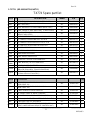
Spare parts list revised (Pg70—Pg72)
The views of the IO label revised (Pg9) 06/13/2007

Rev. 01
Company Confidential Optoma_______________________ Delta____________
3 2007/06/13
CONTENTS
1.COMPLIANCE OF SAFE REPAIR........................................................... 4
1-1.Cautions During Disassembling And Assembling......................... 4
1-2.Lamp.......................................................................... 4
1-3.Lens................................................................... 4
2.SPECIFICATIONS........................................................... 5
2-1.Product Specifications...................................................... 5
2-2.Input/output connectors.................................................. 9
2-3.Description of Wire Connection............................................10
2-3-1 Accessories List ………………………………………………………………………………10
2-3-2 Accessories Wire Description …………………………………………………………10
2-4.Remote Control keypad...................................................... 13
2-5. Control Key Pad and LED..................................................................... 14
2-6.BLOCK DIAGRAM........................................................... 15
3.TROUBLE SHOOTING........................................................... 16
4.DISASSEMBLY AND ASSEMBLY........................................................... 20
5.Firmware................................................................ 28
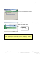
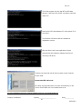
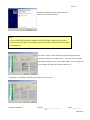
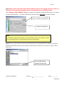
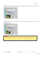
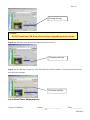
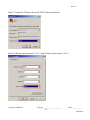
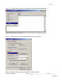
5-1.Projector USB Drivers Installation Guide.................................................28
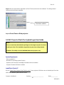
5-2.DLP Projector Flash-Tool (firmware) User Guide............................….37
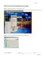
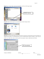
5-3.DLP Projector Flash-Tool (splash logo) User Guide........................................42
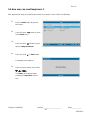
5-4.How user can reset lamp hours .................................................48
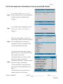
5-5.Check Lamp hours information in Service mode (J4P Series).....................49
5-6.Overscan rate............................................................................50
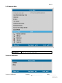
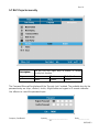
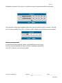
5-7.DLP Projector security............................................................................52
5-8.DLP Projector security unlock (Optoma EP774 series)..............................54
6.How To Program By RS232........................................................... 57
7.SERVICE NOTE........................................................... 65
7-1.Cleaning...................................................................... 65
7-2.Remote Control For Battery Replacement.............................. 66
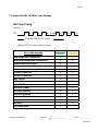
7-3.Power & READY LED Blink Code Message.......................…. 67
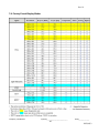
7-4.Factory Preset Display Modes................................................. 68
7-5.OPTOMA Splash LOGO screen.........................................................69
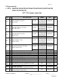
7-6.Spare parts list ......................................................................... 70
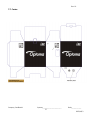
7-7.Carton.................................................................................75

Rev. 01
Company Confidential Optoma_______________________ Delta____________
4 2007/06/13
1. COMPLIANCE OF SAFE REPAIR
Be sure to read this Service Manual before providing services. In the projector, full consideration is taken
to ensure the safety for a fire, electric shock, injury, harmful radiation, and substance. Therefore, observe the
notice described in this Service Manual so that the safety is kept when providing services. Moreover, be sure to
observe the notice described in the Instruction Manual.
Pay attention to the following during service inspection.
1-1. Cautions during disassembling and assembling
1.This equipment contains parts under high voltage. When making repairs, etc. Be sure to pull out the power
plug beforehand to insure safety.
2. Parts may be very hot immediately after use. Make sure the equipment has cooled off sufficiently before
carrying out repairs.
3. Make sure that parts and screws and wiring, etc. are returned to their original positions. Tube, tape and
other insulation materials have been used for safety reasons. The internal wiring has been designed to
avoid direct contact with hot parts or parts under high voltage when using clamps or other tools.
4. The parts used in this device have special safety features such as flame-resistance and anti-voltage
properties. When replacing parts, always use parts supplied from the factory.
5. After finishing operations make sure that all parts and wires have been returned to their original position
and that there has been no deterioration of the area around the location that was worked on.
6. Be sure to use an earth band (wrist band) during repair and inspection.
1-2. Lamp
During current conduction, the lamp is in the high-temperature state. In this case, pay careful attention because
a high voltage is used. When replacing a lamp, replace it after confirming that the lamp has gotten
cold sufficiently.
1-3. Lens
Do not look through a lens during projection. This damages your eyes.

Rev. 01
Company Confidential Optoma_______________________ Delta____________
5 2007/06/13
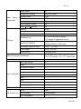
2. SPECIFICATIONS
2-1. Summary Specifications
Design Specification "TI" DMD, 0.7" x 1, 12∘, XGA
Technology DDR DLP with DDP2000
Engine System Delta non-telecentric optical engine J4P
Native XGA 1024x768 Native
Resolution Compatibility Up to SXGA 1280x 1024 @ 75 Hz <140MHz >
Typical 2100:1
Contrast Ratio* Minimum 1900:1
Typical/Minimum (Standard mode)3500/3200 ANSI Lumens
Brightness* Typical/Minimum (ECO mode) 2800 /2500ANSI Lumens
Typical 80%
Minimum 70%
Brightness
Uniformity Test Method average 4 corners / center at 9 points
Color Reproduction 24 bit, 16.7million True Color
Color Temperature @ normal 6000K
Color Wheel 5-Segment, RYGWB (2x)
R/G/B/W/Y :82/80/78/91/29
44mm
Projection Lens Manual Zoom and Focus
Digitial Zoom yes
Zoom Ratio 1.15:1
Projection Distance 1m to 11.2m
Projection Screen Size (diagonal) 23.4"~300"
Projection Method Front/Rear, Desktop/Ceiling (Rear, Front)
Throw Ratio Distance/Screen Width 1.8(Wide) - 2.1(Tele)
Effective Focal length 26.01 ~ 29.84mm; 2m @54"
Image Distortion +/- 1 % max
Optical Offset 124%
Aspect Ratio 4:3 & 16:9
* Note: DELTA will confirm the final figure after 1st MP shipment

Rev. 01
Company Confidential Optoma_______________________ Delta____________
6 2007/06/13
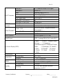
Keystone Correction +/- 15°(Angle from optical axis)
H-Sync 15, 31~90KHz
Frequency V-Sync 50 - 85 Hz
VESA 640x480@60/72/75 Hz
VESA 640x480@ 85Hz
VESA 800x600@56/60/72/75/85Hz
VESA 1024x768@ 60/70/75/85 Hz
RGB Digital
VESA 1280x1024@ 60Hz
VESA 1024x768@85/75/72/70/60 Hz
VESA 800x600@85/75/72/60/56 Hz
VESA 640x480@85/75/72/60 Hz
VESA 1280x1024@60 Hz
RGB Analog
Super VGA, VGA
Macintosh (13", 16" , 19" )
Macintosh Power Mac
SDTV 480i,576i (thru RGB HD-15)
EDTV 480p (thru RGB HD-15)
HDTV 576i,720p,1080i (thru RGB HD-15 )
Compatibility
Video NTSC/NTSC 4.43, PAL( B/G/H/I/M/N 60),
SECAM
Type Osram E20.6
Standard mode 280W
ECO Mode 230W
Lamp Life for Standard mode 2000 hours
Lamp Life for ECO mode 3000 hours
Lamp
Survival Rate 50%0
Fan Number 4
Acoustic Noise (normal) Typical 36dB / max 37dB
Thermal Acoustic Noise (ECO) Typical 33dB / max 34dB

Rev. 01
Company Confidential Optoma_______________________ Delta____________
7 2007/06/13
Power Switch Yes
Voltage(auto-ranging) Typical @ 110Vac
Standard mode 350W
ECO Mode 230W
Standby (watts) <5W
Auto-Ranging Function Yes
Power Supply &
Consumption
Power Factor Correction Yes
Material Plastic
Ceiling Mount Yes & with tripod mount
Handle NA
Adjustment Leg Yes, 1 at front center, 9 degree
(-1~3 degree tilt adjustable at side)
Dimensions (WxDxH) 11.81” x 9.61” x 3.95”
(300mm x 244mm x 100.5mm)
Net Weight (Projector Only) 3.7Kg ( ≦8.2 lbs)
Gross Weight 6.6Kg(≦14.6 lbs)
ID Design
Security Lock Kensington Lock
Safety & Regulatory Compliance FCC-B / UL / c-UL / TUV / CB / CE / CCC /
ICES-003 (class B) / eK, CCC, China RoHS
Key Pad Function Yes
Back Light Design NA
Power V
Ez Key/Quick Menu NA
Auto V
Source V
Keystone V (share with up/down)
Menu V
Enter V
Volume (-/+) V (share with left/right)
Key Pad Definition
Arrow Key +/-/up/down V
LED Indicator Design Yes
Power Green
Lamp Standby Orange(Amber)
LED Define/Color Over Temperature NA

Rev. 01
Company Confidential Optoma_______________________ Delta____________
8 2007/06/13
Data input -I DVI-I connector accept DVI-D signal
Data input -II RGB HD-15
Video Composite Video (RCA x 1)
S-Video S-Video (Mini DIN)
Component Yes, thru RGB HD-15
HDMI Digital Video DVI-D + HDCP
Audio input - I (RCA R& L) Yes
INPUT Terminals
Audio input -II (Mini Jack) Yes (mini jack)
Data output RGB HD-15 OUTPUT
Terminals Audio Output Yes (mini jack) -variable adjustment
Control : USB Yes (USB-B mouse + keypad emulation +
Flash upgrade )
Control: RS-232 Yes (Room Control)
Control Terminals
Screen Control Yes, 12V
Build-in Speaker 3 w mono speaker (SPL <= 5W)
Plug & Project EDID1.3, analog RGB & DVI-D (with HDCP)
On-Screen Display (OSD)
1.English 2.French 3.Spanish (Span)
4.German 5.Portuguese
6.Simplefied Chinese 7.Traditional Chinese
8.Italian 9. Norwegian, 10. Swedish
11. Dutch 12. Russian 13. Korean
14. Finnish 15. Greek 16. Danish
17. Polish
Environmental
Non-Operating -10°C ~ 60°C
Temperature Operating 5° ~ 40°C @ sea level
Non-Operating sea level to 40,000 feet
Altitude Operating sea level to 10,000 feet (@23C)
Non-Operating 5% to 95%
Humidity Operating 5% to 90% with maximum wet bulb
temperature of +27°C

Rev. 01
Company Confidential Optoma_______________________ Delta____________
9 2007/06/13
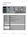
2-2 Input/output connectors
EP774/TX774
RGB (Analog) HD-15 x1(I/P), HD-15 x1(O/P),
DVI-D With HDCP Yes
Video (CVBS) Composite video (RCAx1)
S-Video (Y/C) Mini-DIN
Component Video VGA to Component thru (HD-15_RGB)
Audio in (Video) Left/Right (RCA x2)
Audio in (PC) Mini-phone jack (3.5mm)
Audio out(PC) Mini-phone jack (3.5mm)
DC Power output 12v Yes
Service/ Firmware
upgrades USB
Remote Mouse Control USB
Yes
N/A
Serial Port(RS-232) N/A
Security Kensington slot

Rev. 01
Company Confidential Optoma_______________________ Delta____________
10 2007/06/13
2-3. Description Of Wire Connection
2-3-1 Accessories List
1. AC Power Cord x 1 ( US 3.0M)
2. Computer Cable VGA to VGA (2.0m)
3. USB Cable, A to B (2.0m)
4. Composite cable RCA * 1 (1.8m)
5. WEEE card
6. Remote Controller with laser pointer & batteries
7. QTG(10 language: English, French, German, Spanish, Italian, Portuguese,
Russian, Simplified Chinese, Traditional Chinese, Korean
8. CD (Info file , cover artwork as DLP generic)
9.Carrying case with Optoma Logo
10. Lens cap (slide door design, Emboss Eyes Warning label, optoma's designed logo)
11. Warranty card
12.User’s Manual in 18 language ( English, French, German, Italian, Spanish, Portuguese,
Russian, Simplified Chinese, Traditional Chinese, Korean,Dutch, Swedish, Finnish,
Greek, Danish, Norwegian, Polish, Arabic )(CD only)
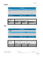
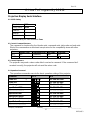
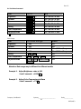
2-3-2 Accessories Wire Description
USB Cable (2.0m) 3080337300
SHELL DRAIN SHELL
4 BLACK 4
3 GREEN 3
2 WHITE 2
1 RED 1
J2 WIRE COLOR J2
WIRE CONNECTION TABLE

Rev. 01
Company Confidential Optoma_______________________ Delta____________
11 2007/06/13
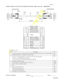
CABLE SIGNAL D-SUB D-SUB L2000 BLK (RGB CABLE 2m) P/N:3080425001

Rev. 01
Company Confidential Optoma_______________________ Delta____________
12 2007/06/13
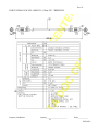
CABLE SIGNAL RCA RCA L1800 YEL (1.8m) P/N:3080301101

Rev. 01
Company Confidential Optoma_______________________ Delta____________
13 2007/06/13
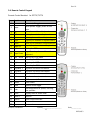
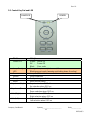
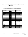
2-4. Remote Control Keypad
Remote Control Handset for EP774/TX774
Key Function Description
1 Power Power on/off toggle
2 Laser Laser pointer trigger, press to emit
laser
3 Up Up key for emulation of keyboard move
4 Left Left key for emulation of keyboard move
5 Enter Enter key for emulation of keyboard move
6 Right Right key for emulation of keyboard move
7 Down Down key for emulation of keyboard move
8 Page Up Page Up key for emulation of keyboard
9 Up arrow Up key for OSD menu
10 Page Down Page Down key for emulation of
keyboard
11 Left arrow Left key for OSD menu
12 Enter Enter key for OSD menu
13 Right arrow Right key for OSD menu
14 Down arrow Down key for OSD menu
15 Keystone + Keystone correction increment
16 Keystone - Keystone correction decrement
17 Volume - Speaker volume decrement
18 Volume + Speaker volume increment
19 Menu OSD menu on/off
20 Status Show status
21 Mute Speaker mute toggle
22 Auto Auto adjustment for phase, tracking,
size, position
23 Blank Display blank & Audio mute
24 Zoom + Zoom in
25 Source Input source selection
26 Freeze Freeze video
27 Zoom - Zoom out

Rev. 01
Company Confidential Optoma_______________________ Delta____________
14 2007/06/13
2-5. Control Key Pad and LED
Name Usage
Power LED Green: Power On
Off : Power Off
Blink : Error code
Lamp Ready
LED Orange: Lamp is ready to turn on/off
Blink:Lamp not ready (warming up/shutting down & cooling)
Power Lamp On/Off switch
Source Source selection
Re-sync Re-Sync image perfection
Menu Menu On/Off switch
Keystone+ (Up) Keystone + when OSD off
Up selection when OSD on,
Keystone- (Down) Keystone – when OSD off
Down selection when OSD on,
Vol+ (Right) Volume + when OSD off
Right selection when OSD on
Vol- (Left) Volume - when OSD off
Left selection when OSD on
LAMP LED POWER

Rev. 01
Company Confidential Optoma_______________________ Delta____________
15 2007/06/13
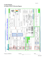
2-6. Block Diagram
OPTOMA EP774/TX774 Structure Diagram

Rev. 01
Company Confidential Optoma_______________________ Delta____________
16 2007/06/13
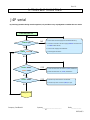
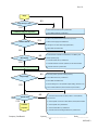
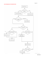
3. TROUBLE SHOOTING
J4P serial
By checking operations during normal usage time, it is possible to carry out judgments on malfunction to a certain
1. Check cable of Power Supply Unit and thermostat Ass’y.
2. Check the connection of Power Supply (CON201 of Power board
to CN900 of Main board).
3. Check Power Supply Unit malfunction.
4. Check keypad connection.
YES
NO
NO
Connect the power cord
POWER: Light
1.Check Thermal sensor1 Transistor ( Q702 ) malfunction.
2.Check Thermal sensor IC ( U709 ) malfunction.
POWER、READY:ON
POWER: 4 Blinks
READY: 1 Blink
Waiting Power On
YES
NO
YES
POWER: 7 Blinks
NO
1. Check Lamp Cover Switch is not attached.
2. Check Lamp Cover connector (CN12) is open.
YES

Rev. 01
Company Confidential Optoma_______________________ Delta____________
17 2007/06/13
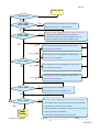
Turn the power ON
The lamp is ON
POWER: 4 Blinks
Ready: 1 BLINKS
POWER: 5 Blinks
Ready: 1 BLINKS
POWER: 6 Blinks
Lamp does not light:lighting operation sound (ignition sound) exists.
1. Check Main Board and Ballast Board Ass’y malfunction.
2. Check Ballast to Main board connector (CN530) disconnected.
3. Check Lamp failure (Lamp is broken, damaged, or burst).
1. Check Main board connector (CN800) of Fan disconnected.
2. Check Lamp Fan malfunction.
1. Check Main board connector (CN801) of Fan disconnected.
2. Check Ballast Fan malfunction.
1. Check Main board connector (CN9050) of Fan disconnected.
2. Check Burner fan malfunction.
1. Check Main board connector (CN800) of Fan disconnected.
2. Check Power fan malfunction.
Lamp does not light:No lighting operation sound (ignition sound) exists.
1. Check Flexible cable of Color Wheel Ass’y is disconnected and broken.
2. Color Wheel Ass’y malfunction (does not rotate).
3. Check Main Board Ass’y malfunction (Color Wheel Ass’y does not rotate).
4. Check Power Supply Unit malfunction.
5. Check Index board malfunction (color wheel turns fast).
YES
YES
READY:1 Blink
READY:2 Blink
READY:3 Blink
READY:4 Blink
POWER: 3 Blinks
POWER: 9 Blinks
Image
Display
YES
YES
YES
NO
NO
NO
NO
NO
1.Check Thermal sensor1 Transistor ( Q702 ) malfunction.
2.Check Thermal sensor IC ( U709 ) malfunction.
1. Check Thermostat is not attached.
2. Check Main board connector (CN852) is open.
NO

Rev. 01
Company Confidential Optoma_______________________ Delta____________
18 2007/06/13
Image
Projector logo screen
Confirmation with none-signal state 1. Check CW Sensor Board Ass’y malfunction.
2. Check Main Board Ass’
y
malfunction.
1. Check Lamp deterioration (malfunction/usage time).
2. Check Power Supply Unit malfunction.
(No change occurs even after lamp replacement.)
3. Check DMD Set malfunction.
1. Check Remote controller set malfunction, Low battery, and
outside operating rang.
2. Check Main Board Ass’y malfunction.
3. Check Main board connector (CN451) & U451 disconnected.
4. Check IR PWB Ass’
y
malfunction.
1. Check the pattern generator setting is wrong.
2. Check Main Board Ass’y malfunction.
3. Check DMD Set malfunction.
4. Check Setting on PC side (external output setting, resolution, etc.)
5. Check Cable malfunction (disconnection and pins broken).
1. Check Wire from IO board ( CN8 ) to Main board (CN705)
disconnected.
2. Check Speaker Connector to Main board (CN704) disconnected.
3. Check Speaker Ass’y malfunction.
4. Check Audio PWB Ass’y malfunction.
5. Check Main Board and keypad Board Ass’y malfunction.
Still dark after the
Menu display
Input each signal
Image display
Speaker work
Check the
projection
NO
YES
NO
NO
NO
YES
NO
YES
YES
YES

Rev. 01
Company Confidential Optoma_______________________ Delta____________
19 2007/06/13
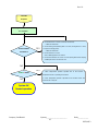
Check the
Projection
Check using all black/white screens with
PC connection
Are abnormalities
noticeable on
1. Check Black lines on screen (horizontal and vertical).
→ DMD Set malfunction.
2. Check Missing pixels (Missing white: 1 or more, missing black: 5 or more,
or sequence missing pixels).
→ DMD Set malfunction.
3. Check Shadows on screen.
→ Dirt on DMD/projection lens surface.
4. Check Bluish shadows on corners of screen (during white screen display).
→ Shifted optical axis of Lens Base Unit.
POWER: 3 Blinks 1. Check Temperature protector operated due to the increase in
temperature based on operating environment
2. Check Temperature protector operated due to blocked suction and
exhaust holes or dirty fan
System OK
Normal operation
YES
YES
NO
NO

Rev. 01
Company Confidential Optoma_______________________ Delta____________
20 2007/06/13
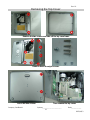
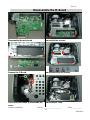
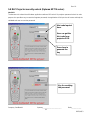
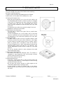
4. DISASSEMBLY AND ASSEMBLY
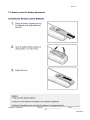
Removing the Lamp Module and Lamp Cover
Look at Top Case side Loose the two screws.
Open the lamp cover Loose the two screws and then take out
the lamp module by the ring-pull.
Lamp module views.
Lamp holder views.
Page is loading ...
Page is loading ...
Page is loading ...
Page is loading ...
Page is loading ...
Page is loading ...
Page is loading ...
Page is loading ...
Page is loading ...
Page is loading ...
Page is loading ...
Page is loading ...
Page is loading ...
Page is loading ...
Page is loading ...
Page is loading ...
Page is loading ...
Page is loading ...
Page is loading ...
Page is loading ...
Page is loading ...
Page is loading ...
Page is loading ...
Page is loading ...
Page is loading ...
Page is loading ...
Page is loading ...
Page is loading ...
Page is loading ...
Page is loading ...
Page is loading ...
Page is loading ...
Page is loading ...
Page is loading ...
Page is loading ...
Page is loading ...
Page is loading ...
Page is loading ...
Page is loading ...
Page is loading ...
Page is loading ...
Page is loading ...
Page is loading ...
Page is loading ...
Page is loading ...
Page is loading ...
Page is loading ...
Page is loading ...
Page is loading ...
Page is loading ...
Page is loading ...
Page is loading ...
Page is loading ...
Page is loading ...
Page is loading ...
-
 1
1
-
 2
2
-
 3
3
-
 4
4
-
 5
5
-
 6
6
-
 7
7
-
 8
8
-
 9
9
-
 10
10
-
 11
11
-
 12
12
-
 13
13
-
 14
14
-
 15
15
-
 16
16
-
 17
17
-
 18
18
-
 19
19
-
 20
20
-
 21
21
-
 22
22
-
 23
23
-
 24
24
-
 25
25
-
 26
26
-
 27
27
-
 28
28
-
 29
29
-
 30
30
-
 31
31
-
 32
32
-
 33
33
-
 34
34
-
 35
35
-
 36
36
-
 37
37
-
 38
38
-
 39
39
-
 40
40
-
 41
41
-
 42
42
-
 43
43
-
 44
44
-
 45
45
-
 46
46
-
 47
47
-
 48
48
-
 49
49
-
 50
50
-
 51
51
-
 52
52
-
 53
53
-
 54
54
-
 55
55
-
 56
56
-
 57
57
-
 58
58
-
 59
59
-
 60
60
-
 61
61
-
 62
62
-
 63
63
-
 64
64
-
 65
65
-
 66
66
-
 67
67
-
 68
68
-
 69
69
-
 70
70
-
 71
71
-
 72
72
-
 73
73
-
 74
74
-
 75
75


Ask a question and I''ll find the answer in the document
Finding information in a document is now easier with AI
Related papers
Other documents
-
ROOMS TO GO 23013232 Assembly Instructions
-
Acer X110 User manual
-
Hitachi CP-DX300 guide User manual
-
Hitachi CP-X440 series User manual
-
promethean PRM-25 User guide
-
Sanyo PJLINK PDG-DXL100 User manual
-
promethean PRM-32 Owner's manual
-
-
-