Page is loading ...

1Functions WMA-12
2Parallel Operation WMA-13
1.1 Input Voltage Range
1.2 Inrush Current Limiting
1.3 Overcurrent Protection
1.4 Overvoltage Protection
1.5 Thermal Protection
1.6 Output Ripple Noise
1.7 Output Voltage Adjustment Range
1.8 Isolation
1.9 Low Power Consumption
WMA-12
WMA-12
WMA-12
WMA-12
WMA-12
WMA-12
WMA-13
WMA-13
WMA-13
3Life Expectancy and Warranty WMA-13
5.1 Outline of Options
5.2 Terminal block cover
5.3 Medical Isolation Grade
5.4 Others
4Ground WMA-13
5Options and Others WMA-13
WMA-13
WMA-14
WMA-14
WMA-14
April 19, 2023
AC-DC Power Supplies Medical Type
Instruction Manual
WMA-11
WMA

1.1 Input Voltage Range
■Power factor correction is not built-in.
■If the input voltage is outside the rated range, the power supply
may malfunction operate in accordance with the specifications
and/or start hunting or fail.
■If the input voltage changes suddenly, the output voltage may go
outside the specifications. Consult us for more details.
■The power supply can work at the input voltage dip with the de-
rating (Excluding WMA350H).
Table 1.1 SEMI F47-0706 Maximum output load factor
Voltage Dip duration
[ms] WMA35F WMA75F WMA150H
200VAC→100VAC
200 100% 100% 90%
200VAC→140VAC
500 100% 100% 100%
200VAC→160VAC
1000 100% 100% 100%
●WMA35F WMA75F
■The range is from 85VAC to 264VAC
In cases that conform with safety standard, input voltage range is
100VAC to 240VAC (50/60Hz).
● WMA150H WMA350H
■The rated input voltage range of the power supply is A85VAC-
132VAC/170VAC-264VAC. (See SPECIFICATIONS for more details).
■To comply with the safety standards, use the power supply with the
input voltage range of 100VAC-120VAC/200VAC-240VAC (50/60Hz).
1.2 Inrush Current Limiting
■Inrush current protection is built-in.
■If you need to use a switch on the input side, select one that can
withstand an input inrush current.
■Thermistor is used in the inrush current limiting circuit. When
you turn the power supply on and off repeatedly, have enough
intervals for the power supply to cool down before being turned
on again.
1.3 Overcurrent Protection
■Overcurrent protection is built-in. It works at more than 105% of
the rated output current. The power supply recovers automati-
cally when the overcurrent condition is removed. Do not use the
power supply under a short-circuit or overcurrent condition.
■Hiccup Operation Mode
When overcurrent protection works and the output voltage drops,
the output voltage goes into Hiccup mode so that the average
output current can decrease.
1.4 Overvoltage Protection
■Overvoltage protection is built-in.
Remarks : Please avoid applying a voltage exceeding the rated
voltage to an output terminal. Doing so may cause a power sup-
ply to malfunction or fail.
If you cannot avoid doing so, for example, if you need to operate
a motor, etc., please install an external diode on the output ter-
minal to protect the unit.
●WMA35F WMA75F WMA150H
■If the overvoltage protection circuit is activated, shut down the input
voltage, wait at least 3 minutes and turn on the AC input again to re-
cover the output voltage. Recovery time varies depending on such
factors as input voltage value at the time of the operation.
●WMA350H
■The unit automatically recovers when the fault condition is removed.
1.5 Thermal Protection
●WMA350H
■Thermal protection is built-in.
Thermal protection will work under the following conditions and
the power supply will shut down.
①When the operating temperature and the output current great-
ly exceed the derating curve.
②When the built-in cooling fan stops or the air flow from the fan
is obstructed.
If thermal protection works, switch off the input voltage and elim-
inate the conditions causing thermal protection to work. Allow
enough time for the unit to cool off before switching on the input
voltage again to recover the output voltage.
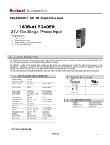
1.6 Output Ripple Noise
■Output ripple noise may be influenced by the measuring environment.
The measuring method shown in Fig. 1.1 is recommended.
Fig.1.1 Measuring method of Ripple Noise
Remarks : When measuring output ripple noise with an oscil-
loscope, do not let the oscilloscope’
s GND cable cross the
magnetic flux from the power supply. Otherwise there may be
electrical potential generated on the GND cable and the measur-
ing result may not be accurate.
Bad example Good example
Fig.1.2 Example of measuring output ripple noise
1 Functions
㻯㻝㻌㻦 Film capacitor 0.1䃛F
㻯㻞㻌㻦㻌Aluminum electrolytic capacitor 47䃛F
+Vout
-Vout
Load
150mm
C
2
C
1
Osilloscope/
Ripple noise meter
Bw:20MHz
Differential probe
+
150mm
Power
Supply
Probe
Power
Supply
Differential probe
April 19, 2023
AC-DC Power Supplies Medical Type Instruction Manual
WMA-12
WMA

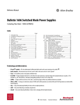
2 Parallel Operation
■Redundant operation is possible by wiring as shown below.
Fig.2.1 Example of redundancy operation
■Even a slight difference in output voltage can affect the balance
between the values of I1 and I2.
Make sure the value of I3 does not exceed the rated output cur-
rent of the power supply.
I3≤the rated current value
■Parallel operation is not possible.
I2
I1I3
-
+
+
-
Power
Supply
Load
Power
Supply
1.7 Output Voltage Adjustment Range
■The output voltage can be adjusted within the specified range by
turning the built-in potentiometer clockwise (up) or counterclock-
wise (down).
■Please operate the potentiometer slowly.
1.8 Isolation
■For a receiving inspection, such as Hi-Pot test, gradually increase
(decrease) the voltage for the start (shut down). Avoid using Hi-
Pot tester with the timer because it may generate voltage a few
times higher than the applied voltage, at ON/OFF of a timer.
1.9 Low Power Consumption
●WMA35F WMA75F WMA150H
■These power supplies are designed for low power consumption
at no load.
■When the load factor is low (Io:0-20%typ), the switching power
loss is reduced by burst operation, which will cause ripple and
ripple noise to go beyond the specifications.
■Ripple noise during burst operation will change depending on
the input voltage and the output current. Consult us for advice
on how to reduce ripple noise.
■When there is a need to measure the stand-by power consumption,
measure it by using the average mode of the tester. The measuring en-
vironment may influence the result. Consult us for more details.
Table 3.2 Expected lifetime (WMA350H)
* this lifetime includes a built-in fan lifetime
Cooling
Method
Average ambient
temperature
Expected lifetime [years]
Load factor
Io≦75%
Load factor
75%<Io≦100%
Forced air cooling
(internal fan)
Ta = 40℃ or less 5 5
Ta = 50℃5 3
●WMA350H
4 Ground
■When installing the power supply, make sure the FG terminal
and the chassis are connected to the safety earth ground.
3 Life Expectancy and
Warranty
■Expected Life
The expected life of the power supply is shown below.
Table 3.1 Expected lifetime (WMA35F WMA75F WMA150H)
Cooling
Method
Average ambient
temperature
Expected lifetime [years]
Load factor
Io≦75%
Load factor
75%<Io≦100%
Convection Ta = 30℃ or less 5 5
Ta = 40℃5 3
●WMA35F WMA75F WMA150H
April 19, 2023
AC-DC Power Supplies Medical Type Instruction Manual
5.1 Outline of Options
●-C
・
With the -C option, the internal PCB has a conformal coating
for anti-humidity.
●-G
・
With the -G option, the leakage current of the power supply is
reduced.
・
The differences between the option -G models and the standard
models are shown below.
Table 5.1 Low leakage current type
(WMA35F WMA75F)
LEAKAGE CURRENT
[mA] 0.10 m ax
CONDUCTED NOISE Complies with CISPR32
(EN55032) class A
Table 5.2 Low leakage current type
(WMA150H WMA350H)
LEAKAGE CURRENT
[mA] 0.15 max
CONDUCTED NOISE Complies with CISPR32
(EN55032) class A
5 Options and Others
WMA-13
WMA

5.4 Others
Table 5.3 Terminal block cover
Model Type Manufacturer
TB1
WMA35F BC44-05-1
SwitchLab.inc
WMA75F
WMA150H BC44-07-1
WMA350H BC44-09-1
April 19, 2023
AC-DC Power Supplies Medical Type Instruction Manual
■Note that the case of the power supply remains hot for a while
after it is turned off.
■If large capacitors are connected to the output terminals (load
side), the output voltage may stop or become unstable. Consult
us for advice.
■If the power supply is turned off at no load, the output voltage re-
mains for a few minutes as the power supply is designed for low
internal power consumption. Be careful of electrical shock at the
time of maintenance.
5.3 Medical Isolation Grade
■WMA series meets 2MOPP
5.2 Terminal block cover
■The suitable terminal block cover is shown in Table 5.3.
1MOPP
Safety GND
PrimarySecondary
2MOPP
Fig.5.1 Medical Isolation Grade
●-J1
・
Option -J1 units come with VH connectors (Mfr. J.S.T.) instead
of terminal block.
Please contact us for details about external view.
●-J4
・
Option -J4 units come with EP connectors (Mfr. Tyco Electron-
ics) instead of terminal block.
Please contact us for details about external view.
●-T1
・
Option -T1 models have horizontally positioned screws on a
termial block.
・
Please contact us for details about appearance.
WMA-14
WMA
/