Page is loading ...

BD-Sensors-Str.1; 95199 Thierstein, Germany
Tel.: +49 (0) 92 35 / 98 11 0 | www.bdsensors.de
Zusatzblatt zur
Betriebsanleitung
für
x|act ci, xIact i, XMP ci, XMP i, XMD
Nur in Verbindung mit der produktspezifischen
Betriebsanleitung zu verwenden!
ID: ZUSATZ_BA_X-GERÄTE | Version: 02.2019.0
Bedienung
Anzeige- und Bedienmodul
GEFAHR
bei Ex-Gräten
Lebensgefahr durch Explosion
- Explosionsgefahr bei geöffnetem Gerät
in explosionsfähiger Umgebung
- Gerät während bestehender
Explosionsgefahr nicht öffnen und nicht
konfigurieren!
Im Display ist ein Bargraph enthalten, der den anliegenden Druck
prozentual zum Messbereich anzeigt. Die Anzeige des Messwertes
sowie das Konfigurieren der einzelnen Parameter erfolgt
menügesteuert über das Display. Die einzelnen Funktionen lassen sich
anhand von drei unter dem Deckel angeordneten Miniaturdrucktasten
einstellen. Bei Geräten der Reihe XMP im Aluminium-Druckguss-
Gehäuse sind die Tasten von oben zugänglich. Dazu schieben Sie das
Metallschild (Geräteoberseite), nach Lösen der rechten Schraube,
nach hinten. Die Belegung der drei Taster ist von links: ▼, ▲, OK.
Das Menüsystem ist in sich geschlossen. Dadurch kann man sowohl
vorwärts als auch rückwärts durch die einzelnen Einstellungsmenüs
"blättern", um zu dem gewünschten Einstellungspunkt zu gelangen.
Alle Einstellungen werden dauerhaft in einem Flash-EPROM
gespeichert und stehen somit auch nach Trennung der
Versorgungsspannung wieder zur Verfügung.
!
Achten Sie während der Konfiguration darauf, dass keine
Feuchtigkeit in das Gerät eindringen kann. Außerdem dürfen die
Dichtungen und Dichtflächen nicht verschmutzt werden, da eine
Verschmutzung je nach Einsatzfall bzw. Einsatzort eine
Reduzierung des Schutzgrades verursachen und dadurch zum
Geräteausfall bzw. zu nicht reparablen Schäden am Gerät führen
kann! Nach der Konfiguration muss der Gehäusedeckel sofort
wieder, von Hand aufgeschraubt werden.
Aufbau des Menüsystems
-
▲-Taste: mit dieser Taste bewegen Sie sich im Menüsystem
vorwärts bzw. erhöhen Sie den Anzeigewert;
außerdem gelangen Sie durch Betätigung in den
Bedienmodus (beginnend mit dem Menüpunkt
"1 ANZEIGE")
-
▼-Taste: mit dieser Taste bewegen Sie sich im Menüsystem
rückwärts bzw. verringern Sie den Anzeigewert;
außerdem gelangen Sie durch Betätigung in den
Bedienmodus (beginnend mit dem Menüpunkt
"5 SERVICE")
-
OK-Taste: diese Taste dient zur Bestätigung der Menüpunkte
und der eingestellten Werte
Konfigurationsablauf:
- Einstellen des gewünschten Menüpunktes anhand der ▲- bzw.
▼-Taste
- Aktivierung des ausgewählten Menüpunktes durch Drücken der
OK-Taste
- Einstellung des gewünschten Wertes bzw. Auswahl einer
Vorgabe durch die ▲- bzw. ▼-Taste
- Speichern/Bestätigen eines eingestellten Wertes/einer Vorgabe
und Verlassen eines Menüpunktes durch Drücken der OK-Taste
Ist ein Parameter anhand eines Zahlenwertes konfigurierbar, so
ist jede Stelle einzeln editierbar. D. h. nach Aktivierung eines
solchen Menüpunktes (z. B. "2.3.1 NULLPKT") durch Betätigung
der OK-Taste beginnt die erste Ziffer des aktuell eingestellten
Wertes zu blinken. Stellen Sie nun mit der ▼- bzw. ▲-Taste die
gewünschte Ziffer ein und bestätigen Sie diese mit der OK-Taste.
Anschließend beginnt die nachfolgende Ziffer zu blinken und
kann wie beschrieben eingestellt werden. Bei den Menüs "2.3.1
NULLPKT" und "2.3.2 ENDWERT" beginnt anschließend der
Dezimalpunkt zu blinken und Sie können mit der ▼- bzw. ▲-
Taste dessen Position verändern. Bestätigen Sie die Position mit
der OK-Taste, so wird der gesamte Wert gespeichert, falls dieser
zulässig ist. Anderenfalls erscheint im Display eine
Fehlermeldung (z. B. Error 03) und der Wert wird nicht
gespeichert.
Soll ein negativer Wert eingestellt werden, müssen Sie die erste
Ziffer mit der ▼-Taste konfigurieren.
Fehlermeldungen
PASSED PARAMETER
TOO SMALL eingegebener Wert ist zu klein
PASSED
PARAMETER TOO
LARGE
eingegebener Wert ist zu groß
LOOP CURRENT NOT
ACTIVE
Schleifenstrom ist nicht aktiv
(HART ID > 0, Gerät arbeitet im
Multidrop-Modus
)
APPLIED PROCESS
TOO LOW anliegender Druck ist zu niedrig
APPLIED PROCESS
TOO HIGH anliegender Druck ist zu hoch
LOWER RANGE
V
ALUE TOO HIGH
unterer Wert des Messbereichs
(
OFFSET
)
ist zu hoch
LOWER RANGE
V
ALUE TOO LOW
unterer Wert des Messbereichs
(
OFFSET
)
ist zu niedri
g
UPPER RANGE VALUE
TOO HIGH
oberer Wert des Messbereichs
(
FINALVAL
)
ist zu hoch
UPPER RANGE
V
ALUE TOO LOW
oberer Wert des Messbereichs
(
FINALVAL
)
ist zu niedri
g
SPAN TOO SMALL Spanne zu klein
DEVICE MALFUNCT
interner Kommunikationsfehler
Reparatur bei BD SENSORS ist
erforderlich
Aufbau des Menüsystems
© 2019 BD|SENSORS GmbH -
Alle Rechte vorbehalten
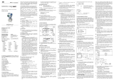
OK-Taste
Bargraph
▼-Taste ▲-Taste
Display
A
bb. 4 Bedienfolie
Menüliste
1 ANZEIGE Anzei
g
eparamete
r
1.1 Pmax Maximaldruckanzeige (High Pressure)
Es wird der Maximaldruck, der während der Messun
g
an
g
ele
g
en hat, in der Anzei
g
e dar
g
estellt.
1.2 Pmin Minimaldruckanzeige (Low Pressure)
Es wird der Minimaldruck, der während der Messun
g
an
g
ele
g
en hat, in der Anzei
g
e dar
g
estellt.
1.3 Tmax Maximaltemperaturanzeige (High Temperature)
Es wird die Maximaltemperatur, die während der Messun
g
an
g
ele
g
en hat, in der Anzei
g
e dar
g
estellt.
1.4 Tmin Minimaltemperaturanzeige (Low Temperature)
Es wird die Minimaltemperatur, die während der Messun
g
an
g
ele
g
en hat, in der Anzei
g
e dar
g
estellt.
1.5 LOESCHEN Löschen der Werte 1.1-1.4
(
Pma
x
, Pmin, Tma
x
, Tmin
)
1.6 INFO Konfiguration der Anzeige
Zuordnung der einstellbaren Ziffern:
"1": 1. Zeile: gemessener Druck 2. Zeile: eingestellte Druckeinheit
"2": 1. Zeile: Ausgangssignal 2. Zeile: mA
"3": 1. Zeile: gemessene Temperatur 2. Zeile: °C
"4": 1. Zeile: gemessener Druck 2. Zeile: Wechsel zwischen Druckeinheit / Ausgangssignal in mA
"5": 1. Zeile: gemessener Druck 2. Zeile: Wechsel zwischen Druckeinheit / Temperatur in °C"
"6": 1. Zeile:
g
emessener Druck 2. Zeile: Wechsel zwischen Druckeinheit / Aus
g
an
g
ssi
g
nal in mA / Temperatur in °C
1.7 RETURN Zurück zum Menü 1 ANZEIGE
2 KALIB Konfi
g
uration von Messbereich, Anzei
g
e und Aus
g
an
g
ssi
g
nal
2.1 NULLPKT Nullierung der Anzeige
Bei Auswahl des Untermenüpunktes mit der OK-Taste erscheint im Display die Anzeige „CONFIRM“. Durch Drücken der OK-Taste für mindestens 2 Sekunden erfolgt die Nullierung und im
Displa
y
erlischt die Anzei
g
e „CONFIRM“.
2.2 KAL REF Justierun
g
des Analo
g
aus
g
an
g
s mit Druckreferenz
2.2.1 NULLPKT Justierung des Anfangswertes für das Ausgangssignal
Nach Anlegen und Übernahme des Referenzdrucks wird bei der Auswahl des Untermenüpunktes mit der OK-Taste im Display die Anzeige „CONFIRM“ erscheinen. Durch Drücken der OK-
Taste für mindestens 2 Sekunden erfolgt die Festlegung des anliegenden Drucks als Anfangswert für das Ausgangssignal (4 mA) und im Display erlischt die Anzeige „CONFIRM“. Der
an
g
ezei
g
te Wert bleibt unverändert.
2.2.2 ENDWERT Justierung des Endwertes für das Ausgangssignal
Nach Anlegen und Übernahme des Referenzdrucks wird bei der Auswahl des Untermenüpunktes mit der OK-Taste im Display die Anzeige „CONFIRM“ erscheinen. Durch Drücken der OK-
Taste für mindestens 2 Sekunden erfolgt die Festlegung des anliegenden Drucks als Endwert für das Ausgangssignal (20 mA) und im Display erlischt die Anzeige „CONFIRM“. Der
an
g
ezei
g
te Wert bleibt unverändert.
2.2.3 RETURN Zurück zum Menü 2.2 KAL REF
2.3 JUSTAGE Einstellun
g
von Messbereich und Nullpunkt
2.3.1 NULLPKT Einstellung des Anfangswertes des Messbereichs
Mit der Taste ▲ und ▼ können Sie einen Anfangswert des Messbereichs definieren. Der zulässige Eingabebereich beträgt 0 … 90% des Original-Messbereichs (Turn Down max. 1:10). Bei
Erreichen des ein
g
e
g
ebenen Wertes werden 4 mA aus
g
e
g
eben.
2.3.2 ENDWERT Einstellung des Endwertes des Messbereichs
Mit der Taste ▲ und ▼ können Sie einen Endwert des Messbereichs definieren. Der zulässige Eingabebereich beträgt 10 … 100% des Original-Messbereichs (Turn Down max. 1:10). Bei
Erreichen des ein
g
e
g
ebenen Wertes werden 20 mA aus
g
e
g
eben.
2.3.3 Z-KORR
Nullpunktkorrektur von Anzeige und Ausgangssignal
Bei Auswahl des Untermenüpunktes mit der OK-Taste erscheint im Display die Anzeige „CONFIRM“. Durch Drücken der OK-Taste für mindestens 2 Sekunden erfolgt die Festlegung des
anlie
g
enden Drucks als Anfan
g
swert für das Aus
g
an
g
ssi
g
nal
(
4 mA
)
und die Nullierun
g
der Anzei
g
e. Im Displa
y
erlischt die Anzei
g
e „CONFIRM“.
2.3.4 RETURN Zurück zum Menü 2.2 KAL REF
2.4 RETURN Zurück zum Menü 2 KALIB
3 SIGNAL Si
g
nalparamete
r
3.1 FUNKTION Funktionsauswahl
„Linear“
„2SQR“ √
2SQR3POW“ √ cut off 2 %
2SQR5POW“ √
3.2 DICHTE Eingabe der Dichte
einstellbarer Bereich: 100 … 9999 k
g
/m3 Die Umrechnun
g
ist nur
g
ülti
g
für die Einheiten [mFH], [cmFH] und [mmFH].
3.3 FILTER Konfiguration der Dämpfung
einstellbarer Bereich: 0 … 100 s
3.4 SIMULAT Simulation des Ausgangssignals
einstellbarer Bereich: beliebi
g
, zum Beispiel: 3,7 … 22 mA
3.5 RETURN Zurück zum Menü 3 SIGNAL
4 EINSTELL Grundeinstellun
g
en
4.1 ANZEIGE Konfi
g
uration der Anzei
g
eeinheit
4.1.1 EINHEIT P Konfiguration der Einheit für Druck
Einheiten: bar, mbar, g/cm², kg/cm², Pa, kPa, Torr, atm, mH2O, ftH2O, MPa, mFH*, cmFH*, mmFH*, mmH2O, mmHg, psi
Die Umrechnun
g
aller druckbezo
g
enen Parameter erfol
g
t automatisch. *Ein
g
abe der Dichte erforderlich.
(
siehe 3.2
)
4.1.2 EINHEIT T Konfiguration der Einheit für Temperatur
Einheiten: °C und °F
4.1.3 RETURN Zurück zum Menü 4.1 ANZEIGE
4.2 HART-ID HART-ID (nur bei HART
®
- Geräten im Multidrop-Modus einzustellen)
Stellen Sie die gewünschte ID-Nr. ein (zwischen "0" und "15") und bestätigen Sie diese mit der OK-Taste. Eine Konfiguration dieser Nummer ist nur erforderlich, wenn Sie das Gerät im
Multidrop-Modus (Verbindung mehrerer HART®-Geräte) betreiben möchten. Ist die ID-Nr. auf "0" eingestellt, so ist der Multidrop-Modus deaktiviert und der Messumformer arbeitet im
analo
g
en Modus.
4.3 USER-L Konfiguration der Sicherheitsebene für den Anwender
Aus Sicherheitsgründen ist es erforderlich vor der Konfiguration der Sicherheitsebene das Passwort einzugeben. Bestätigen Sie dieses mit der OK-Taste. Werksseitig ist das Passwort auf
"0000" eingestellt.
Sicherheitsebenen:
"0": komplettes Menüsystem ist freigegeben
"1": folgende Menüpunkte sind freigegeben: 1 Anzeige, 3 Signal, 4.3 USER-L
"2": fol
g
ende Menüpunkte sind frei
g
e
g
eben: 1 Anzei
g
e, 4.3 USER-L
4.4 PASSWORT Konfiguration des Passworts
Aus Sicherheitsgründen ist es erforderlich vor der Konfiguration das bisherige Passwort einzugeben. Bestätigen Sie dieses mit der OK-Taste. Werksseitig ist das Passwort auf "0000"
eingestellt. Stellen Sie anschließend das neue Passwort ein und bestätigen Sie dieses mit der OK-Taste.
Sollten Sie Ihr Passwort ver
g
essen haben kann von BD SENSORS das Masterpasswort, das bei der Herstellun
g
fest implementiert wurde, an
g
efordert werden.
4.5 SPRACHE Auswahl der Bedienersprachen DE oder EN
4.6 WPROTECT Schreibschutz (HART
®
-Konfiguration)
Einstellun
g
YES: Schreibschutz ist aktiviert, Übertra
g
un
g
der HART®-Befehle zum Speicherort nicht mö
g
lich. Einstellun
g
NO: Schreibschutz ist deaktiviert.
4.7 RETURN Zurück zum Menü 4 EINSTELL
5 SERVICE Service
5.1 WERKSEIN Werkseinstellun
g
en zurücksetzen
5.2 FEHLER-I Definition des Fehlerstroms
einstellbare Werte: 21,6 mA oder 3,8 mA; der
g
ewählte Fehlerstrom wird bei einer Störun
g
der Elektronik aus
g
e
g
eben
5.3 TYPE Anzei
g
e des Gerätet
y
ps
5.4 SER-NR Anzei
g
e der ein
g
estellten Seriennumme
r
5.5 VERS Anzei
g
e der Pro
g
rammversion
(
Firmware
)
5.6 RETURN Zurück zum Menü 5 SERVICE
6 RETURN Zurück zum Anzei
g
emodus

BD-Sensors-Str.1; 95199 Thierstein, Germany
Tel.: +49 (0) 92 35 / 98 11 0 | www.bdsensors.com
© 2019 BD|SENSORS GmbH –
All rights reserved
Supplementary sheet to operating manual for
x|act ci, xIact i, XMP ci, XMP i, XMD
Only use in combination with the product
specific operating manual!
Operation
Display and operating module
DANGER
for IS version
Danger of death from explosion
- Explosion hazard when device is
opened in an explosive atmosphere
- Do not open or configure the device
while an explosion hazard exists!
Fig. 3 touch pad
The indication of the measured value as well as the configuration
of the individual parameters occurs through a menu via the
display. The individual functions can be set with the help of three
miniature push buttons located under the metal cap. Furthermore,
a bargraph is shown in the display, indicating the current pressure
input as percentage of the specified pressure range.
The menu system is a closed system allowing you to scroll both
forward and backward through the individual set-up menus to
navigate to the desired setting item. All settings are permanently
stored in a Flash EPROM and therefore available again even
after disconnecting from the supply voltage.
!
Pay attention that no moisture can enter the device during
configuration. Moreover, the seals and the sealing surfaces
should not get dirty, as this may cause a reduction of the
degree of protection depending on the case of application or
place of installation. This can lead to a breakdown of the
device or to irreparable damages on the device. Right after
configuration, the metal cap has to be screwed on again, by
hand.
Structure of the menu system
-
▲-button: with this button you move forward in the menu
system or increase the displayed value; it will
also lead you to the operating mode (beginning
with menu item "1 DISPLAY")
-
▼-button: with this button you move back in the menu
system or decrease the displayed value; it will
also lead you to the operating mode (beginning
with menu item "5 SERVICE")
-
OK-button: with this button menu items and set values
have to be confirmed
execution of configuration:
- set the desired menu item by pushing the ▲- or ▼-button
- activate the set menu item by pushing the OK-button
- set the desired value or select one of the offered settings by
using the ▲- or ▼-button
- store/confirm the set value/selected setting and exit the
menu by pushing the OK-button
If a parameter is configurable by a value, each digit may be
configured separately. That means after activating such a
menu item (e. g. "2.3.1 OFFSET") by pushing the OK-
button, the first digit of the currently set value will start to
blink. Now scroll up or down to the desired digit via the ▼-
or ▲-button and confirm it with the OK-button. After that, the
next digit will start to blink. Configure it in the same way. In
the menu items "2.3.1 OFFSET" and "2.3.2 FINALVAL", the
decimal point will then start to blink and it is also possible to
change its position by using the ▼- or ▲-button. By
confirming the position with the OK-button, the total value
will be stored if permissible. If the value is out of range, an
error message (e. g. Error 03) will appear in the display and
the set value will not be stored.
If you intend to set a negative value, the first digit has to be
configured with the ▼-button.
Error messages
PASSED PARAMETER
TOO SMALL
entered parameter value is too
small
PASSED PARAMETER
TOO LARGE
entered parameter value is too
large
LOOP CURRENT NOT
ACTIVE
loop current is not active (HART
ID > 0, device works in Multidrop
mode)
APPLIED PROCESS
TOO LOW applied process is too low
APPLIED PROCESS
TOO HIGH applied process is too high
LOWER RANGE
V
ALUE TOO HIGH
lower range value (OFFSET) is
too high
LOWER RANGE
V
ALUE TOO LOW
lower range value (OFFSET) is
too low
UPPER RANGE VALUE
TOO HIGH
upper range value (FINALVAL) is
too high
UPPER RANGE
V
ALUE TOO LOW
upper range value (FINALVAL) is
too low
SPAN TOO SMALL span too small
DEVICE MALFUNCT internal failure please send the
device to BD SENSORS for repair
Structure of the menu system
OK-button
bargraph
▼-button ▲-button
display
Menu list
1 DIPLAY Displa
y
paramete
r
1.1 Pmax Maximum pressure display (high pressure)
The maximum pressure that occurred durin
g
the measurement is shown on the displa
y
.
1.2 Pmin Minimum pressure display (low pressure)
The minimum pressure that occurred durin
g
the measurement is shown on the displa
y
.
1.3 Tmax Maximum temperature display (high temperature)
The maximum temperature that occurred durin
g
the measurement is shown on the displa
y
.
1.4 Tmin Minimum temperature display (low temperature)
The minimum temperature that occurred durin
g
the measurement is shown on the displa
y
.
1.5 CLEAR Delete the values 1.1-1.4
(
Pma
x
, Pmin, Tma
x
, Tmin
)
1.6 INFO Configuration of the display
Assignment of the settable digits
"1": 1st line: measured pressure 2nd set pressure unit
"2": 1st line: Output signal 2nd line: mA
"3": 1st line: measured temperature 2nd line: °C
"4": 1st line: measured pressure 2nd line: Change between pressure unit / output signal in mA
"5": 1st line: measured pressure 2nd line: Change between pressure unit / temperature in °C"
"6": 1st line: measured pressure 2nd line: Chan
g
e between pressure unit / output si
g
nal in mA / temperature in °C
1.7 RETURN Return to menu 1 DISPLAY
2 CALIB Confi
g
uration of measurin
g
ran
g
e, displa
y
and output si
g
nal
2.1 ZERO Zeroing the display
The message “CONFIRM” appears on the display when selecting the subsidiary menu item with the OK button. By holding the OK button pressed for at least 2 seconds the zeroing is
performed, and the messa
g
e “CONFIRM” disappears from the displa
y
.
2.2 CAL REF Ad
j
usts the analo
g
ue output with pressure reference
2.2.1 OFFSET Adjusts the starting value for the output signal
After the reference pressure has been applied and accepted, selecting the subsidiary menu item with the OK button causes the message "CONFIRM" to appear on the display. By holding the
OK button pressed for at least 2 seconds the applied pressure is specified as the starting value for the output signal (4 mA), and the message "CONFIRM" disappears from the display. The
displa
y
ed value remains unchan
g
ed.
2.2.2 FINALVAL Adjusts the end value for the output signal
After the reference pressure has been applied and accepted, selecting the subsidiary menu item with the OK button causes the message "CONFIRM" to appear on the display. By holding the
OK button pressed for at least 2 seconds the applied pressure is specified as the end value for the output signal (20 mA), and the message "CONFIRM" disappears from the display. The
displa
y
ed value remains unchan
g
ed.
2.2.3 RETURN Return to menu 2.2 CAL REF
2.3 ADJUST Sets the measurin
g
ran
g
e and the zero point
2.3.1 OFFSET Sets the starting value of the measuring range
The ▲ and ▼ buttons allow you to define a starting value for the measuring range. The permitted input range is between 0 … 90% of the original measuring range (turn down max. 1:10). 4
mA is output when the value that has been entered is reached.
2.3.2 FINALVAL Sets the end value of the measuring range
The ▲ and ▼ buttons allow you to define an end value for the measuring range. The permitted input range is between 10 … 100% of the original measuring range (turn down max. 1:10). 20
mA is output when the value that has been entered is reached.
2.3.3 Z-CORR Zero-point correction of the display and output signal
The message "CONFIRM" appears on the display when selecting the subsidiary menu item with the OK button. By holding the OK button pressed for at least 2 seconds the applied pressure
is specified as the startin
g
value for the output si
g
nal
(
4 mA
)
, and the displa
y
is zeroed. The messa
g
e "CONFIRM" disappears from the displa
y
.
2.3.4 RETURN Return to menu 2.2 CAL REF
2.4 RETURN Return to menu 2 CALIB
3 SIGNAL Si
g
nal parameters
3.1 FUNKTION Function selection
"LINEAR" (linear function)
“2SQR” √
“2SQR3POW” ³ cut off 2 %
“2SQR5POW” ⁵
3.2 DENSITY Input of the density
settable ran
g
e: 100 … 9999 k
g
/m3 Conversion is onl
y
applicable to the units [mFH], [cmFH] and [mmFH].
3.3 DAMP Configuration of the damping
settable ran
g
e: 0 … 100 s
3.4 SIMULAT Simulation of the output signal
settable ran
g
e: an
y
, for example: 3.7 ... 22 mA
3.5 RETURN Return to menu 3 SIGNAL
4 SETTINGS Basic settin
g
s
4.1 DISPLAY Confi
g
uration of the displa
y
unit
4.1.1 UNIT P Configuration of the unit for pressure
Units: bar, mbar, g/cm², kg/cm², Pa, kPa, Torr, atm, mH2O, ftH2O, MPa, mFH*, cmFH*, mmFH*, mmH2O, mmHg, psi
The conversion of all pressure-related parameters is performed automaticall
y
. *Input of the densit
y
is required.
(
see 3.2
)
4.1.2 UNIT T Configuration of the unit for temperature
Units: °C and °F
4.1.3 RETURN Return to menu 4.1 DISPLAY
4.2 HART-ID HART-ID (only to be set with HART
®
devices in multi-drop mode)
Set the desired ID no. (between "0" and "15") and confirm this with the OK button. It is only necessary to configure this number if you want to operate the device in multi-drop mode
(
connection of a number of HART® devices
)
. If the ID no. is set to "0", the multi-drop mode is deactivated, and the measurement transducer operates in analo
g
ue mode.
4.3 USER-L Configuration of the user's security level
For security reasons it is necessary to enter the password before configuring the security level. Confirm this with the OK button. The password is factory-set to "0000".
Security levels:
"0": the whole menu system is enabled
"1": the following menu items are enabled: 1 Display, 3 Signal, 4.3 USER-L
"2": the followin
g
menu items are enabled: 1 Displa
y
, 4.3 USER-L
4.4 PASSWORD Configuration of the password
For security reasons it is necessary to enter the previous password before configuration. Confirm this with the OK button. The password is factory-set to "0000". Then set the new password
and confirm this with the OK button.
If
y
ou have for
g
otten
y
our password,
y
ou can request the master password, which is fixed at manufacture, from BD SENSORS.
4.5 LANGUAGE Selection of DE or EN as the user lan
g
ua
g
e
4.6 WPROTECT Write protection (HART
®
-configuration)
Settin
g
YES: write protection is activated, transmission of the HART® commands to the stora
g
e location is not possible. Settin
g
NO: write protection is deactivated.
4.7 RETURN Return to menu 4 SETTINGS
5 SERVICE Service
5.1 FACTORY Reset to factor
y
settin
g
s
5.2 ERR CURR Definition of the current
settable values: 21.6 mA or 3.8 mA; the selected error current is output in response to a malfunction in the electronics
5.3 TYPE Displa
y
of the device t
y
pe
5.4 SER-NO Displa
y
of the set serial numbe
r
5.5 VERS Displa
y
of the pro
g
ram version
(
firmware
)
5.6 RETURN Return to menu 5 SERVICE
6 RETURN Return to displa
y
mode
/