Page is loading ...

Whole House Salt-Free Water Treatment System
Whole House Salt-Free Water Treatment System WH-WS-SF
Owner’s Manual
1. Read all instructions carefully before operation.
2. This system is not intended for treating water that is microbiologically unsafe or of
unknown quality without adequate disinfection before or after the system.
Tier1 Technical Support:
1-855-378-9116

2
Table of Contents
What’s Included ..............................................................................3
Operating Conditions .....................................................................4
Installation Guidelines.....................................................................5
Assembly Instructions .....................................................................6
Troubleshooting and Replacements Parts .........................................8
Salt-Free System
Sediment
TIER1_WH_WS_SF_844
TIER1_WH_WS_SF_1054

3
UNPACKING/INSPECTION
Check the entire unit for any shipping-related damage, missing parts, or damage to shipping cartons.
Small parts needed to assemble the system are contained in a parts box. To avoid loss of small parts,
keep them in the parts box until you are ready to use them.
Inlet/Outlet adapters (3)
Two 3/4", One 1"
Prefilter bracket, wrench, screws
Adapter (cap) (1)
Prefiltration System
Flex Connectors (2)
Stainless Steel Nipple (2)
Plastic Nipple (1)
Tank pre-filled with media (1)
Locking Clips (2)
Ball Valve
Zippered Neoprene
Tank Cover
(Optional Upgrade)

4
OPERATING CONDITIONS
SPECIFICATIONS
Please review operating pressures, temperatures, and water chemistry limitations to ensure compatibility.
Salt-Free System
System Specifications 854 1054
Service Flow Rate 12 gpm 15 gpm
Filter Media Volume
- Cubic Feet .11 ft .18 ft
Filter Tank Size 8” x 44” 10” x 54”
Media Type Template Assisted Crystallization
Media Preloaded Yes
Water Temperature 41-100 degrees F
Max Water Pressure 125 psi
Plumbing Connections 3/4” straight adaptors
Electrical Requirements None
Hardness Max 75 gpg
Ferrous Iron Max 0.3 mg/L
Manganese Max 0.05 mg/L
Copper Max 1.3 mg/l
pH level 6.5 to 8.5
Hydrogen Sulfide MUST be removed upstream.
Do not install any filters after the salt-free tank, or before any devices for which scale prevention is
required. Point of use filters, e.g. carbon or Reverse Osmosis, are exempt from this requirement. Do not
apply phosphate or any other anti-scalant either before or after the salt-free tank.
TOOLS, PIPE AND FITTINGS AND OTHER MATERIALS
Our systems are complete, self-contained, loaded with media and ready to use. Inlet and outlet fittings
are included with the filter. To maintain full valve flow, 3/4” or 1” pipes to and from the filter fittings are
recommended. You should maintain the same, or larger pipe size as the water supply pipe, up to the
inlet and outlet. Use copper, brass, or PEX pipe and fittings. Some codes may also allow PVC plastic pipe.
Helpful Tools: screwdriver, Teflon tape, adjustable wrenches, razor knife
To avoid pinched o-rings during installation, apply NSF certified lubricant to all seals.
Additional tools may be required if modification into home plumbing is required.
Note: the 1054 series tank can support a flow rate
up to 20 gpm but is limited by the prefilter to 15
gpm. Use of the prefilter is strongly recommended
to help extend the life and efficacy of the salt free
system media.

5
4
A
B
Models A B
48"8"
58"10"
SSYYSSTTEEMMDDIIMMEENNSSIIOONNSS
8000
10000
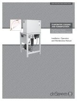
SYSTEM DIMENSIONS
INSTALLATION GUIDELINES
SAFETY GUIDE
For your safety the information in this manual must be followed to minimize the risk of electric shock,
property damage, or personal injury.
Check and comply with your state and local codes. You must follow these guidelines.
Use care when handling the filter tank. Do not turn upside down, drop, drag, or set on sharp
protrusions.
PROPER INSTALLATION
This system must be properly installed and located in accordance with the installation instructions
before it is used.
Use only lead-free solder and flux for all sweat-solder connections, as required by state and federal
codes. Maximum allowable inlet water pressure is 125 psi. If daytime pressure is over 80 psi, night time
pressure may exceed the maximum. If necessary, use a pressure reducing valve to reduce the flow.
WARNING: Pre-filter must be installed level with tank head, as shown in below diagram.
Discard all unused parts and packaging material after installation. Small parts remaining after the
installation could be a choking hazard.
Models A B
844 48” 8”
1054 58” 10”
Note: Because this system is designed to be an
upflow system, the water flow direction through
the media tank will be opposite the arrows on
the tank cap.

6
1. If your hot water tank is electric, turn off the power to it to avoid damage to the tank’s element.
2. If you have a private well, turn off the power to the pump, then shut off the main water valve. If you
have municipal water, shut off the main valve. Turn on a cold water faucet,(preferably on the lowest
floor of the house) until all pressure is relieved and the water flow stops.
3. ON COPPER PLUMBING SYSTEMS BE SURE TO INSTALL A GROUNDING WIRE BETWEEN THE INLET
AND OUTLET PIPING TO MAINTAIN GROUNDING.
4. Solder joints near the adapter must be done before connecting piping to the adapter. Always leave at
least 6” (152 mm) between the adapter and joints when soldering pipes connected to the valve.
Failure to do so could damage the valve.
5. Attach the pre-filtration system to wall at height equal with tank adapter. Make sure you have the
appropriate amount of space needed before attaching to walls/pipes.
6. Thread steel nipples into inlet and outlet on pre-filter housing cap.
7. Lubricate tank cap adapter o-rings with NSF certified lubricant and insert into inlet/outlets of tank
caps. Insert red locking clips to lock in adapters. Note the water flow should be opposite of the
direction indicated by arrows on caps.
8. Attach flex connectors to tank cap adaptors. Do not apply tape as they include a sealing washer.
9. Install system ball valve/shut-off valve prior to prefilter. Close ball valve.
10. Connect the ball valve, prefilter and tank together with the flex connectors. Make sure not to over
tighten any plastic parts, and do not over bend the flex connectors.
11. Slowly turn on the main water supply. Check any new plumbing for leaks.
12. Slowly turn the ball valve, allowing water to flow through the system, watching for leaks.
13. Remove the aerator screen from the nearest faucet, and run water at this faucet for at least 10
minutes until system is free of any air or foreign material resulting from the plumbing work.
14. If provided, cover tanks with zip-on neoprene sleeves.
15. Your system is now ready for use.
INSTALLATION
WHERE TO INSTALL
Place the filter tank as close as possible to the pressure tank (well system) or water meter (city water).
Connect the filter to the main water supply pipe BEFORE the water heater.
DO NOT RUN HOT WATER THROUGH THE FILTER. Temperature of water passing through the filter must
be less than 100° F. Keep the filter out of direct sunlight as its heat may soften and distort plastic parts.
Do not install the filter in a place where it could freeze as water freezing may damage the system. Install
the filter in a place water damage is least likely to occur if a leak develops. The manufacturer will not
repair or pay for water damage.
If installing in an outside location, you must take the steps necessary to ensure the filter, installation
plumbing, wiring, etc., are as well protected from the elements, contamination, vandalism, etc., as when
installed indoors.
INSTALLATION INSTRUCTIONS

7
INSTALLATION
IMPORTANT: IRON AND MANGANESE IN YOUR WATER
Iron and Manganese
Just as with conventional water softening media, the salt-free (scaleless) media needs to be protected
from excess levels of certain metals that can easily coat the active surface, reducing its effectiveness over
time. Public water supplies rarely present a problem, but if the water supply is from a private well you
should confirm that the levels of iron (Fe) and manganese (Mn) are less than 0.3 mg/L and 0.05 mg/L
respectively. Copper should be less than 1.3 mg/L.
Copper
Copper usually originates from new copper plumbing installed upstream of the salt-free system. If this
condition exists, we recommend waiting 3-4 weeks before placing the system in operation. This will allow
the copper surfaces to be fully flushed and to develop a natural protective surface. To further minimize
any problem with excess copper, plumbers are advised to avoid applying excess flux on the inner surfaces
of the pipe and to use a low-corrosivity water soluble flux listed under the ASTM B813 standard. Once
the plumbing connections are complete, place the salt-free system in bypass prior to following the
startup procedure, and flush the plumbing for at least 10 minutes.
Things to watch for during the first 30-90 days:
Faucet aerators and drains may plug occasionally as old scale is removed from your plumbing system and
water heater. You may also see milky water while the descaling is taking place. This is because the salt-
free system media is removing old scale deposits from your pipes.
INSTALLER NOTES RE: SALT-FREE SYSTEM
The salt-free, or scaleless, system differs from a conventional softener or media filter in a number of key
respects. The system is light and only partially filled with media - please note this is normal. The Up-Flow
operation of the system requires a lot of freeboard to allow the bed to fully fluidize. The system has no
underbed, so you can tip the system over without any fear of upsetting the media. This makes
transportation and installation much easier than conventional systems. Because the scaleless system
operates in the Up-Flow mode, the tank connections are opposite of the indicator arrows on the
caps. Please see the “important note about iron, manganese and copper” above. To retain the attractive
appearance of your new water filter, clean occasionally with mild soap solution. Do not use abrasive
cleaners, ammonia, or solvents. Never subject your system to freezing or to temperatures above 100° F.
SALT-FREE SYSTEM GOOD PRACTICES
If your dishwasher is severely coated with scale at the time of installation, we recommend that you
purchase a product like Jet-Dry Dishwasher cleaner to accelerate the cleaning. After this initial cleaning
the salt-free system media should keep it clean. We also recommend that you drain your water heater
tank. This should be done 30 to 60 days after the salt-free system is installed, and again in one year.
This is a good practice that can dramatically increase the life of your water heating appliance.
If you have an electric “tank type” water heater, for optimum results and higher efficiency, we
recommend you change the heating elements to a “low watt density” model. Please insure that
the watt density is specified at less than 70 watts per square inch, and is compatible with the
brand you own. If you can only change one heating element, change the lower unit which
operates most of the time. The salt-free water system media will help keep the tank and
heating elements free of scale and operating at peak efficiency.

8
TROUBLESHOOTING
ISSUES
ISSUE POTENTIAL CAUSE SOLUTION
Filter bleeds taste and odor or
sediment
Bypass valve open Close bypass valve
Defective or stripped media bed. Replace Media
Quality of water has changed. Analyze water sample
to determine change.
Filter capacity too small Replace with larger unit or add
another
Leak between valve and central
tube
Check if central tube is
cracked or o-ring is damaged.
Replace faulty parts.
Low water pressure Iron or scale build-up in line
feeding unit.
Clean pipes
TIER1_WH_WS_SF_844/1054 05.11.22
For questions about your Tier1 whole home water system product
installation or performance troubleshooting, please call Tier1 Technical
Support at 1-855-378-9116 Monday - Friday, 8 am - 5 pm central time or
send an email to support@tier1water.com.
www.tier1water.com
REPLACING THE MEDIA BED
Under normal operating conditions the effective life of the salt-free system media will be several years,
depending upon water quality and usage. After this time, scaling problems may return. When this
happens, contact Tier1 for a replacement media bed. www.tier1water.com.
REPLACING THE SEDIMENT PRE-FILTER
The sediment filter in the pre-filter housing should be replaced every six months or sooner as necessary.
Filter specs: 20” x 4.5” spun polypropylene 5 micron sediment filter. We recommend replacing your O-
ring with each filter change. Sediment filter replacement is available at www.tier1water.com.
Part number: TIER1-P5-20BB
QUESTIONS?
/