tekmar 400 Installation guide

Category
Thermostats
Type
Installation guide

This manual is also suitable for

tekmarNet
®
2 House Control 400
D 400
05/16
HVAC Systems
Replaces: 09/13
Installation & Operation Manual
© 2016 400_D - 05/16
1 of 32
Menu
House Control 400
Item
VIEW
Boil Exp Boil System
Zones
1 2 3 4
Calls
Pumps
Benefits
Energy efficiency through Outdoor Temperature
Reset with Indoor Feedback
Indoor Feedback minimizes the water temperature
(increasing energy savings), and the efficiency of
your mechanical equipment through integrated
tekmarNet
®
Thermostats
Zone Synchronization reduces equipment cycling
Auto Differential - Reduces boiler cycling
Compact enclosure for flexible installation
Simple zone expansion using Wiring Centers
The tN2 House Control 400 is designed to operate all
of the mechanical equipment in a residential hydronic
heating system, coordinating their operation with network
communication. It can be used in applications ranging
from a single zone of baseboard with an on/off boiler, to
multiple radiant floor zones with a modulating/condensing
boiler. This control regulates one space heating water
temperature through Outdoor Temperature Reset and
Indoor Temperature Feedback. It is capable of controlling
a single on/off, two stage, or modulating boiler, Domestic
Hot Water, setpoint loads, 4 on-board zone valves, and
can expand up to 24 zones in total.
Features
Automatic Boiler Differential
Boiler Protection
DHW Post Purge
DHW Priority (optional)
DHW control
Exercising
For use with tekmarNet
®
2 thermostats ONLY
Four 24 V (ac) powered zone outputs
Indoor Temperature Feedback
One touch overrides (with optional User Switch)
Only requires 2 Wires Per Zone
Outdoor Temperature Reset
Powered pump outputs
Setpoint operation
Single on/off, two stage, or modulating boiler
control
System Setback (with optional Timer)
Warm Weather Shut Down
Zone Synchronization
tN4 expansion terminals
Introduction
© 2016 400_D - 05/16
2 of 32
Table of Contents
Installation ......................................................................3
Preparation ................................................................ 3
Physical Dimensions ................................................. 3
Installation Location .................................................. 4
Rough-In Wiring ........................................................ 4
Sizing the Transformer .............................................. 4
Control Wiring ........................................................... 4
Sensor Wiring ............................................................ 7
Testing the Sensor Wiring ......................................... 9
Testing the Control Wiring ......................................... 9
Max Heat ..................................................................10
Applications .................................................................. 11
User Interface ...............................................................13
Display......................................................................13
Symbols ...................................................................13
Navigating The Display ............................................14
Access Levels and Thermostat Lock ........................14
Programming and Settings .......................................14
View Menu ...............................................................15
Adjust Menu ........................................................16-18
Monitor Menu ...........................................................19
Toolbox Menu .......................................................... 20
Sequence of Operation ................................................ 21
tekmarNet
®
System ..................................................21
Boiler Temperature Reset Operation ........................21
Domestic Hot Water Tank Operation ....................... 22
Setpoint Operation ...................................................24
Boiler Operation .......................................................24
Pump Operation ...................................................... 26
Energy Saving Features ...........................................27
Troubleshooting ............................................................28
Error Messages ....................................................... 29
Frequently Asked Questions ................................... 30
Job Record ...............................................................31
Technical Data ..............................................................32
Limited Warranty and Product Return Procedure ........32
To avoid serious personal injury and damage to the equipment:
It is the installers responsibility to ensure that this
control is safely installed according to all applicable
codes and standards.
Improper installation and operation of this control could
result in damage to the equipment and possibly even
personal injury or death.
This electronic control is not intended for use as a
primary limit control. Other controls that are intended
and certified as safety limits must be placed into the
control circuit.
Do not attempt to service the control. There are no user
serviceable parts inside the control. Attempting to do
so voids warranty.
Important Safety Information
It is your responsibility to ensure that this control is safely installed according to all applicable codes and standards.
tekmar is not responsible for damages resulting from improper installation and/or maintenance.
Read Manual and all product labels
BEFORE using the equipment. Do
not use unless you know the safe and
proper operation of this equipment.
Keep this Manual available for easy
access by all users.
Replacement Manuals are available at
tekmarControls.com
Disconnect all power before opening
the control.
© 2016 400_D - 05/16
3 of 32
Getting Started
Congratulations on the purchase of your new tekmarNet
®
House Control!
This manual covers the complete installation, programming and sequence of operation for this control. You will also find
instruction on testing, commissioning, and troubleshooting the control and system that it operates.
Installation
The installer must ensure that this control and its wiring are
isolated and/or shielded from strong sources of electromagnetic
noise. Conversely, this Class B digital apparatus complies
with Part 15 of the FCC Rules and meets all requirements of
the Canadian Interference-Causing Equipment Regulations.
However, if this control does cause harmful interference
to radio or television reception, which is determined by
turning the control off and on, the user is encouraged to try
to correct the interference by re-orientating or relocating
the receiving antenna, relocating the receiver with respect
to this control, and/or connecting the control to a different
circuit from that to which the receiver is connected.
Cet appareil numérique de la classe B respecte toutes
les exigences du Règlement sur le matériel brouilleur du
Canada.
Radio Frequency Interference
Preparation
Tools Required
---------------------------------------------------------------------------------------
tekmar or jeweler screwdriver
Phillips head screwdriver
Needle-nose Pliers
Wire Stripper
Materials Required
-----------------------------------------------------------------------------------
(2) #10 x 1" Wood Screws
(4) Wire Nuts
18 AWG LVT Solid Wire (Low Voltage Connections)
14 AWG Solid Wire (Line Voltage Connections)
tekmar 009K (24 V (ac) transformer with 4" x 4" junction box)
Cable or Conduit Connectors
Power Required
--------------------------------------------------------------------------------------
120 V (ac), 1-phase, 15 A service from circuit breaker
panel
Power disconnect (optional)
Physical Dimensions
Menu
House Control 400
Item
R
+
ComBoil Out
VlvC VlvC VlvC
Zone 3Zone 1 Zone 2 Zone 4
Made in Canada
VlvC
Zone 1
H8005A
Zone 2 Zone 3 Zone 4
tN2tN2 tN2tN2 tN2tN2 tN2tN2
Sensors - No Power
Call Call
CtN4 C
Input Power
Boiler Mod (dc) Boil Exp.
Setpoint DHW
Use at least 167°F
(75°C) conductors
Front View Side View Back View
5–1/2"
(140 mm)
5–1/2"
(140 mm)
1–1/8" (30 mm)
7/8"
(22 mm)
CL
1/2" Knock-out (x 4)
Control designed to mount on 4" x 4" electrical
box (not included). Electrical box shown
comes with tekmar 009K
Strip wires 1/2 inch
(13 mm). Installed
wires are not removable.
12-18 AWG
DHW Pump
Pump Power L
400
Boil System Pump
Ø 1/8"
(3 mm)
7/8” x 1/2" (23 mm x 12 mm)
Knock-out (x 4)
1/2" x 5/8"
(12 mm x 16 mm)
Knock-out (x 4)
2–1/4"
(57 mm)
4–1/2" (114 mm)
© 2016 400_D - 05/16
4 of 32
The control requires an external transformer. A tekmar
Transformer 009 (or 009K which includes a 4”x 4” electrical
box) can supply up to 40 VA, and includes an in-line fuse
to protect the transformer and control.
In order to correctly size the external transformer, all loads
connected to the control must be taken into account.
When adding up the loads, consider the following:
tekmarNet
®
2 Thermostats draw approximately 2 VA each.
Each zone valve must be sized for peak load. This can
be obtained by multiplying the peak current draw (in
Amps) by 24 V (ac).
The total power capacity of the power supply should be
larger than the total load of all the devices connected
to the control. This total load must not exceed 100 VA.
Multiple tekmar Transformer 009’s can be wired together
to increase total VA capacity.
Sizing the Transformer
Each cable must be pulled from the equipment to the
control’s plastic enclosure. All low voltage wiring connections
enter the enclosure through conduit knockouts on the
sides, or through the square knockouts on the rear. It is
recommended to label each cable for easy identification.
All low voltage wires are to be stripped to a length of 3/8”
(9 mm) to ensure proper connection to the control.
Pull two conductor 18 AWG LVT cable, up to 500 feet
(150 m) for the following equipment:
tekmarNet
®
2 Thermostats
Zone Valves
Boiler Stage 1 T-T
Boiler Stage 2 T-T (if applicable)
Modulating Boiler 0-10 V (dc) or 4-20 mA (if applicable)
Outdoor Temperature Sensor
Boiler Supply Temperature Sensor
DHW Tank Temperature Sensor (if applicable)
DHW Tank Aquastat (if applicable)
Setpoint Device (if applicable)
Pull three conductor 18 AWG LVT cable for the following
equipment:
tekmarNet
®
4 Accessories (User Switch, Timer, and
Wiring Center)
Low Voltage Wiring
-----------------------------------------------------------------------------------
Rough-In Wiring
Line Voltage Wiring
-----------------------------------------------------------------------------------
The control operates a number of pumps through wiring
on the back of the control. The control must be mounted
to a 4" x 4" electrical junction box so that these electrical
connections are safely contained.
For ease of service, the circuit breaker or power disconnect
should be located in reasonably close proximity to the
equipment.
All line voltage wire connections are recommended to
be pulled inside a flexible or solid conduit. Always follow
proper wiring practices, building and electrical codes for
your jurisdiction.
Each cable must be pulled from the equipment to the
electrical junction box. It is recommended to label each
cable for easy identification. All line voltage wires should
be stripped to a length of 1/2" (13 mm).
Pull a three conductor 14 AWG cable for the following
equipment:
Circuit Breaker or Power Disconnect
Boiler System Pump
DHW Tank Pump (if applicable)
Installation Location
When choosing the location for the control, consider the
following:
Keep dry. Avoid potential leakage onto the control.
RH 90% to 104°F (40°C).
Non-condensing environment.
Do not expose to operating temperatures beyond 32-
104°F (0-40°C)
Provide adequate ventilation.
Keep away from equipment, appliances or other
sources of electrical interference.
Locate the control near pumps and/or zone valves if
possible.
Provide easy access for wiring, viewing and adjusting
the control.
Mount approximately 5 ft. (1.5 m) off the finished floor.
Install the electrical junction box to a wall using #10
x 1” wood screws. Wall anchors are recommended
when mounting to sheet rock wallboard or masonry.
© 2016 400_D - 05/16
5 of 32
Zone
1 2 3 4
Thermostat Load
Zone Valve Load
Floating
Action (VA)
Control
Load (VA)
Total Zone Load
+ + + + +
2
Transformer
must exceed:
VA
Control Wiring
Line Voltage Wiring
-----------------------------------------------------------------------------------
Ground the Pumps
Connect the pump grounds to the power supply
ground as shown in Figure 1. The ground wire must
also be grounded to the electrical box.
CAUTION: TURN ALL POWER OFF BEFORE PERFORMING ANY WIRING.
Pump
Leads
DHW Pum
p
Boil System Pump
Power Source
(L,N)
Pump
Pump
Figure 1 - Connect
Ground Wires
DHW Pum
p
Boil System Pump
Power Source
(L,N)
Pump
Pump
Figure 2 - Connect
Neutral Wires
Strip wires 1/2 inch
(13 mm). Installed
wires are not removable.
12-18 AWG
DHW Pump
Pump Power L
400
Boil System Pump
DHW Pump
Boil System Pump
Power
Source
(L,N)
Figure 3 - Connect
Line Voltage (Hot)
Strip wires 1/2 inch
(13 mm). Installed
wires are not removable.
12-18 AWG
DHW Pump
Pump Power L
400
Boil System Pump
DHW Pump
Power
Source
(L,N)
Boil System Pump
Figure 4 - Connect
Pump Line (Hot)
Wire the Pump Neutrals
Connect the Neutral (N) wires from each pump and wire
to the 115 V (ac) Neutral (N) wire. If the transformer has
been mounted to this electrical box, connect its neutral
wire with this group. This is shown in Figure 2.
Wire the Pump Power (L)
Connect the 115 V (ac) line voltage (L) wire to the red
Pump Power (L) wire on the back of the House Control
and to the 115 V (ac) side of the transformer. Use a
wire nut or approved connector. See Figure 3.
Wire the Pumps
Wire each remaining line voltage pump wire into the
push-in wire connector of the corresponding pump
lead on the back of the House Control. This is shown
in Figure 4.
The following chart is provided to simplify transformer sizing:
© 2016 400_D - 05/16
6 of 32
External Power Supply
It is strongly recommended that a transformer with an in-line
fuse be used in order to protect the transformer from high
currents. The tekmar Transformer 009 includes a fuse.
Connect the 24 V (ac) leads from the transformer to the
C and R terminals marked “Input Power” on the 400.
tN2 Thermostats
The 400 is designed to operate with tekmarNet
®
2 Thermostats.
They provide the heating and cooling control for each zone,
and communicate with any other tekmarNet
®
device on
the system.
Connect the tN2 terminals from each thermostat to the
corresponding tN2 terminals for each zone on the 400.
Zone Valves
Wire the zone valves to the C and Vlv terminals on the
400.
End switches on zone valves are not required when
using the 400.
tN4 Boiler Expansion Terminals
The 400 uses the Boiler Expansion tN4 and C terminals to
communicate with additional thermostats, setpoint controls,
and other tekmarNet
®
devices.
Connect the tN4 and C Boil Exp. terminals on the 400
to the corresponding tN4 and C Expansion terminals
of the additional external device.
Low Voltage Wiring
-----------------------------------------------------------------------------------
Ensure that the pump wires are neatly tucked inside
the electrical box.
Using 2 of the 4 holes in the back of the enclosure, se-
curely fasten it to the electrical junction box with 2 #10
screws as shown in Figure 5.
Install The Enclosure
---------------------------------------------------------------------------------
Figure 5
Domestic Hot Water (DHW) or Setpoint Call
When the control receives a DHW Call or Setpoint Call for
heat it will override Outdoor Reset and Indoor Feedback
and operate the boiler to heat the DHW tank or the Setpoint
equipment.
To create a DHW call, wire a dry contact OR apply
24 V (ac) to the DHW call terminals.
To create a Setpoint call, wire a dry contact OR apply
24 V (ac) to the Setpoint call terminals.
Wiring the Boiler
The 400 can operate a single modulating boiler, single
on-off, or a single two-stage on-off boiler.
On/Off Boiler
Connect the Boiler Stage 1 terminals on the 400 to the
T-T (or R-W) terminals on the boiler.
If required, connect the Boiler Stage 2 terminals on the
400 to the second stage T-T (or R-W) terminals on the
boiler.
Modulating Boiler
Wire the Mod (dc/mA) positive (+) and negative (-) ter-
minals on the 400 to the input signal terminals on the
boiler. Correct polarity of the wires is important.
In some cases, the modulating boiler also requires
contact closure on the T-T terminals to fire the boiler. If
required, connect the Boiler Stage 1 terminals on the
400 to the T-T (or R-W) terminals on the boiler.
R
C
L
N
Expansion
tN4 Boil
CtN4
Modulating
Boiler
—+
2
1
Menu
House Control 400
Item
+
ComBoil Out DHW
VlvC VlvC VlvC
Zone 3Zone 1 Zone 2 Zone 4
VlvC
Com
Zone 1 Zone 2 Zone 3 Zone 4
tN2 tN2 tN2 tN2 tN2tN2 tN2tN2
Sensors - No Power
Call Call
tN4 C
Mod dc/mA Boil Exp.
Setpoint DHW
RC
Input Power
H8005B
Made in Canada
Use at least 167°F
(75°C) conductors
Stage 2Stage 1
115 V (ac)
L
N
G
Boil
DHW
to pump grounds
N
L
Boil System Pump
DHW Pump
Pump Power L
Strip wires
1/2 inch (13 mm).
Installed wires are
not removable.
12-18 AWG
(red)
(black)
(black)
Rear Line Voltage Wiring Diagram
--------------------------------------------------------------------
© 2016 400_D - 05/16
7 of 32
Front Low Voltage Wiring Diagram
-------------------------------------------------------------------
Sensor Wiring
The 070 can be mounted directly onto a wall with the
wiring entering through the back or bottom of the en-
closure. Do not mount the 070 with the conduit knock-
out facing upwards as rain could enter the enclosure
and damage the sensor.
In order to prevent heat transmitted through the wall
from affecting the sensor reading, it may be necessary
to install an insulating barrier behind the enclosure.
The 070 should be mounted on a wall which best rep-
resents the heat load on the building (a northern wall
for most buildings and a southern facing wall for build-
ings with large south facing glass areas). The 070
should not be exposed to heat sources such as venti-
lation or window openings.
The 070 should be installed at an elevation above the
ground that will prevent accidental damage or tampering.
Mounting the Outdoor Sensor 070
--------------------------------------------------------------------
R
C
L
N
Expansion
tN4 Boil
CtN4
Modulating
Boiler
—+
2
1
Menu
House Control 400
Item
+
ComBoil Out DHW
VlvC VlvC VlvC
Zone 3Zone 1 Zone 2 Zone 4
VlvC
Com
Zone 1 Zone 2 Zone 3 Zone 4
tN2 tN2 tN2 tN2 tN2tN2 tN2tN2
Sensors - No Power
CallCall
tN4 C
Mod dc/mA Boil Exp.
Setpoint DHW
RC
Input Power
H8005B
Made in Canada
Use at least 167°F
(75°C) conductors
Stage 2Stage 1
115 V (ac)
L
N
G
Boil
DHW
to pump grounds
N
L
Boil System Pump
DHW Pump
Pump Power L
Strip wires
1/2 inch (13 mm).
Installed wires are
not removable.
12-18 AWG
(red)
(black)
(black)
Zone Valves
24 V (ac) Transformer 009
DHW Call
from DHW Tank
Aquastat (optional)
Setpoint Call
Outdoor
Sensor
070
Boiler Supply
Sensor 082
DHW Tank Sensor 082
One or Two Stage
Boiler T-T
tekmarNet
®
2 Thermostats
tekmarNet
®
4
Expansion to
Wiring Centers,
Timers, or
User Switch
Remove
cover by
sliding
upwards
away from
the base.
To wire from
the back,
remove the
knock-out in
the sensor
base.
S1
S1
If using
conduit,
remove
the flexible
plug from
the base
bottom.
S1
S1
Attach the
base to
the wall,
soffit or
electrical
box.
S1
S1
© 2016 400_D - 05/16
8 of 32
Connect 18 AWG or similar wire to the two terminals
provided in the enclosure and run the wires from the
070 to the control. Do not run the wires parallel to tele-
phone or power cables. If the sensor wires are located
in an area with strong sources of electromagnetic in-
terference (EMI), shielded cable or twisted pair should
be used or the wires can be run in a grounded metal
conduit. If using shielded cable, the shield wire should
be connected to the Com or Com Sen terminal on the
control and not to earth ground.
Follow the sensor testing instructions in this brochure
and connect the wires to the control.
Replace the cover of the sensor enclosure.
Wiring the Outdoor Sensor 070
-----------------------------------------------------------------------
Mounting the Boiler Sensor 082
----------------------------------------------------------------------
Note: These sensors are designed to mount on a pipe or
in a temperature immersion well.
The Universal Sensor should be placed downstream of a
pump or after an elbow or similar fitting. This is especially
important if large diameter pipes are used as the thermal
stratification within the pipe can result in erroneous sensor
readings. Proper sensor location requires that the fluid is
thoroughly mixed within the pipe before it reaches the sensor.
Strapped to Pipe
The Universal Sensor can be strapped directly to the pipe
using the cable tie provided. Insulation should be placed
around the sensor to reduce the effect of air currents on
the sensor measurement.
Immersion Well
If a Universal Sensor is mounted onto 1(25 mm) diameter
L type copper pipe, there is approximately an 8 second
delay between a sudden change in water temperature and
the time the sensor measures the temperature change.
This delay increases considerably when mild steel (black
iron) pipe is used. In general, it is recommended that
a temperature well be used for steel pipe of diameter
greater than 1-1/4(32 mm). Temperature wells are also
recommended when large diameter pipes are used and
fluid stratification is present.
Conduit Connection
The Universal Sensor 082 and Universal Sensor Enclosure
080 (sold separately) are specifically designed to mount
onto a 3/8” (10 mm) ID temperature well that is supplied
with an end groove. To install the well, plumb a ‘T’ into the
pipe and fix the well into the ‘T. The 080 enclosure has
a 7/8” (22 mm) back knockout that must be removed and
fitted over the temperature well. The 082 is then inserted
into the well and the retaining clip supplied with the
enclosure is snapped onto the well end groove. If the well
has a threaded end, the installer must supply a standard
threaded conduit retaining ring. The two wires from the
sensor are connected to the terminal block provided in the
enclosure. The other side of the terminal block is used to
connect wires from the control.
Bottom of
Enclosure 080
Universal
Sensor 082
Cable Tie
Sensor Well
Retaining Clip
Universal
Sensor 082
Wires from
outdoor sensor
and sensor
common
terminals on
tekmar control
Sensor is built into
the enclosure
S1
S1
Slide cover
back over
base
© 2016 400_D - 05/16
9 of 32
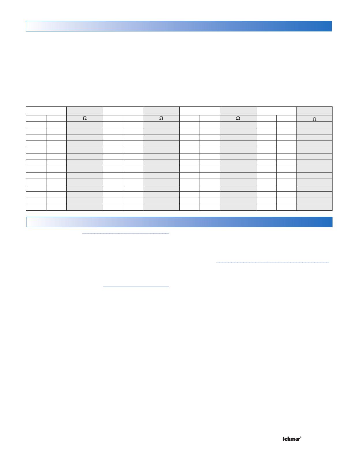
A good quality test meter capable of measuring up to 5,000
k(1 k= 1000 ) is required to measure the sensor
resistance. In addition to this, the actual temperature must be
measured with either a good quality digital thermometer, or if a
thermometer is not available, a second sensor can be placed
alongside the one to be tested and the readings compared.
First measure the temperature using the thermometer and
then measure the resistance of the sensor at the control.
The wires from the sensor must not be connected to the
control while the test is performed. Using the chart below,
estimate the temperature measured by the sensor. The
sensor and thermometer readings should be close. If the
test meter reads a very high resistance, there may be a
broken wire, a poor wiring connection or a defective sensor.
If the resistance is very low, the wiring may be shorted,
there may be moisture in the sensor or the sensor may
be defective. To test for a defective sensor, measure the
resistance directly at the sensor location.
Do not apply voltage to a sensor at any time as damage
to the sensor may result.
Testing the Sensor Wiring
Temperature Resistance Temperature Resistance Temperature Resistance Temperature Resistance
°F °C
°F °C °F °C °F °C
-50 -46 490,813 20 -7 46,218 90 32 7, 33 4 160 71 1,689
-45 -43 405,710 25 -4 39,913 95 35 6,532 165 74 1,538
-40 -40 336,606 30 -1 34,558 100 38 5,828 170 77 1,403
-35 -37 280,279 35 2 29,996 105 41 5,210 175 79 1,281
-30 -34 234,196 40 4 26,099 110 43 4,665 180 82 1,172
-25 -32 196,358 45 7 22,763 115 46 4,184 185 85 1,073
-20 -29 165,180 50 10 19,900 120 49 3,760 190 88 983
-15 -26 139,400 55 13 17, 43 6 125 52 3,383 195 91 903
-10 -23 118,018 60 16 15,311 130 54 3,050 200 93 829
-5 -21 100,221 65 18 13,474 135 57 2,754 205 96 763
0 -18 85,362 70 21 11,883 140 60 2,490 210 99 703
5 -15 72,918 75 24 10,501 145 63 2,255 215 102 648
10 -12 62,465 80 27 9,299 150 66 2,045 220 104 598
15 -9 53,658 85 29 8,250 155 68 1,857 225 107 553
Testing the Control Wiring
Testing the Power
-----------------------------
If the control display does not turn on, check the Input
Power wiring terminals using an electrical multimeter. The
voltage should measure between 21.6 to 26.4 V (ac). If the
voltage is below this range, measure the line voltage side
of the transformer. The voltage should measure between
103.5 to 126.5 V (ac).
Testing the Thermostats
----------------------
If the thermostat display turns on, this indicates that the
thermostat is operating correctly and there are no electrical
issues. In the event that the display is off, or the display is
cycling on and off, follow this procedure.
1. Remove the tN2 wires from the thermostat.
2. Use an electrical meter to measure DC voltage between
the tN2 terminals.
If the DC voltage is 0 V (dc) for 20 seconds, then there is
an open or short circuit in the tN2 wires. If the DC voltage
is 0 V (dc) for 10 seconds and then is 23 to 24 V (dc) for 5
seconds, this indicates the wiring is correct.
3. Connect the thermostat to the tN2 wires from a zone
on a House Control, Wiring Center, or Zone Manager.
4. If the thermostat display is off, or is cycling on and off,
move the thermostat to the next available zone on the
House Control, Wiring Center, or Zone Manager.
If the thermostat display remains permanently on, there
may be a fault with the previously tried zone on the House
Control, Wiring Center, or Zone Manager.
If the thermostat display continues to be off, or is cycling
on and off, there may be a fault on the thermostat.
If a fault is suspected, contact your tekmar sales
representative for assistance.
User Test
--------------------------------------
The User Test is found in the Toolbox menu of the control.
Press the Menu button to access the Toolbox Menu. Press
the Item button to locate the User Test.
Start the test sequence by going to the User Test item and
pressing the ‘Up’ arrow button.
Pause the test sequence by pressing the Item button. To
advance to the next step, press the Item button again.
If the test sequence is paused for more than five minutes,
the control exits the entire test routine and returns to normal
operation.
To advance to a particular step, repeatedly press and
release the Item button to display the appropriate device.
User Test Sequence
Step 1
Zone 1 turns on for 10 seconds.
Step 2
Zone 2 turns on for 10 seconds.
Step 3
Zone 3 turns on for 10 seconds.
Step 4
Zone 4 turns on for 10 seconds.
Step 5
The DHW pump turns on for 10 seconds.
Step 6
The boiler system pump turns on for 10
seconds.
Step 7
During the boiler test step, zone relays 1 through
4 turn on, and the boil system pump turns on.
© 2016 400_D - 05/16
10 of 32
If the Boil Type is 1 Stage, the boiler stage 1 relay is
closed for 10 seconds and then opened.
If the Boil Type is 2 Stage, the boiler stage 1 relay is
closed for 10 seconds, then the boiler stage 2 relay is
closed for 10 seconds and then both relays are opened.
If Boiler Type is modulating 0 - 10, the boiler stage
1 relay is closed for 10 seconds and the modulating
output operates at 50 % [5 V (dc)].
If Boiler Type is modulating 4 - 20, the boiler stage
1 relay is closed for 10 seconds and the modulating
output operates at 50 % (12 mA).
Step 8
Control returns to normal operation.
Testing the Zone Output
----------------------
Activate the User Test sequence and pause at Step 1 by
pressing the Item button once Zone 1 turns on. Using an
electrical meter, measure the voltage between the zone
valve and the common (C) terminals. The voltage should
measure between 21.6 V (ac) and 26.4 V (ac). Repeat for
Zones 2, 3, and 4.
Testing the DHW Pump
Activate the User Test sequence and pause at Step 5 by
pressing the Item button once the DHW pump turns on.
Using an electrical meter, measure the voltage between
the DHW pump and a neutral. The voltage should measure
between 103.5 V (ac) and 126.5 V (ac).
Testing the Boiler System Pump
---------------
Activate the User Test sequence and pause at Step 6 by
pressing the Item button once the boiler system pump turns
on. Using an electrical meter, measure the voltage between
the boiler system pump and a neutral. The voltage should
measure between 103.5 V (ac) and 126.5 V (ac).
Testing the Boiler Stage 1 Contact
-------------
Activate the User Test sequence and pause at Step 7 by
pressing the Item button once the boiler stage 1 turns on.
Using an electrical meter, measure for continuity over the
boiler stage 1 terminals.
Testing the Boiler Stage 2 Contact
-------------
This test applies for 2 stage on-off boilers only.
Activate the User Test sequence and pause at Step 7 by
pressing the Item button once the boiler stage 2 turns on.
Using an electrical meter, measure for continuity over the
boiler stage 2 terminals.
Testing the Boiler Modulating Output
----------
This test applies for modulating boilers only.
Active the User Test sequence and pause at Step 7 by
pressing the Item button once the boiler stage 1 turns on.
Using an electrical meter, measure for either a 5 V (dc) or
12 mA signal. The Boil Type setting selects whether the
signal is V (dc) or mA.
Testing the DHW Call
--------------------------
Remove all wires from the DHW Call terminals. The control
display should show no DHW Call. Reconnect wires. Then
apply either a short circuit or 24 V (ac) over the DHW Call
terminals. The control should now show a DHW Call.
Testing the Setpoint Call
----------------------
Remove all wires from the Setpoint Call terminals. The
control display should show no Setpoint Call. Reconnect
wires. Then apply either a short circuit or 24 V (ac) over
the Setpoint Call terminals. The control should now show
a Setpoint Call.
The control has a function called Max Heat. In this mode,
the control turns on and operates the system up to the
maximum set temperatures as long as there is a call for
heat. Use this mode to run the circulators during system
start-up and commissioning, purging air from the piping.
This function is useful when drying sheet rock and paint
in the building.
To enable Max Heat, enter the Toolbox Menu and find Max
Heat. Use the up arrow to select ‘On.
When a space heating call is present, the boiler will
run to maintain a target of Boil Design + 10°F (+ 6°C).
(One can purge the system using this test and leave
the boiler un-powered. This will prevent heat from en-
tering the system during the purge.)
When a DHW Call or Setpoint Call is present, the
boiler will operate at the DHW exchange or Setpoint
temperature settings.
WWSD and DHW Priority is disabled during Max Heat
mode.
When Max Heat is on the display will show ‘Max Heat
Test’.
Max Heat will automatically turn off after 24 hours.
To Cancel Max Heat, go to Max Heat in the Toolbox menu
and use the down arrow to select ‘Off.
Max Heat
© 2016 400_D - 05/16
11 of 32
Applications
115 V (ac)
L
N
G
Boil Sys
DHW
(P1)
(P2)
to pump grounds
N
L
Boil System Pump
DHW Pump
Pump Power L
Strip wires
1/2 inch (13 mm).
Installed wires are
not removable.
12-18 AWG
Expansion
tN4 Boil
CtN4
1
R
C
L
N
(red)
(black)
(black)
Menu
House Control 400
Item
+
ComBoil Out DHW
VlvC VlvC VlvC
Zone 3Zone 1 Zone 2 Zone 4
VlvC
Com
Zone 1 Zone 2 Zone 3 Zone 4
tN2 tN2 tN2 tN2 tN2 tN2 tN2 tN2
Sensors - No Power
Call Call
tN4 C
Mod dc/mA Boil Exp.
Setpoint DHW
RC
Input Power
H8005B
Made in Canada
Use at least 167°F
(75°C) conductors
Stage 2Stage 1
Description: The House Control 400 operates an On/Off boiler with indirect Domestic Hot Water. The boiler is operated
using Outdoor Reset with Indoor Feedback, which supplies the lowest comfortable water temperature to four onboard
hydronic zones. Additional boiler temperature zones can be added using the tN4 Expansion terminals.
Single Boiler, DHW Tank, 4 Boiler Zones A400-1
400
070
S2
S1
Outdoor
Sensor
(S2)
tekmarNet
®
2 Thermostats
Boiler T-T
24 V (ac)
Transformer 009
Boiler Sensor (S1)
DHW Call
Zone Valves (Z1 to Z4)
tekmarNet
®
4
Expansion to
Wiring Centers,
Timers, or
User Switch
tekmarNet
®
2 Thermostats
P1
P2
Z1 Z2 Z3 Z4
© 2016 400_D - 05/16
12 of 32
Description: The House Control 400 operates a modulating boiler with indirect Domestic Hot Water. The House Control
400 operates using Outdoor Reset and Indoor Feedback, which supplies the lowest water temperature to eight hydronic
zones. The four extra zones are connected to the Wiring Center 313 using the tN4 Boiler Expansion terminals.
115 V (ac)
L
N
G
Boil Sys
DHW
(P1)
(P2)
to pump grounds
N
L
Boil System Pump
DHW Pump
Pump Power L
Strip wires
1/2 inch (13 mm).
Installed wires are
not removable.
12-18 AWG
Expansion
tN4 Boil
CtN4
Modulating
Boiler
—+
1
R
C
L
N
313
(red)
(black)
(black)
Menu
House Control 400
Item
+
ComBoil Out DHW
VlvC VlvC VlvC
Zone 3Zone 1 Zone 2 Zone 4
VlvC
Com
Zone 1 Zone 2 Zone 3 Zone 4
tN2 tN2 tN2 tN2 tN2tN2 tN2 tN2
Sensors - No Power
Call Call
tN4 C
Mod dc/mA Boil Exp.
Setpoint DHW
RC
Input Power
H8005B
Made in Canada
Use at least 167°F
(75°C) conductors
Stage 2Stage 1
400
070
313
Single Boiler, DHW, 8 Boiler Zones A400-2
S2
S1
S3
24 V (ac)
Transformer 009
Zone Valves (Z1 to Z4)
DHW Sensor (S3)
Boiler Sensor (S1)
tekmarNet
®
2 Thermostats
Outdoor
Sensor
(S2)
tekmarNet
®
4
Expansion to
Wiring Centers,
Timers, or
User Switch
tekmarNet
®
2 ThermostatstekmarNet
®
2 Thermostats
(if applicable)
P1
P2
Z1 Z2 Z3 Z4
© 2016 400_D - 05/16
13 of 32
Calls
CALLS
Displays any call for heat the control is
receiving.
Pumps
PUMPS
Displays any pump currently operating.
Zones
1 2 3 4
ZONES
Displays if an on-board zone is operating.
WARNING
Displays if an error exists on the system.
Saving
ENERGY SAVING INDICATOR
Displays when the system is saving energy.
See Energy Saving Features section.
WWSD
WWSD
Displays when the system is in Warm
Weather Shut Down.
°F°C
minhr
sec%
°F, °C, %, HOURS, MINUTES, SECOND
Units of measurement for current number.
UNOCCUPIED
Indicates that a User Switch or Timer has
put the system into UnOccupied.
BOILER
Indicates that the boiler should be
heating.
MAXMIN
MIN / MAX
Displays when an operating temperature
reaches a minimum or maximum value.
Symbols
Display
MONITOR
VIEW
ADJUST
MAXMIN
Boil Exp
DHW Setp
Boil System
Zones
DHW Var1 2 3 4
1 2
AM
min
sec
hr
PM
Calls
Pumps WWSD Saving
Item Field
Displays the name
of the selected item
Number Field
Displays the
current value of
the selected item
Status Fields
Displays the current
status of the control’s
inputs, outputs and
operation. Most symbols
in the status field are
only visible when the
VIEW Menu is selected
Menu Field
Displays the
current menu
User Interface
© 2016 400_D - 05/16
14 of 32
Navigating The Display
Menu Button
-----------------------------------------------------------------------------------------
The 400 uses a simple user interface to accomplish a
variety of functions. The four buttons beneath the display
are used to change the menu, sort through Items, and
adjust each setting as required.
The menus display in the Menu Field at the top left side of
the LCD. Four menus are available: View, Adjust, Monitor
and Toolbox (identified by the wrench symbol).
The View menu allows the user to view the current
status of various system parameters.
The Adjust menu allows the installer to adjust settings
to ensure control operation matches requirements of
the mechanical system.
The Monitor menu keeps track of run times and
other important data that is collected during system
operation.
The Toolbox menu is a source of system information
and includes useful tools for commissioning and test-
ing the system.
Item Button
------------------------------------------------------------------------------------------
Each menu contains a list of Items that can be viewed and,
in some cases, adjusted. Press the item button to scroll
through the list in each Menu.
To view the next available item, press and release the
Item button.
To view the previous item, hold down the Item button,
and press and release the Up button.
Up and Down Buttons
--------------------------------------------------------------------------------
The Up and Down buttons are primarily used for adjusting
settings.
To adjust a setting:
Select the appropriate menu using the Menu button.
Select the item using the Item button.
Use the Up or Down button to make the adjustment.
Default Item
------------------------------------------------------------------------------------------
When navigating menus, the display reverts back to the
default item (View Menu) after 60 seconds of button
inactivity.
To set the default item in the View menu, display the
item for more than five seconds.
Access Levels and Thermostat Lock
The 400 is shipped pre-programmed with common settings.
The 400 has an ‘Installer access level that allows full access
to all settings and a ‘Useraccess level that restricts the
number of settings to only the Warm Weather Shut Down
and the temperature units. The 400 defaults to the ‘User
access level after 12 hours of operation.
All thermostats are locked while the 400 is in the ‘User’
access level. Certain settings on the thermostat will be
unavailable while the thermostat is locked.
To change to the ‘Installer’ access level and Unlock the
thermostats:
In the Toolbox menu, locate Access
Adjust the access level to ‘Installer’ by pressing the up
or down button. This will permit setting changes to the
control.
Programming and Settings
The 400 settings can be found in the Adjust’ menu. When
changing the items value, the setting is saved to the control’s
memory once the Item button is pressed to advance to the
next item, or after 60 seconds, the control times out and
reverts back to the ‘View’ menu.
All settings are stored in permanent memory and will be
kept correctly during any loss of power.
© 2016 400_D - 05/16
15 of 32
Item Field Range Description
VIEW
Zones
Calls
Pumps
-76 to 149°F
(-60.0 to 65.0°C)
OUTDOOR SECTION B
Current outdoor air temperature as measured by the outdoor sensor. The
outdoor air temperature is shared to all thermostats in the tekmarNet
®
system.
VIEW
Zones
Calls
Pumps
-22 to 266°F
(-30.0 to 130.0°C)
BOILER SUPPLY SECTION B
Current boiler supply water temperature as measured by the boiler
sensor. The control operates the boiler so that the boiler supply is
within the boiler differential of the boiler target. ‘MIN’ is shown when
the control is providing boiler minimum protection to the boiler.
VIEW
Zones
Calls
Pumps
– – –, 35 to 200°F
(1.5 to 93.0°C)
BOILER TARGET SECTION B
The boiler target is the temperature the control is currently trying to
maintain at the boiler supply sensor. The boiler target is calculated based
on the outdoor design, boiler design, and boiler minimum settings.
is displayed when no heat is required for boiler zones. ‘MIN’ is shown
when the control is providing boiler minimum protection to the boiler.
VIEW
Zones
Calls
Pumps
0-100%
BOILER MODULATION SECTION E
Current percent modulation of the boiler’s burner. The boiler modulation
increases when the boiler supply is less than the boiler target. The
boiler modulation decreases when the boiler supply is greater than the
boiler target.
Note: This item is only available when the Boil Type setting is set to
0-10 or 4-20.
-22 to 266°F
(-30.0 to 130.0°C)
DHW TANK SECTION C
Current Domestic Hot Water tank temperature as measured by the optional
DHW sensor. If the DHW tank temperature falls 6°F (3.0°C) below the
DHW Occ setting, a DHW call is created and the tank is heated.
Note: This item is only available when a DHW sensor is installed and
DHW Mode is set from 1 to 4.
-22 to 266°F
(-30.0 to 130.0°C)
DHW SUPPLY SECTION C
Current supply water temperature to the indirect DHW tank heat
exchanger as measured by the DHW sensor.
Note: This item is only available when a DHW sensor is installed and
DHW Mode is set to 5.
--
SYSTEM IN AWAY SECTION G
The heating system is in the Away scene. The DHW tank will not be
heated. Setpoint calls are still responded to.
Use the User Switch to change scene out of Away.
VIEW MENU
View Menu (1 of 1)
The View menu items display the current operating temperatures and status information
of the system.
After the last item, the control returns to the first item in the menu.
© 2016 400_D - 05/16
16 of 32
Item Field Range
Access
Description Set to
ADJUST
-60 to 45°F
(-51.0 to 7.0°C)
Default = 10°F
(-12.0°C)
Installer
OUTDOOR DESIGN SECTION B
Typically set to the temperature of the coldest day
of the year. The outdoor air temperature used in the
boiler heating curve that is used to determine the boiler
target temperature.
EMS2,
EMS1,
4-20
0-10,
2STG,
1STG
Default = 1STG
Installer
BOILER TYPE SECTION E
The type of boiler connected to the control.
1STG = single one-stage on-off boiler
2STG = single two-stage on-off boiler
0-10 = 0-10 V (dc) modulating boiler
4-20 = 4-20 mA modulating boiler
EMS1 = tekmar boiler staging controls
EMS2 = Viessmann modulating boilers with
OpenTherm
70 to 200°F
(21.0 to 93.5°C)
Default = 180
°F
(82.0°C)
Installer
BOILER DESIGN SECTION B
The supply water temperature required for the boiler
zones to heat the building on the typical coldest day
of the year. Recommendations:
High mass radiant floor = 120°F (50°C)
Low mass radiant floor = 140°F (60°C)
Fancoil or air handling unit = 190°F (90°C)
Copper fin-tube convector = 180°F (80°C)
Radiators = 160°F (70°C)
Low profile baseboard = 150°F (65°C)
OFF, 80 to 180°F
(26.5 to 82.0°C)
Default = 140
°F
(60.0°C)
Installer
BOILER MINIMUM SECTION B
The minimum allowed boiler target temperature.
Recommendations:
Condensing gas or electric boiler = OFF
Non-condensing gas and oil boilers = 140°F (60°C)
Note: If Boiler Type is 0-10 V (dc), 4-20 mA, EMS1
or EMS2, this setting is defaulted to Off.
ADJUST
sec
10 to 230 seconds
Default = 30
seconds
Installer
BOILER MOTOR SECTION E
The time required for the modulating actuating motor
to fully open the gas valve or ramp the burner fan
from off to full speed on a modulating boiler. Set to
30 seconds unless otherwise recommended by the
boiler manufacturer.
Note: This item is only available when the Boiler
Type is 0-10 V (dc) or 4-20 mA.
ADJUST MENU
Adjust Menu (1 of 3)
The Adjust menu items are the programmable settings used to operate
the mechanical equipment.
Continued on next page.
© 2016 400_D - 05/16
17 of 32
Item Field Range
Access
Description Set to
ADJUST
0 to 50%
Default = 0%
Installer
MINIMUM MODULATION SECTION E
The minimum percent modulation of the boiler
burner.
Note: This item is only available when the Boiler
Type is 0-10 V (dc) or 4-20 mA.
ADJUST
sec
0 to 3:00 minutes
Default = 10
seconds
Installer
MODULATION DELAY SECTION E
Delay time between the burner firing and the boiler
releasing to modulation.
Note: This item is only available when the Boiler
Type is 0-10 V (dc) or 4-20 mA.
ADJUST
40 to 100°F
(4.5 to 38.0°C)
Default = 70
°F
(21.0°C)
Installer
User
WWSD OCCUPIED SECTION G
The system’s Warm Weather Shut Down temperature
during Occupied periods or when a schedule is not
used.
ADJUST
40 to 100°F
(4.5 to 38.0°C)
Default = 60
°F
(15.5°C)
Installer
WWSD UNOCCUPIED SECTION G
The systems Warm Weather Shut Down temperature
during Unoccupied periods.
Note: Item is only available when a schedule or User
Switch is present on the system.
Off, 1, 2, 3, 4, 5
Default = 2
Installer
DHW MODE SECTION C
Selects the DHW mode of operation. The
mode determines the zone and boiler system
pumps operation whenever the DHW pump is in
operation.
100 to 200°F
(38.0 to 93.5°C)
Default = 180
°F
(82°C)
Installer
DHW EXCHANGE SECTION C
Selects the minimum boiler target to the DHW heat
exchanger.
Note: Item is only available in DHW Modes 1 through 4
when a DHW sensor is not connected. It is available in
DHW Mode 5 when a DHW sensor is connected.
70 to 180°F
(21.0 to 82.0°C)
Default = 125
°F
(51.5°C)
Installer
DHW OCCUPIED SECTION C
Selects the temperature of the indirect DHW tank.
Note: Item is only available when an optional DHW
sensor is installed except in DHW Mode 5.
ADJUST
Off or On
Default = On
Installer
DHW UNOCCUPIED SECTION G
Selects whether or not the indirect DHW tank should
be heated to during Unoccupied time periods.
Note: Item is only available when Schedule #1
is available or a User Switch is present on the
system.
Adjust Menu (2 of 3)
ADJUST MENU
Continued on next page.
© 2016 400_D - 05/16
18 of 32
Item Field Range
Access
Description Set to
ADJUST
60 to 200°F
(15.5 to 93.5°C)
Default = 180
°F
(82.0°C)
Installer
SETPOINT SECTION D
The minimum boiler target temperature when a
Setpoint Call is present.
ADJUST
°F or °C
Default =
°F
Installer
User
UNITS
Selects units for temperature display.
Adjust Menu (3 of 3)
ADJUST MENU
After the last item, the control returns to the first item in the menu.
© 2016 400_D - 05/16
19 of 32
Item Field
Range
Description
MONITOR
-76 to 149°F
(-60.0 to 65.0°C)
OUTDOOR HIGH
Records the highest outdoor temperature since the item was
last cleared. Press and hold the Up and Down buttons while
viewing to reset.
MONITOR
-76 to 149°F
(-60.0 to 65.0°C)
OUTDOOR LOW
Records the lowest outdoor temperature since the item was
last cleared. Press and hold the Up and Down buttons while
viewing to reset.
MONITOR
hr
0 to 9999 Hours
Default = 0 hr
RUN TIME (BOILER)
The total ‘on’ time of the boiler relay since the item was last
cleared. Press and hold the Up and Down buttons while
viewing to reset.
MONITOR
hr
DHW
Pumps
0 to 9999 Hours
Default = 0 hr
RUN TIME (DHW PUMP)
The total running time of the DHW Pump since this item was
last cleared. Press and hold the Up and Down buttons while
viewing to reset.
MONITOR
hr
Boil System
Pumps
0 to 9999 Hours
Default = 0 hr
RUN TIME (BOIL SYSTEM PUMP)
The total running time of the Boil System Pump since this item
was last cleared. Press and hold the Up and Down buttons
while viewing to reset.
MONITOR
hr
Saving
0 to 9999 Hours
Default = 0 hr
RUN TIME ($AVING)
Maintains a record of the total length of time the $aving icon
has been active. Press and hold the Up and Down buttons
while viewing to reset.
MONITOR
hr
0 to 9999 Hours
Default = 0 hr
BOILER ENERGY USE
Multiply this value by the BTU rating (input BTU/hr) of the boiler
to get an approximate energy consumption (in BTU’s) for the
boiler. Press and hold the Up and Down buttons while viewing
to reset. Not available when Boiler Type is EMS1 or EMS2.
MONITOR MENU
After the last item, the control returns to the first item in the menu.
The Monitor menu items provide information about the system’s operation and performance.
To clear any item back to default, press and hold the Up and Down buttons while viewing
that item.
Monitor Menu (1 of 1)
© 2016 400_D - 05/16
20 of 32
Item Field
Range
Description
On or Off
Default = Off
USER TEST TESTING
Begins the test routine which tests the main control’s functions.
See the Testing the Control section for more details. Use the
up button to turn the User Test On.
On or Off
Default = Off
MAX HEAT TESTING
When selected, control operates the system up to maximum set
temperatures. Will operate up to 24 hours, or can be manually
turned Off. See Max Heat in the Testing the Control section
for more details.
400
J12 04B
TYPE AND SOFTWARE VERSION
Displays the type number of the product, followed by the current
software version beneath.
INST (Installer)
or USER
Default = INST
ACCESS LEVEL
Selects the Access Level of the control, which determines the
Menu items available. USER provides the most limited level of
access and shows the fewest possible items.
When set to USER, all thermostats are locked and the number
of thermostat settings available are reduced.
OFF, SEL
Default = Off
FACTORY DEFAULTS
Loads the factory default settings. Hold the Up and Down
buttons for 1 second until SEL is shown.
0 to 24 devices
BOIL DEVICES
Displays the number of devices on the Boil bus (Water
Temperature). This is made up of thermostats connected to
the House Control and to the Boil Expansion terminals.
See Troubleshooting
Guide
HISTORY - 1 THROUGH 5
Displays a history of any past errors that have occurred on the
system. Will clear after 30 days, or press Up and Down buttons
for 1 second to manually clear. The last 5 history items will
display if present.
TOOLBOX MENU
After the last item, the control returns to the first item in the menu.
The Toolbox Menu is a location for system information and
Test functions. If any errors are present on the system, they
will be located at the beginning of this menu.
Toolbox Menu (1 of 1)
  • Page 1 1
  • Page 2 2
  • Page 3 3
  • Page 4 4
  • Page 5 5
  • Page 6 6
  • Page 7 7
  • Page 8 8
  • Page 9 9
  • Page 10 10
  • Page 11 11
  • Page 12 12
  • Page 13 13
  • Page 14 14
  • Page 15 15
  • Page 16 16
  • Page 17 17
  • Page 18 18
  • Page 19 19
  • Page 20 20
  • Page 21 21
  • Page 22 22
  • Page 23 23
  • Page 24 24
  • Page 25 25
  • Page 26 26
  • Page 27 27
  • Page 28 28
  • Page 29 29
  • Page 30 30
  • Page 31 31
  • Page 32 32

tekmar 400 Installation guide

Category
Thermostats
Type
Installation guide
This manual is also suitable for

Ask a question and I''ll find the answer in the document

Finding information in a document is now easier with AI