Gossen MetraWatt SINEAX CAM Installation guide

Type
Installation guide

This manual is also suitable for

Installationsanleitung
Instructions d'installation
Installation instructions
SINEAX CAM
157 489 07.15
Camille Bauer Metrawatt AG
Aargauerstrasse 7
CH-5610 Wohlen / Schweiz
Telefon +41 56 618 21 11
Telefax +41 56 618 35 35
E-Mail: info@cbmag.com
http://www.camillebauer.com
Available documentation
Installation instructions
The present document provides instructions about the installation
of the SINEAX CAM with IEC61850 interface. To provide more
detailed information it also refers to some of the below listed
documents, which are available via included CD or via
http://www.camillebauer.com
.
CAM61850.PAR-E.V1.01.110830.PDF User specific parameterization
Describes the possibilities for the application specific
parameterization of the IEC61850 bus card. The possible
settings via Web interface of the bus card and by means of
manufacturer independent configuration tools is shown.
CAM61850.MICS.V1.2.090520.PDF
MICS: Model Implementation Conformance Statement
This specification presents the top-level IEC61850 data model
that has been implemented in the SINEAX CAM. The definitions
of all used Logical Nodes and their components are also
included for completeness.
CAM61850_PICS.V1.3.090520. PDF PICS: Protocol Implementation Conformance Statement
The ACSI conformance statements provide details about the
IEC61850 communication service interface of the SINEAX CAM.
CAM61850.PIXIT.V1.3.090520. PDF PIXIT: Protocol Implementation eXtra Information for Testing
This document specifies the protocol implementation extra
information for testing of the IEC 61850 interface of the SINEAX
CAM.
CAM61850.TICS.V1.1.090520. PDF TISSUES Implementation Conformance Statement
This document provides a template for the tissues conformance
statement. The tissue conformance statement is required to
perform a conformance test and is referenced on the certificate.
SINEAX_CAM-61850_Certificate.pdf
The IEC61850 conformance test certificate for the SINEAX CAM,
issued by KEMA.
PICS, MICS, PIXIT and TISSUES form the basis for the conformance test according to IEC61850-10.
17/25
Tools for the SINEAX CAM installation
Tool Functionality
CB-Manager
Configuration of measurement functionality, averaging times etc.
Configuration of I/O interface
Network settings of IEC61850 bus card
Configuration of IP addresses for the time synchronization via
NTP server
Web-Interface
Import / Export of ICD file
Changing of IED name
Adjusting the measurement thresholds (Dead-band) for the
reporting
Manufacturer
independent
configuration tool
Modifying the ICD file to fit the application
Changing IED name and device instance name
Removing unused node instances
Removing measurement values from node instances
Content
1. Bus connection .................................................................................................................................................. 18
1.1 Connection ................................................................................................................................................ 18
1.2 Network installation by means of the CB-Manager software ............................................................... 18
1.3 Time synchronization via NTP protocol ................................................................................................. 19
2. IEC61850 application ......................................................................................................................................... 19
3. Information about the logical nodes ................................................................................................................ 19
3.1 MMXU ......................................................................................................................................................... 20
3.2 MMXN ......................................................................................................................................................... 20
3.3 MHAI ........................................................................................................................................................... 20
3.4 MHAN.......................................................................................................................................................... 20
3.5 MMTR1, MMTR2 ......................................................................................................................................... 20
3.6 MSTA .......................................................................................................................................................... 20
3.7 MSQI ........................................................................................................................................................... 21
3.8 GGIO1…12 ................................................................................................................................................. 21
4. Measurement data ............................................................................................................................................. 22
4.1 Polling ........................................................................................................................................................ 22
4.2 Unbuffered Reporting ............................................................................................................................... 22
Appendix: Logical node information ................................................................................................................... 23
18/25
1. Bus connection
The configuration of the network settings of the IEC61850 bus card of the SINEAX CAM can be performed
via one of the local interfaces by means of the CB-Manager software only.
1.1 Connection
Before a device can be connected to an existing Ethernet network, you have to ensure that it will not disturb the
normal network service. The rule is:
None of the devices to connect is allowed to have the same IP address than another device
already installed
The factory setting of the IP address of CAM is: 192.168.1.101
The standard RJ45 connector serves for the direct connection of an Ethernet cable. Previously the terminal block
for the Modbus/RTU interface must be removed. To prevent possible EMC problems the shield of the cable can
be connected to earth via the screw connector next to the Ethernet socket.
The network installation of the devices is done by means of the CB-Manager software (see chapter 1.2).
Interface: RJ45 connector, Ethernet 100BaseTX
Mode: 10/100 MBit/s
Protocols: IEC 61850, NTP
LED 1 (orange)
ON as soon as a network connection exists
Flashing when data is transmitted via the Ethernet
connection
LED 2 (yellow)
Flashing with 1 Hz: Start-up part 1 (boot loader)
Flashing with 0.5Hz: Start-up part 2 (operating system and
device services)
Flashing with 4 Hz: Start-up part 3 (start WEB server,
IEC61850 application incl. ICD parsing)
Flashing with 10Hz: Error during start-up of IEC61850
application
ON when ready for IEC61850 communication
1.2 Network installation by means of the CB-Manager software
The setting of the network parameters of the device may be
done via a local interface (USB and RS485). The network
settings are part of the device configuration (register
"Ethernet").
- IP address: Must be unique
- Subnet mask: Defines how many devices are directly
addressable in the network. This setting is equal for all the
devices.
- Gateway: Is used to resolve addresses during
communication between different networks
The configuration of the measurement function of the device
goes along with the setting of the network parameters.
19/25
1.3 Time synchronization via NTP protocol
For the time synchronization via Ethernet NTP (Network Time Protocol) is the standard. Corresponding time
servers are used in computer networks, but are also available for free via Internet. Using NTP it's possible to hold
all devices on a common time base.
Two different NTP servers may be defined. If the first server is not available the second server is used for trying to
synchronize the time. If no time synchronization is desired, to both NTP servers the address 0.0.0.0 should be
assigned.
Activation
The synchronization via NTP server will be active only, if the 'Synchronization RTC' is activated by means of the
associated checkbox (see above).
2. IEC61850 application
The SINEAX CAM with IEC 61850 support is a
measurement device, which is able to process signals of
conventional current and voltage transformers. It's not
suitable to be used with electronic transformers in
accordance with the standard IEC 61850-9-1, where a
merging unit sends a continuous stream of sampled values
of all currents and voltages to the IED (intelligent electronic
device).
The main application of the device is therefore the
modernization of substations and process control systems,
maintaining the already installed transformers.
3. Information about the logical nodes
The full server configuration contains 22 nodes.
A detailed description of all implemented nodes is given in
the document „CAM61850.MICS.V1.2.090520.PDF
stored on the distributed CD.
Restrictions concerning measurement validity arising from
monitoring different power system configurations are given
on the following pages.
Modifications of the server structure can be performed by
means of the Web interface of the device or an IEC61850
configuration tool. This is described in more detail in the
document CAM61850.PAR-E.V1.0.110215.PDFon the
CD.
All modifications will be stored in the ICD file of the device.
20/25
3.1 MMXU
This node provides valid measurement data if an unbalanced three-phase system with three or four wires or a
split-phase system (two phase system) is monitored. Some of the measurements are valid for unbalanced 4-wire
systems only (see appendix).
3.2 MMXN
This node provides valid measurement data if single phase or balanced three-phase systems are monitored. For
balanced three-wire systems the given system voltage is Vol=(U12+U23+U31)/3. The phase-to-phase voltages
U12, U23 and U31 are available via the node MMXU.
3.3 MHAI
This node contains the data of the harmonic analysis if measurement is performed in an unbalanced multi-phase
system.
3.4 MHAN
This node contains the data of the harmonic analysis if measurement is performed in a single-phase or a
balanced multi-phase system.
3.5 MMTR1, MMTR2
The first instance MMTR1 contains the high tariff meters, the second one MMTR2 the low tariff meters. If no tariff
switching is active all data of MMTR2 are invalid.
Note: Meters are implemented as BCR (Binary Counter Reading). The real meter content has to be
calculated by multiplying the present value with the pulse quantity. The pulse quantity is always a
power of 10 and therefore defines the position of the decimal point. The pulse quantity does change
only if the configuration of the nominal input values is changed, normally it’s constant.
Meter_content = actVal • pulsQty
3.6 MSTA
The measurement data of the node MSTA is produced at the end of each averaging interval. Here it makes sense
to work with dead-bands of 0.0% for all measurements, to assure that in every case the most present values will
be reported. This is implemented in the ICD file „CAM.V2.10.110222.icd“, which is also stored on the Doku-CD
and can be loaded as an alternative to the ICD file installed in the work, having dead-bands of 0.5%. The
modification of the dead-band is described in the document CAM61850.PAR-E.V1.0.110215.PDF.
Note: Normally the quantities for
the mean-values of the CAM are
configurable. Using the IEC61850
interface this configuration will be
fixed to allow the measurement of
the required quantities. Only the
interval time, which is typically 10
or 15 min., may be adjusted.
21/25
3.7 MSQI
The calculation of the unbalance will be performed only if the device is used for a 3- or 4-wire system with
unbalanced load.
Some of the measured quantities are available for specific systems only (see appendix).
3.8 GGIO1…12
CAM not only provides measurement data and meter standings of the measured power system. It is also able to
be used as an IEC 61850 gateway, to handle information of external devices, which are themself not IEC 61850
capable.
The CAM may be equipped with up to 4 optional I/O modules. Each of these modules may provide three digital
inputs or two analog inputs. Their corresponding information will be mapped to the IEC 61850 interface. To do so,
to each of the inputs an instance of the node GGIO (1...12) is associated:
- Module 1: GGIO1, GGIO2, GGIO3
- Module 2: GGIO4, GGIO5, GGIO6
- Module 3: GGIO7, GGIO8, GGIO9
- Module 4: GGIO10, GGIO11, GGIO12
For the analog input modules GGIO 3, 6, 9 and 12 are not available, because two inputs each are provided only.
Three kind of measurement information of external devices can be mapped:
GGIO.Ind: State information, e.g. ON/OFF, a self-monitoring signal, an alarm or event
GGIO.AnIn: Measured quantity information (0/4...20mA), e.g. from a transducer for active power. The measured
quantity is mapped as a scaled value (e.g. 0...1500W), but without unit.
GGIO.HTWh / HTVArh / LTWh / LTVArh: Energy meter information, by counting kWh / kvarh metering pulses
from an external device. The distinction between high and low tariff pulses is active only, if tariff switching is
configured in the device.
22/25
4. Measurement data
4.1 Polling
As for traditional transmission protocols, also for the IEC61850 communication measurement values can be
queried individually or in groups (so called Polling). The superior system initiates such a communication.
The measurements are updated only if the individual threshold (dead-band), which can be set for each value, has
been exceeded since the last query. Otherwise ‘old’ measurement data is transferred, which may be recognized
by the associated time stamp.
Further information about dead-bands and their modification by means of webpage or ICD file are
described in the chapter 3.4 of the document CAM61850.PAR-E.V1.0.110215.PDF on the CD.
4.2 Unbuffered Reporting
Each node provides reports. If such reports have been activated and at least one of the included measurements
exceeds the dead-band, the entire report with all measurements is spontaneously sent to the client. So the report
will always consist of all values of a report. A reduction is possible by deleting individual measurements from the
report control block only.
Removing measurements from reports is shown in CAM61850.PAR-E.V1.0.110215.PDF (chapter
3.3) on the CD.
Because data is sent subsequent to a changing only the amount of data sent will be limited. This may reduce the
processor load of the control system.
The measurement data sent with the report are updated only if the respective measurement values have
exceeded the corresponding dead-bands since the last report. Otherwise ‘old’ measurement data is transferred,
which may be recognized by the associated time stamp.
Further information about dead-bands and their modification by means of webpage or ICD file are
described in the chapter 3.4 of the document CAM61850.PAR-E.V1.0.110215.PDF on the CD.
Not in every case this is the desired behavior, as e.g. for the node MSTA (see 3.6), where always the most
present values of the past interval are required to build the statistics.
Reporting behavior
If a report is enabled its behavior may be forced by the control system. Using the parameter TrgOps you can
define under which conditions a report will be sent. One of the possibilities is e.g. to activate an integrity report.
When starting the reporting an integrity interval (IntgPd) is sent, which defines after which time without event
triggered reporting a present report will be sent from the server to the client to assure integrity. This way minimum
data traffic is performed and therefore the connection is not closed by client or server.
When setting the integrity interval you have to take care that it is harmonized to the TCP keep-alive time. This
service is described in chapter 2.4.10 of CAM61850.PAR-E.V1.0.110215.PDF on the CD.
23/25
Appendix: Logical node information
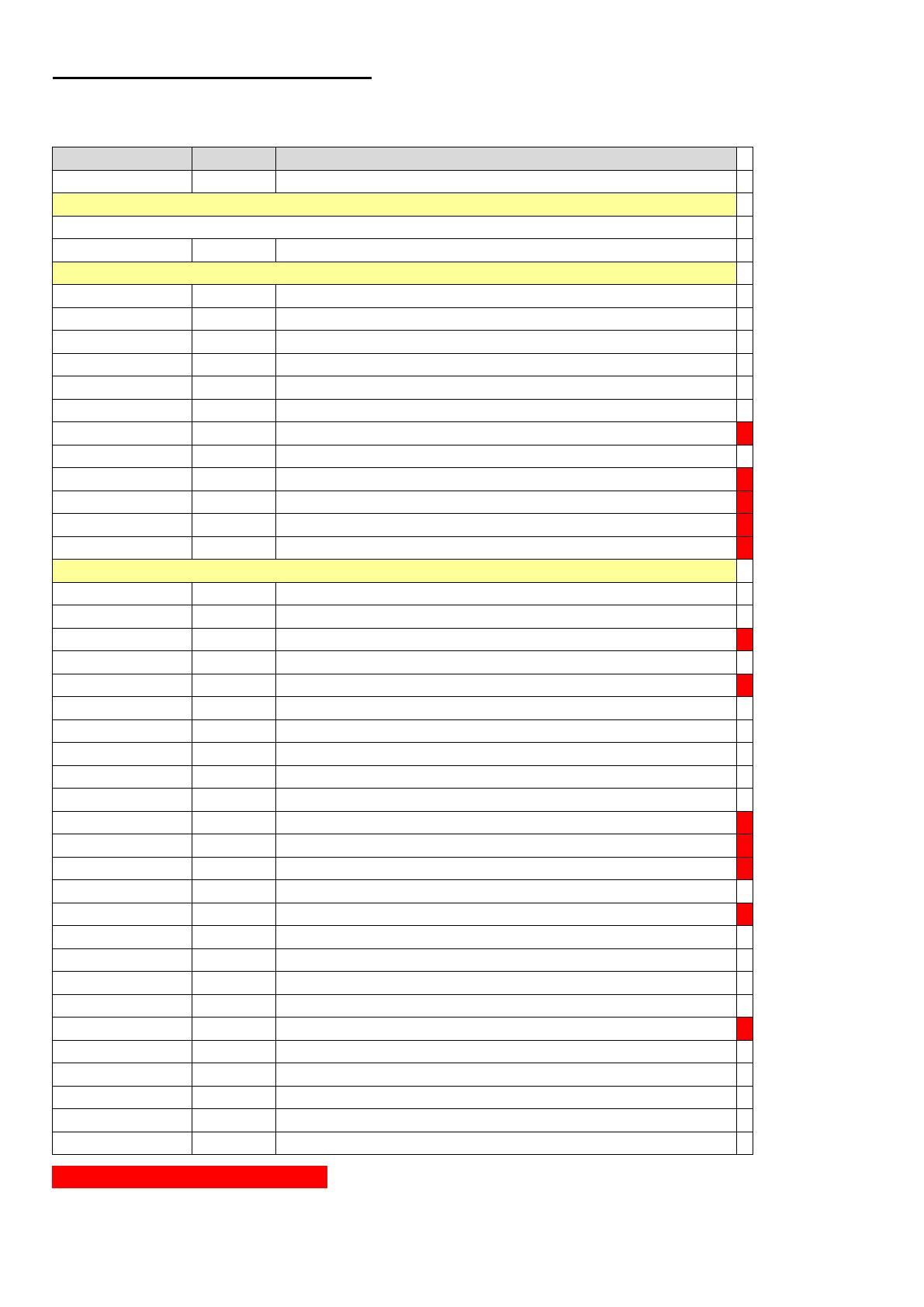
MMXU: Measured quantities of a three-phase systems
This node provides instantaneous measurements of an unbalanced multi-phase system
Attribute Name Attr. Type Explanation
LNName Shall be inherited from Logical-Node Class (see IEC 61850-7-2)
Data
Common Logical Node Information
LN shall inherit all Mandatory Data from Common Logical Node Class
Measured values
TotW MV Total Active Power (Total P)
TotVAr MV Total Reactive Power (Total Q)
TotVA MV Total Apparent Power (Total S)
TotPF MV Average Power factor (Total PF)
Hz MV Frequency
PPV DEL Phase to phase voltages (V12,V23,V31)
PhV WYE Phase to ground voltages (V1N,V2N,V3N,VNE)
A WYE Phase currents (I1, I2, I3, In)
W WYE Phase active power (P1,P2,P3)
VAr WYE Phase reactive power (QL1,QL2,QL3)
VA WYE Phase apparent power (S1,S2,S3)
PF WYE Phase power factor (PF1, PF2, PF3)
Private Extensions
IB WYE Phase bimetal currents (IB1, IB2, IB3)
TotQF MV Average reactive power factor (Total QF)
QF WYE Phase reactive power factor (QF1, QF2, QF3)
TotLF MV Average LF factor (Total LF)
LF WYE Phase reactive power factor (LF1, LF2, LF3)
Umean MV Mean values of voltages
Imean MV Mean value of currents
MaxTotW MV Maximum of total Active Power (Total P) since last reset
MaxTotVAr MV Maximum of total Reactive Power (Total Q) since last reset
MaxTotVA MV Maximum of total Apparent Power (Total S) since last reset
MaxWabc WYE Maximum of active power (P1, P2, P3) since last reset
MaxVArabc WYE Maximum of reactive power (Q1, Q2, Q3) since last reset
MaxVAabc WYE Maximum of apparent power (S1, S2, S3) since last reset
MaxPPV DEL Maximum of phase to phase voltages V12, V23, V31 since last reset
MaxPhV WYE Maximum of phase to ground voltages V1N,V2N,V3N,VNE since last reset
MaxA WYE Maximum of phase currents I1, I2, I3, In since last reset
MaxIB WYE Maximum of phase bimetal currents (IB1, IB2, IB3)
MaxHz MV Maximum of frequency since last reset
MinPPV DEL Minimum of phase to phase voltages V12, V23, V31 since last reset
MinPhV WYE Minimum of phase to ground voltages V1N,V2N,V3N since last reset
MinHz MV Minimum frequency since last reset
MinSupPFind MV Minimum power factor supply inductive load since last reset
MinSupPFcap MV Minimum power factor supply capacitive load since last reset
MinDmdPFind MV Minimum power factor demand inductive load since last reset
MinDmdPFcap MV Minimum power factor demand capacitive load since last reset
Unbalanced 4-wire systems only
24/25
MSQI -
Sequence and imbalance
This node provides data of the imbalance analysis of 3 or 4-wire systems with unbalanced load
Attribute Name Attr. Type Explanation
LNName Shall be inherited from Logical-Node Class (see IEC 61850-7-2)
Data
Common Logical Node Information
LN shall inherit all Mandatory Data from Common Logical Node Class
Measured values
SeqA SEQ Absolute measured values of positive, negative and zero sequence current.
SeqV SEQ Absolute measured values of positive, negative and zero sequence voltage.
ImbA WYE
Deviation from the average phase current.
ImbA.phsX =| I
x
− I
ave
| with Iave = (1/3) ×(I
A
+ I
B
+ I
C
)
ImbNgA MV Current Imbalance Negative Sequence Method. ImbNgA = I2 / I1
ImbNgV MV Voltage Imbalance Negative Sequence Method. ImbNgV = V2 / V1
ImbPPV DEL
Deviation from the average phase-to-phase voltage.
ImbPPV.phsXY = |V
XY
PPV
ave
| with PPV
ave
= (1/3) × (V
ab
+ V
bc
+ V
ca
).
ImbV WYE
Deviation from the average phase-to-neutral voltage.
ImbV.phsX = |V
X
– V
ave
| with Vave = (1/3) × (V
an
+ V
bn
+ V
cn
).
ImbZroA MV Current Imbalance Zero Sequence Method. ImbZroA = I0 / I1
ImbZroV MV Voltage Imbalance Zero Sequence Method. ImbZroV = V0 / V1
MaxImbA MV
Maximum deviation from the average current.
Max(Idev_a,Idev_b,Idev_c)
MaxImbPPV MV
Maximum deviation from the average phase-to-phase voltage.
MaxImbPPV = Max(PPVdev_a,PPVdev_b,PPVdev_c)
MaxImbV MV
Maximum deviation from the average phase-to-neutral voltage.
MaxImbV = Max(Vdev_a,Vdev_b,Vdev_c)
Unbalanced 4-wire systems only
Unbalanced 3-wire systems only
Balanced 3-wire systems only
25/25
MSTA: Metering statistics
Attribute Name Attr. Type Explanation
LNName Shall be inherited from Logical-Node Class (see IEC 61850-7-2)
Data
Common Logical Node Information
LN shall inherit all Mandatory Data from Common Logical Node Class
Measured values
AvAmps MV Average current system (single phase measurement only)
MaxAmps
MV
Maximum current system (single phase measurement only)
MinAmps MV Minimum current system (single phase measurement only)
AvVolts MV Average voltage system (single phase measurement only)
MaxVolts MV Maximum voltage system (single phase measurement only)
MinVolts MV Minimum voltage system (single phase measurement only)
AvVA MV Average apparent power
MaxVA MV Maximum apparent power
MinVA MV Minimum apparent power
AvW MV Average real power
MaxW MV Maximum real power
MinW MV Minimum real power
AvVAr MV Average reactive power
MaxVAr
MV
Maximum reactive power
MinVAr MV Minimum reactive power
Private Extensions
AvA WYE Average phase currents (I1, I2, I3, In)
MaxA WYE Maximum phase currents (I1, I2, I3, In)
MinA WYE Minimum phase currents (I1, I2, I3, In)
AvPPV DEL Average phase to phase voltages (V12, V23, V31)
MaxPPV DEL Maximum phase to phase voltages (V12, V23, V31)
MinPPV DEL Minimum phase to phase voltages (V12, V23, V31)
AvPhV WYE Average phase to ground voltages (V1N,V2N,V3N,VNE)
MaxPhV WYE Maximum phase to ground voltages (V1N,V2N,V3N,VNE)
MinPhV WYE Minimum phase to ground voltages (V1N,V2N,V3N,VNE)
AvVAPh
WYE
Average of apparent power (S1, S2, S3)
MaxVAPh WYE Maximum of apparent power (S1, S2, S3)
MinVAPh WYE Minimum of apparent power (S1, S2, S3)
AvWPh WYE Average of active power (P1, P2, P3)
MaxWPh WYE Maximum of active power (P1, P2, P3)
MinWPh WYE Minimum of active power (P1, P2, P3)
AvVArPh WYE Average of reactive power (Q1, Q2, Q3)
MaxVArPh WYE Maximum of reactive power (Q1, Q2, Q3)
MinVArPh WYE Minimum of reactive power (Q1, Q2, Q3)
Unbalanced 4-wire systems only
Unbalanced 3-wire systems only
Single phase or balanced 3-wire systems only
  • Page 1 1
  • Page 2 2
  • Page 3 3
  • Page 4 4
  • Page 5 5
  • Page 6 6
  • Page 7 7
  • Page 8 8
  • Page 9 9
  • Page 10 10
  • Page 11 11
  • Page 12 12
  • Page 13 13
  • Page 14 14
  • Page 15 15
  • Page 16 16
  • Page 17 17
  • Page 18 18
  • Page 19 19
  • Page 20 20
  • Page 21 21
  • Page 22 22
  • Page 23 23
  • Page 24 24
  • Page 25 25

Gossen MetraWatt SINEAX CAM Installation guide

Type
Installation guide
This manual is also suitable for

Ask a question and I''ll find the answer in the document

Finding information in a document is now easier with AI