Page is loading ...

®
SD-R400-BQ
Microwave RTE Sensor
Manual
Features:
12~24 VDC Operating voltage
24.150GHz Microwave Doppler technology
10ft (3m) Sensing range, adjustable
Adjustable relay output time, 1~33 s
Small size allows for a wide range
of applications
Universally compatible, install the sensor
above doors for no-touch ingress/egress
More consistent detection in large areas
and over a wide range of temperatures
Indoor use only

ENFORCER Microwave RTE Sensor
2 SECO-LARM U.S.A., Inc.
The ENFORCER Microwave RTE Sensor is a compact motion sensor with an adjustable output
timer that can be connected to an access control keypad, gate opener, and can be used to trigger
any device with an egress input.
1x Microwave sensor 2x Mounting screws 1x Mounting template
1x 5-Pin connector cable 1x Manual
Operating voltage 12~24 VDC
Current
draw
Standby 23mA@12VDC / 14mA@24VDC
Active 39mA@12VDC / 21mA@24VDC
Sensor frequency 24.150GHz
Sensor range 3'~10' (0.9~3m), adjustable
Sensor
angle
Vertical 0°~90°
Horizontal ±30°
Detection
angle
Front/back 20°~30°
Left/right 60°~70°
Min. detection speed 5cm/s
Output relay 2A@30VDC (0.5A@125VAC) Dry relay, NO/NC/COM
Relay output time 1~33 s
Mounting height 6'~10' (1.8~3 m)
Cable length 8' (2.5m)
LED Indicator Red on relay activation
Case material Black ABS and polycarbonate
Operating temperature -4°~131° F (-20°~55° C)
Dimensions 3
1
/
8
"x2
3
/
8
"x2
1
/
8
" (80x60x54 mm)
Weight 2.5-oz (70g)
Specifications:
Overview:
Introduction:
Parts List:
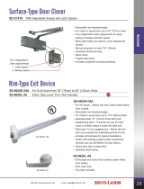
Front
3
1
/
8
"(80mm)
2
3
/
8
"
(60mm)
Side
2
1
/
8
" (54mm)
LED Indicator
Microwave
emitter
p
ad
Front
(cover removed)
Connector
cable hole

ENFORCER Microwave RTE Sensor
SECO-LARM U.S.A., Inc. 3
Installation:
Detection Area:
How to Remove the Cover Once Installed:
Side view
1. Find a suitable mounting location no more than 10ft (3m) high.
2. Apply the mounting template to the wall where the sensor is to be mounted.
3. Mark the locations for the screws, and drill one hole to the right of where it says "Insert connector here."
4. Remove the cover as described in How to Remove the Cover Before Installation, see below.
NOTE: Make sure not to touch the microwave emitter pad once the cover is removed
5. Connect the 5-pin connector cable to the microwave sensor and feed the opposite end through the
connector hole in the wall and complete wiring as necessary. See pg. 4 for Wiring Diagram.
6. Secure the microwave sensor to the wall with both screws.
7. Adjust the sensor's vertical angle and rotation as necessary.
NOTE: Grip the sensor above and below the emitter pad. Do not pinch the sides as it may damage
the trimpots.
8. Adjust the sensor's range and relay's output time using the two trimpots, see Adjusting the Sensor Range
and Relay Output Time on pg. 4, and replace the cover.
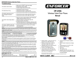
Horizontal Area of Detection:
Vertical Area of Detection:
1. The vertical area of detection will change
depending on the vertical tilt angle of the
sensor.
2. Mounted 7ft (2.1m) tall at center 0° with a
45° vertical tilt, the area of detection extends
to 6ft (1.8m).
1. The horizontal area of detection will
change depending on the horizontal tilt
angle of the sensor.
2. Mounted 7ft (2.1m) tall at center 0°, the
area of detection is 5ft (1.5m) wide and
5ft (1.5m) deep.
-30°~+30°
0°~90°
Units: meter (m)
0
1
1.5
2
0
1
2
3
2 1.5 1 0 1 1.5 2
2 1 0 1 2
1. Insert a screwdriver into the hole at the top of the sensor cover.
2. Apply moderate downward pressure to pry the cover off and
away from the sensor base.
How to Remove the Cover Before Installation:
1. Squeeze the sides of the cover and wedge a thin flat-head
screwdriver into the gap between the cover and the sensor base.
2. Apply moderate upward pressure to pry the cover off and away
from the sensor base.
NOTE: Take care to inset the screwdriver into the gap between the
cover and sensor base, and not into the recessed area of the base
j
ust below.
Back view

ENFORCER Microwave RTE Sensor
4 SECO-LARM U.S.A., Inc.
Adjusting the Sensor Range and Relay Output Time:
Wiring Diagram:
LED is off
Sensor power is off.
Check wiring and plug into power supply.
Door is not reacting normally
Make sure door is in automatic mode.
Check the output configuration of the sensor. Typical wiring for
the sensor's output is N.O.
The door opens and closes on its own
Sensor is disturbed when the door closes due to motion and
vibrations.
Make sure the sensor is properly secured.
Adjust microwave emitter pad angle.
Reduce detection area size.
Door opens for no reason
Adjust the angle and range of sensor.
SECO-LARM
®
U.S.A., Inc.
16842 Millikan Avenue, Irvine, CA 92606 Website: www.seco-larm.com
Phone:
(
949
)
261-2999
|
(
800
)
662-0800 Email: sales
@
seco-larm.com
PICQN1
MI_SD-R400-BQ_190625.docx
NOTICE: The SECO-LARM policy is one of continual development and improvement. For that reason, SECO-LARM
reserves the right to change specifications without notice. SECO-LARM is also not responsible for misprints. All trademarks
are the property of SECO-LARM U.S.A., Inc. or their respective owners. Copyright © 2019 SECO-LARM U.S.A., Inc. All
rights reserved.
WARRANTY:
This SECO-LARM product is warranted against defects in material and workmanship while used in normal
service for one (1) year from the date of sale to the original customer. SECO-LARM’s obligation is limited to the repair or
replacement of any defective part if the unit is returned, transportation prepaid, to SECO-LARM. This Warranty is void if
damage is caused by or attributed to acts of God, physical or electrical misuse or abuse, neglect, repair or alteration,
improper or abnormal usage, or faulty installation, or if for any other reason SECO-LARM determines that such equipment
is not operating properly as a result of causes other than defects in material and workmanship. The sole obligation of
SECO-LARM and the purchaser’s exclusive remedy, shall be limited to the replacement or repair only, at SECO-LARM’s
option. In no event shall SECO-LARM be liable for any special, collateral, incidental, or consequential personal or property
damage of any kind to the purchaser or anyone else.
FCC COMPLIANCE STATEMENT FCC ID: K4ER400BQ
THIS DEVICE COMPLIES WITH PART 15 OF THE FCC RULES. OPERATION IS SUBJECT TO THE FOLLOWING TWO
CONDITIONS: (1) THIS DEVICE MAY NOT CAUSE HARMFUL INTERFERENCE AND (2) THIS DEVICE MUST ACCEPT
ANY INTERFERENCE RECEIVED, INCLUDING INTERFERENCE THAT MAY CAUSE UNDESIRED OPERATION.
Notice: The changes or modifications not expressly approved by the party responsible for compliance could void the user’s
authority to operate the equipment.
IMPORTANT NOTE: To comply with the FCC RF exposure compliance requirements, no change to the antenna or the
device is permitted. Any change to the antenna or the device could result in the device exceeding the RF exposure
re
q
uirements and void user’s authorit
y
to o
p
erate the device.
IMPORTANT: Users and installers of this product are responsible for ensuring that the installation and configuration of this
product complies with all national, state, and local laws and codes related to locking and egress devices. SECO-LARM will
not be held responsible for the use of this product in violation of any current laws or codes.
1. To adjust the sensor's range, turn the trimpot counterclockwise
(decrease) or clockwise (increase). Min: 3ft (0.9m) / Max: 10ft (3m)
2. To adjust the relay output time, turn the trimpot counterclockwise
(decrease) or clockwise (increase).
Min: 1 second / Max: 33 seconds
Time
Distance
Troubleshooting:
Sensor range
Output time
Min. Max. Min. Max.
Relay outpu
t
time trimpot
Black wire: +12~24 VDC
Brown wire: (-) Ground
Yellow wire: N.C.
Green wire: COM
Gra
y
wire: N.O.
Sensor range
trimpot
/