SECO-LARM SD-9773-KNEVQ User manual

Type
User manual

This manual is also suitable for

SD-9773-KNEVQ
Surface-Mount Wave-to-Open Sensor
with Manual Override Button
Manual
Features:
Adjustable sensor range up to 6" (15cm)
1A relay, adjustable trigger duration 0.5~30
seconds or toggle
LED illuminated sensor area for easy
identification
Selectable LED colors (turns from red to
green or green to red) when sensor is
activated
Aluminum alloy and ABS plastic housing
IP54 Weather-resistant for outdoor use
ENFORCER Surface-Mount Wave-to-Open Sensor with Manual Override Button
2
SECO-LARM
U.S.A., Inc
Introduction:
The ENFORCER Surface-Mount Wave-to-Open Sensor with Manual Override Button is a full-featured
exit plate which uses IR technology to allow egress from a protected area or activate a device with the
simple wave of a hand. Since no touch is required, this sensor is suitable for use in hospitals, clinics,
labs, cleanrooms (to reduce the risk of contamination), schools, factories, or offices. A manual
override allows for operation if the sensor is disabled.
Overview:
Parts List:
1x IR Proximity sensor 1x 5-Pin wiring harness 3x Wires for override button
4x Mounting screws 2x Screw plugs 1x Manual
Specifications:
Power 12~24 VDC
Current
drain
(max.)
Standby (red) 20mA@12VDC / 26mA@24VDC
Triggered (green) 26mA@12VDC / 32mA@24VDC
Standby (green) 16mA@12VDC / 20mA@24VDC
Triggered (red) 31mA@12VDC / 39mA@24VDC
Relay type SPDT dry contact, 1A@24VDC
Response time 10ms
LEDs
Standby Red
Triggered Green
Output time 0.5~30 s, toggle
Range 1
9
/
16
"~6" (4~15 cm)
IP rating IP54
Housing material Aluminum alloy with ABS plastic
Operating temperature -4°~131° F (-20°~55° C)
Dimensions 3
1
/
8
"x 4
1
/
2
"x1
1
/
8
" (80x115x28mm)
Weight 9.5-oz (270g)
Color function reversible
When properly installed
To disassemble for wiring and mounting:
1. Remove the two screws at the bottom and remove the manual override assembly.
2. Slide the sensor plate downward along with the plastic rails to remove them from the housing.
WAVE TO OPEN
Manual Override
3
1
/
8
"
(80mm)
1
1
/
8
"
(28mm)
WAVE TO OPEN
Manual Override
4
1
/
2
"
(115mm)
WAVE TO OPEN
Manual Override
Rubber sealing pad
SPDT Manual
override
5-Pin
connector
LED Control
jumper
Trigger time
adjustment
Sensor range
adjustment
Sensor Back
Manual override assembly
ENFORCER Surface-Mount Wave-to-Open Sensor with Manual Override Button
SECO-LARM
U.S.A., Inc 3
Mounting and Wiring Diagram:
Installation:
1. Drill holes as shown above and mount the enclosure base. For weatherproof installation, install to a
flat surface so the rubber sealing pad has a good seal. Otherwise apply silicone sealant (not
included) around the back of the base before installing. Thread the wires through the wiring hole.
2. Connect the wires from to the Request-to-Exit Sensor according the Wiring Diagram above.
3. Slide the sensor plate and plastic mounting rails into the enclosure base and use the two screws to
attach the manual override assembly taking care not to crimp the wires (see Overview, pg. 2).
4. Tamp the screw plugs into the holes. Remove clear protective film from the sensor before use.
WARNING: Do not connect any device that will exceed 1A@24VDC.
Changing the LED Color Jumper Placement:
Adjusting the sensor range and trigger time:
1. The sensor range can be adjusted from 1
9
/
16
"~6" (4~15 cm).
2. The trigger time can be adjusted from 0.5~30 seconds or toggle.*
NOTE: Do not force the adjustment trimpots to turn. Only minimal
force is needed.
Standby: Green
Trigger: Red
Standby: Red
Trigger: Green
(default)
C
OM
Use disassembled enclosure
base as a template to mark the
locations of the 4 mounting holes
and wiring hole for drilling.
Red Wire: +12~24VDC
Brown Wire: Ground (-)
Blue Wire: COM
Purple Wire: N.O.
Green Wire: N.C.
NC
NO
Manual
override
assembly
Relay (N.O.)
Relay (COM)
Relay (N.C.)
– GND
+ 12~24VDC
5
-
Pin Terminal
Sensor
plate
Green
wire
Blue
wire
Trigger time
adjustment
Sensor range
adjustment
Sensor Back
Screw plugs
Housing assembly
screws
Screw Plugs:
Trigger time: 0.
5
~
3
0 seconds, toggle
*
Default: 0.5 seconds
*Set trigger time to maximum for toggle
0.
5s
30
s
Sensor range: 1
9
/
16
"~6" (4~15 cm)
Default: 6" (15cm)
15cm
4cm
ENFORCER Surface-Mount Wave-to-Open Sensor with Manual Override Button
4
SECO-LARM
U.S.A., Inc
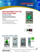
Sample Installation:
Typical installation with an electric lock:
Care and Cleaning of the Sensor:
The sensor requires special care to ensure reliability and a long operating life.
1. Use a soft, clean cloth for cleaning. Use the mildest type of cleaner available.
2. When cleaning, spray the cleaning solution onto the cleaning cloth instead of the unit.
3. Be sure to wipe off any excess liquid from the sensor. Wet spots may affect the sensor’s
performance.
California Proposition 65 Warning
:
These
products may contain chemicals which are known to the State of California
to cause cancer and birth defects or other reproductive harm. For more information, go to www.P65Warnings.ca.gov.
NOTICE
:
The SECO
-
LARM policy is one of continual development and improvement. For that reason, SECO
-
LARM
reserves the right to change specifications without notice. SECO-LARM is also not responsible for misprints.
All
trademarks are the property of SECO-LARM U.S.A., Inc. or their respective owners. Copyright © 2020
SECO-LARM U.S.A., Inc. All rights reserved.
WARRANTY:
This SECO
-
LARM product is warranted against defects in material and workmanship while
used in normal
service for one (1) year from the date of sale to the original customer. SECO-
LARM’s obligation is limited to the repair or
replacement of any defective part if the unit is returned, transportation prepaid, to SECO-LARM.
This Warranty is void if
damage is caused by or attributed to acts of God,
physical or electrical misuse or abuse, neglect, repair or alteration,
improper or abnormal usage, or faulty installation, or if for any other reason SECO-
LARM determines that such
equipment is not operating properly as a result of causes other than defects in material and workmanship.
The sole
obligation of SECO-LARM
and the purchaser’s exclusive remedy, shall be limited to the replacement or repair only, at
SECO-LARM’s option. In no event shall SECO-LARM be liable for any special, collateral, incidental,
or consequential
personal or property damage of any kind to the purchaser or anyone else.
IMPORTANT:
Users and installers of this product are responsible for ensuring that the installation and configuration of
this product complies with all national, state, and local laws and codes related to locking and egress devices.
SECO-LARM will not be held responsible for the use of this product in violation of any current laws or codes.
IMPORTANT WARNING:
For a weatherproof installation, ensure the unit is installed
so
that the
re is a good seal between
the enclosure base and the mounting surface
. Incorrect mounting may lead to exposure to rain or moisture in the
enclosure which could cause a dangerous electric shock, damage the device, and void the warranty. Users and installers
of this product are responsible for ensuring this product is properly installed and sealed.
SECO-LARM
®
U.S.A., Inc.
16842 Millikan Avenue, Irvine, CA 92606
Website:
www.seco
-
larm.com
Phone: (949) 261
-
2999 | (800) 662
-
0800
Email: sales@seco
-
larm.com
PITSW
2
MI_SD
-
9773
-
KNEVQ_201123.docx
Green wire
Blue
wire
  • Page 1 1
  • Page 2 2
  • Page 3 3
  • Page 4 4

SECO-LARM SD-9773-KNEVQ User manual

Type
User manual
This manual is also suitable for

Ask a question and I''ll find the answer in the document

Finding information in a document is now easier with AI