Page is loading ...

Adult Turkey Feeder Manual
Page 1
MF232M52
• Adult Turkey Feeder Installation Manual •
Adult Turkey Feeder
Installation Manual
September 1996

Adult Turkey Feeder Manual
Page 2
Support Information
(CE-mark serial number)
The Chore-Time Adult Turkey Feeder is designed to feed turkeys. Using this
equipment for any other purpose or in a way not within the operating recommen-
dations specified in this manual will void the warranty and may cause personal
injury and/or death.
This manual is designed to provide comprehensive planning, installation, wiring,
operation, and parts listing information. The Table of Contents on page 3 provides
an convenient overview of the information in this manual. The Table of Contents
also specifies which pages contain information for the sales personal, installer,
distributor, and consumer (end user).
Chore-Time Equipment recognizes CE Mark and pursues compliance in all appli-
cable products. Fill in the CE-Mark serial number in the blank space provided for
future reference.
Please fill in the following information about your Adult Turkey Feeding System.
Keep this manual in a clean, dry place for future reference.
Distributor’s Name
Distributor’s Address
Distributor’s Phone Date of Purchase
Installer’s Name
Installer’s Address
Installer’s Phone Date of Installation
System Specifications
Feed Delivery System Supplying
Chore-Time Equipment, A Division of CTB, Inc.
P.O. Box 2000, Milford, Indiana 46542-2000 U.S.A.
Phone: 219-658-4101 • Fax: 219-658-4133 • E-Mail: ctb@ctbinc.com

Adult Turkey Feeder Manual
Page 3
Table of Contents
Topic Page User
Support Information.. .. .. .. .. .. .. .. .. .. .. .. .. .. .. .. .. .. .. 2 C, D
Safety Information .. .. .. .. .. .. .. .. .. .. .. .. .. .. .. .. .. .. 4 - 5 C, I
Glossary of Terms .. .. .. .. .. .. .. .. .. .. .. .. .. .. .. .. .. .. .. 5 C, I, S
Feeder Assembly . .. .. .. .. .. .. .. .. .. .. .. .. .. .. .. .. .. 6 - 12 I
Stage II Feeder Assembly .. .. .. .. .. .. .. .. .. .. .. .. .. 7 - 8 I
Adult Turkey Feeder Assembly .. .. .. .. .. .. .. .. .. .. .. 8 - 9 I
Feeder Tube Assembly .. .. .. .. .. .. .. .. .. .. .. .. .. 9 - 10 I
Control Unit Installation .. .. .. .. .. .. .. .. .. .. .. .. .. 10 - 12 I
Suspension System.. .. .. .. .. .. .. .. .. .. .. .. .. .. .. .. .. 13 - 19 I
Screw Hook Installation .. .. .. .. .. .. .. .. .. .. .. .. .. .. . 16 I
Ceiling Hook Installation.. .. .. .. .. .. .. .. .. .. .. .. .. 17 - 18 I
Power Winch Installation . .. .. .. .. .. .. .. .. .. .. .. .. 18 - 19 I
Drop Installation.. .. .. .. .. .. .. .. .. .. .. .. .. .. .. .. .. . 19 I
Hopper Assembly Procedure .. .. .. .. .. .. .. .. .. .. .. .. . 19 I
Feeder Line Assembly & Suspension .. .. .. .. .. .. .. .. .. .. 20 - 31 I
Anti-Roost Installation . .. .. .. .. .. .. .. .. .. .. .. .. .. 22 - 24 I
Auger Installation .. .. .. .. .. .. .. .. .. .. .. .. .. .. .. 25 - 27 I
Winch Adjustable Feed Level Tubes--Optional Equipment.. .. .. 28 - 31 I
Intermediate Control--Optional Equipment. .. .. .. .. .. .. .. .. 31 - 32 I
Intermediate Control Operation .. .. .. .. .. .. .. .. .. .. .. . 32 C
Control Installation --Optional Equipment .. .. .. .. .. .. .. .. .. .. . 33 I
ATF Recommendations & Guidelines. .. .. .. .. .. .. .. .. .. .. .. . 33 C, I
End & Intermediate Control Wiring Diagrams: Single Phase .. .. .. . 34 E
End & Intermediate Control Wiring Diagrams: Three Phase .. .. .. . 35 E
26230 Time Clock Control Wiring Diagram. .. .. .. .. .. .. .. .. .. . 36 E
26230 Time Clock Control Internal Wiring Diagram .. .. .. .. .. .. . 36 E
200# Hopper Assembly Parts List . .. .. .. .. .. .. .. .. .. .. .. .. . 37 C
Feeder Line Components.. .. .. .. .. .. .. .. .. .. .. .. .. .. .. .. . 37 C
Adult Turkey Feeder Components . .. .. .. .. .. .. .. .. .. .. .. .. . 38 C
ATF Power Unit Components .. .. .. .. .. .. .. .. .. .. .. .. .. .. . 39 C
ATF Control Unit Components: Part No. 27905 .. .. .. .. .. .. .. .. . 40 C
ATF Control Unit Components: Part No. 6035 .. .. .. .. .. .. .. .. . 40 C
Drop Tube Assemblies.. .. .. .. .. .. .. .. .. .. .. .. .. .. .. .. .. . 42 C
ATF Intermediate Control: Part No. 6039 .. .. .. .. .. .. .. .. .. .. . 43 C
Single Boot Components: Part No. 6821 .. .. .. .. .. .. .. .. .. .. . 44 C
Twin Boot Components: Part No. 8460 .. .. .. .. .. .. .. .. .. .. .. . 44 C
2883 Power Winch .. .. .. .. .. .. .. .. .. .. .. .. .. .. .. .. .. .. . 45 C
Miscellaneous Suspension Components .. .. .. .. .. .. .. .. .. .. . 46 C
Maintaning the Adult Turkey Feeding System .. .. .. .. .. .. .. 47 - 48 C
Trouble Shooting the Adult Turkey Feeding System .. .. .. .. .. 49 - 50 C
Warranty Information .. .. .. .. .. .. .. .. .. .. .. .. .. .. .. .. .. . 51 C, D
Table of Contents Legend: Customer (C), Distributor (D), Electrician (E), Installer (I), Salesperson (S)

Adult Turkey Feeder Manual
Page 4
SAFETY INFORMATION
CHORE-TIME is concerned about the safety of it’s customers. Caution, Warning and Danger Decals have been
placed on the equipment to warn of potentially dangerous situations. Care should be taken to keep this information
intact and easy to read at all times. Replace missing or damaged safety signs.
Use the equipment as specified in these instructions. Unreasonable use of the equipment may cause personal injury
or damage to the equipment.
Safety-Alert Symbol
This is a safety-alert symbol. When you see this symbol on your equipment, be
alert to the potential for personal injury.
DANGER
WARNING
CAUTION
Signal Words
Signal words are used in conjunction with the safety-alert symbol to
identify the severity of the warning.
DANGER ..........identifies immediate hazards which WILL
result in severe personal injury or death.
WARNING........identifies hazards or unsafe practices which
COULD result in severe personal injury or
death.
CAUTION.........identifies hazards or unsafe practices which
COULD result in minor personal injury or
product or property damage.
DANGER--MOVING AUGER
This decal is placed on the Clean-Out Cover of
the FLEX-AUGER Control Unit.
Severe personal injury will result, if the electrical
power is not disconnected, prior to servicing the
equipment.
DANGER--ELECTRICAL HAZARD
Disconnect electrical power before inspecting or servicing equipment
unless maintenance instructions specifically state otherwise.
Ground all electrical equipment for safety.
All electrical wiring must be done by a qualified electrician in accordance
with local and national electric codes.
Ground all non-current carrying metal parts to guard against electrical
shock.
With the exception of motor overload protection, electrical disconnects
and over current protection are not supplied with the equipment.

Adult Turkey Feeder Manual
Page 5
SAFETY INFORMATION
Use caution when working with the
Auger--springing auger may cause personal injury.
CAUTION

Adult Turkey Feeder Manual
Page 6
Electro-Guard:.. . .. . .. . .. A high voltage, low
current shocking
device used to keep
birds from setting
on the feeder line.
Clamp: . . .. . .. . .. A two-piece, riveted strap
used to secure 15 auger
tubes together.
Adjustment Leveler: .. . . A cable locking de-
vise used to conve-
niently adjust the
feeder to a level po-
sition.
Throw-back: . .. . .. . .. . .. A cable/pulley arrangement
that allows cable to be routed to a desired location.
Power Lift: .. . .. . .. . .. . .. Red, cast iron winch used to raise
and lower the feeder line(s). Oper-
ated by a hand crank or electric
drill. Referred to as Power Winch.
Drop Line: .. . .. . .. . .. . .. A section of cable fas-
tened to the main ca-
ble, routed through a
pulley, down to the
feeder line.
Glossary of Terms
Anti-Roost Bracket: . . .. . .. .An insulator
and bracket assembly
mounted on every fourth
or fifth clamp to support
shocker wire.
Double-back: . .. . .. . .. . .. A cable/pulley arrange-
ment that reduces the load on the Power Winch.
Intermediate Control: .. . A feeder, equipped
with a switch, (locat-
ed near the center of the
feeder line) used to
control the feeding
system when partial
house brooding.
End Control: . .. . .. . .. . .. A feeder, equipped
with a switch, (located
at the power unit),
used to control the
feeding system.

Adult Turkey Feeder Manual
Page 7
Feeder Assembly
1. Attach one Swing Down Pan Support and three regular Pan Supports to Pan
Shield using rivets supplied. Always attach the Swing Down Pan Support at the
same location on all pan shields. It will be necessary to support the Pan Shield
while installing the rivets. Use a hammer to drive rivets as shown in Figure 1.
2. Determine which Feeder Pan (Adult Turkey or Stage II) is to be installed. See
Figure 2. Refer to the appropriate section below.
The basic assembly and installation of the Stage II Feeder is the same as the
Adult Turkey Feeder. The two primary differences being; 1) the feeder pan
design, and 2) installation of the Feed Level Tube.
Figure 1. Pan shield Assembly (side view)
Key Description
1 Pan Shield
2 Wood Block (not supplied)
3 Pan Support
Stage II Feeder Assembly
Assemble the Feed Level Tube & Ring with the arrow pointing down, when the Stage
II Pan is used. See Figure 3.
The Feed Level Ring should be positioned in the second hole from the top for Stage
II Feeder Pans. Note the direction of the arrow.
Key Description
1 Stage II Feeder Pan
2 Adult Turkey Feeder Pan
Figure 2. Feeder Pans (side view)

Adult Turkey Feeder Manual
Page 8
Figure 2.
Figure 3. Stage II Feed Level Ring (side view)
Figure 5. Cable Installation
3. If the Feed Level Tubes are to be winch adjustable, install the Cable Assemblies
at this point. If the Feed Level Tubes are not to be winchable, proceed to step 4.
Install two cables at each feed level tube, as shown in Figure 5. The cable stop
should be located on the inside of the Feed Level Tube and pulled up tight against
the inside.
NOTE: After the feeder operates, re-adjustment of the Feed Level Tubes may be
desired to achieve the desired feed level.
Adult Turkey Feeder Assembly
Assemble the Feed Level Tube and Feed Level Ring, as shown in Figure 4.
Note the direction of the arrow on the side of the Feed Level Tube.
Position the Feed Level Ring in the third hole from the bottom for the Adult Turkey
Feeder Pan. See Figure 4.
Key Description
1 Stage II Feed Level Tube
2 Stage II Feed Level Ring
Key Description
1 Stage II Feed Level Tube
2 Stage II Feed Level Ring
Key Description
1 Feed Level Ring
2 Cable Assembly
Figure 4. Adult Turkey Feeder Feed Level Ring (side view)

Adult Turkey Feeder Manual
Page 9
4. Place the Feed Level Tube Assembly in the Feeder Pan.
5. Insert Drop Tube into Feed Level Tube Assembly. See Figure 6. Install the Pan
Shield Supports in the slots in the Drop Tube.
6. Install the Pan Shield Assembly onto the Pan by hooking the Swing Down Pan
Support through the hole in the Pan. See Figure 7. Then swing the pan up and
snap the remaining Pan Supports over the lip of the pan.
Do not bend the Pan Supports during assembly.
Figure 6. Drop Tube Installation
Key Description
1 Drop Tube
2 Feed Level Tube Assembly
3 Pan Shield Supports
Key Description
1 Feeder Pan
2 Swing Down Pan Support
Figure 7. Hooking the Pan to the Pan Shield
Feeder Tube Assembly
1. Slide one Pan Assembly onto the Feeder Tube for each outlet hole. Lift the Drop
Tube through the Pan Shield so the Feeder Tube can slide through the holes in
the sides of the Drop Tube. Install the Pan Assemblies so that all the Swing Down
Pan Supports are on the same side of the feeder line.
2. Rotate the feeder Tube so that the tab at the outlet hole will pass through the
notch in the Drop Tube. Rotate the tube 180 degrees to lock the pans in place.
See Figure 8. Make sure outlet holes are down.
3. Position the tubes with pans attached end to end in the approximate location
where they will be suspended. The belled ends of the tubes must point
towards the hopper.

Adult Turkey Feeder Manual
Page 10
Figure 8. Install Feeders on the Auger Tubes. (side view)
Control Unit Installation
The assembly instructions are very similar for the 6035 Control Assembly and the
27905 Control Assembly. The primary differences between the controls are in the
electrical components and protection devices.
1. Remove the four 5/16-18x5/8" bolts from the parts package and use them to bolt
the Anchor Plate to the Power Unit. Install the Anchor Plate with the angled end
pointing down. See Figure 9.
2. Bolt the Control Unit Body Assembly to the Power Unit, using hardware supplied.
See Figure 9.
6035 Control Unit
27905 Control Unit
Key Description
1 Power Unit/Gear-
head
2 5/16-18 x 5/8” Bolts
3 10-24 Bolts
4 Control Unit Body
Figure 9. Install Feeders on the Auger Tubes. (side view)

Adult Turkey Feeder Manual
Page 11
3. Rivet the Pan Supports on the Control Unit Shield. See Figure 1 (on page 7) for
instructions on riveting.
4. The Feed Level Switch is factory adjusted. To check adjustment before
assembling, depress the switch paddle and listen for the switch to "click". If the
switch needs adjustment, refer to the maintenance section on pages 47 - 48.
5. Insert the Drop Tube and Switch Assembly through the Pan Shield, from the
bottom. See Figure 10. The hole in the Pan Shield should be located on the same
side of the Drop Tube as the Switch Cord and directly under the white box on the
body assembly. Bolt the Drop Tube to the Body Assembly. The switch on the Drop
Tube should be mounted
opposite the Power Unit.
6. Single Phase: Install the 90 degree connector, flexible conduit, electrical wire,
and conduit connector as shown in Figure 11.
Three Phase: Refer to applicable electrical standards for connecting Power Unit
to Control Unit. Components are not supplied by Chore-Time.
Key Description
1 Power Unit/Gearhead
2 Pan Shield Assembly
3 Drop Tube and Switch Assembly
4 Feed Level Tube & Ring
5 Feeder Pan
Figure 10. Drop Tube and Switch Assembly Installation. (side view)
Figure 11. Conduit Installation. (side view)
Key Description
190° Connector
2 Flexible Conduit
3 Conduit Connector

Adult Turkey Feeder Manual
Page 12
7. Insert the flex cable that is attached to the control switch through the hole in the
control unit pan shield and attach the Romex connector to the handy box. See
Figure 12.
8. DISCONNECT ELECTRICAL POWER PRIOR TO WIRING THE CONTROL UNIT.
Single Phase Control Unit may be wired as shown in Figure 13, or for additional
wiring, refer to the wiring diagrams on page 34.
Three Phase Control Unit must be wired as shown in the wiring diagrams on page
35.
9. Mount the control unit on the end of the feeder line and secure with a tube clamp,
as shown in Figure 9. The distance between the control unit pan and the last pan
should be five feet (1.5 m) or less.
Figure 12. Drop Tube and Switch Assembly Installation. (side view)

Adult Turkey Feeder Manual
Page 13
Suspension System
The feeder line suspension system is a vital part of your feeding system. Proper plan-
ning and installation is necessary to insure proper operation of the system.
The type of installation required depends on feeder line length. Figure 13 shows the
suspension system for feeder line lengths to 350’ (107 m). Figure 14, on page 15,
shows the suspension system for feeder lines over 350’ (107 m).
IMPORTANT: Notice that the feeder line MUST BE SUPPORTED WITHIN 1 FOOT
(300 MM) OF THE HOPPER AND 3 FEET (1 M) OF THE MOTOR ON THE CONTROL
UNIT. If the Control Unit does not come out directly under a truss, fasten a pulley to
a 2x8 (50x200 mm) board that will span 2 trusses supporting the Control Unit.
After determining the type of suspension system required, decide where the feeder
line is to be installed. Mark a straight line on the ceiling or rafters the full length of the
feeder line. Use a string, chalk line, or the winch cable, temporarily attached with sta-
ples, to mark the line. Center the line directly over where the feeder is to be installed.
The recommended distance between the drops is 8’ (2.4 m) on center. Do not exceed
10’ (3 m) spacing on drop lines.
If the distance raised is greater than the distance between the drop spacings, offset
the hooks 3" (75 mm) to each side of the line to prevent the cable clamps from catch-
ing the pulleys. See Figure 15.
For installations using wood trusses, standard screw hook or the optional Ceiling
Hook may be used to hold the pulley assemblies.
For installations using steel trusses, the Ceiling Hooks are available to hold the pulley
assemblies.
USE THE CHART BELOW AS A REFERENCE GUIDE FOR
DETERMINING SUPPORT LOAD REQUIREMENTS FOR YOUR SYSTEM
Component Weigh in pounds (kg)
Tube, Auger, Feeders, & Feed 7 lbs./ft (10.5 kg./m)
Power Unit & Control Unit Assembly 50 lbs. (22.6 kg)
200 lb. Feed Hopper & Feed 250 lbs. (113.4 kg)
Power Winch 40 lbs. (18.1 kg)

Page 14
Adult Turkey Feeder Manual
For systems up to 350’ (107 m).
K
e
y
D
e
s
c
r
i
p
t
i
o
n
1
S
w
i
v
e
l
P
u
l
l
e
y
2
F
u
l
l
L
i
n
e
S
u
s
p
e
n
s
i
o
n
K
i
t
3
1
’
(
3
0
c
m
)
4
P
o
w
e
r
W
i
n
c
h
5
3
’
(
9
0
c
m
)
6
3
.
5
”
(
8
.
9
c
m
)
P
u
l
l
e
y
Figure 13.

Page 15
Adult Turkey Feeder Manual
For systems over 350’ (107 m).
K
e
y
D
e
s
c
r
i
p
t
i
o
n
1
F
u
l
l
L
i
n
e
S
u
s
p
e
n
s
i
o
n
K
i
t
2
1
’
(
3
0
c
m
)
3
S
w
i
v
e
l
P
u
l
l
e
y
4
3
.
5
”
(
8
.
9
c
m
)
P
u
l
l
e
y
5
P
o
w
e
r
W
i
n
c
h
6
K
e
y
#
7
+
2
’
(
6
1
c
m
)
7
M
a
x
i
m
u
m
D
i
s
t
a
n
c
e
o
f
T
r
a
v
e
l
8
D
o
u
b
l
e
C
l
a
m
p
H
e
r
e
9
3
’
(
9
0
c
m
)
1
0
D
r
o
p
L
i
n
e
1
1
S
i
n
g
l
e
C
l
a
m
p
H
e
r
e
Figure 14.

Adult Turkey Feeder Manual
Page 16
Figure 15. Suspension System with Off-Sets (side view).
Figure 16. Screw Hook Installation (side view)
Screw Hook Installation
Screw the hook into the truss the full length of the threads to prevent bending. The
openings of the screw hooks must be pointed away from the direction of travel
when the Power Winch raises the feeder line. See Figure 16.
Key Description
13/16” Winch Cable
2 Screw Hook Location
33/32” Drop Cable
4 Distance of Cable Travel
5 Distance of Feeders to be Raised
Key Description
1 Screw Hook Opening
2 Cable Pull
33/16” Winch Cable
43/32” Drop Cable

Adult Turkey Feeder Manual
Page 17
Figure 17. Narrow Steel Truss Installations
Key Description
1 Secure Bracket to truss using self-drilling
screws through side-by-side holes.
2 Cable Travel
Ceiling Hook Installation
The ceiling hook may be used in a variety of installations. Depending on your indi-
vidual situation, install the Ceiling Hooks as shown in Figures 17 - 20.
After securing the Ceiling Hook to the truss, slide the hook of a Swivel Pulley into
the slot, as shown in Figure 21.
Key Description
1 Secure Bracket to truss using self-drilling
screws through opposite holes.
2 Cable Travel
Figure 18. Wide Steel Truss Installations
Key Description
1Weld Here
2 Cable Travel
Figure 19. Steel Truss Welded Installations
Key Description
1 Secure Ceiling Hook to truss using
1/4-20 Lag Screw through large
center hole.
2 Cable Travel
Figure 20. Wood Truss Installations

Adult Turkey Feeder Manual
Page 18
Key Description
1 Wood Truss
2 Ceiling Hook
31/4” Lag Bolt
4 Swivel Pulley
5 Drop Cable
Figure 21. Swivel Pulley Installation
Power Winch Installation
1. Bolt the Power Winch, fully assembled, to a 2x8 (50x200 mm) board that will span
at least 3 rafters. The brake mechanism will protrude on one side.
For feeder lines over 350 feet (106 m), install a 2985 Cable Hook between the
mounting bolt and Power Winch frame, as shown in Figure 22.
2. Attach the 2x8 (20x200 mm) board, with the Power Winch secured, to the ceiling
at the center of the feeder line. The 2x8 (50x200 mm) must be parallel to the line
and must span at least 3 rafters.
Figure 22. Power Winch Installation
If the hopper is located at the center of the feeder line, locate the Power Winch a
few feet offset from the center of the feeder line.
3. Extend the 3/16" (5 mm) cable the full length of the feeder line. Attach the cable
temporarily to the ceiling with nails, staples, or some type of fastener.
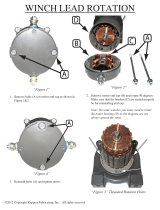
4. Wrap the cable through the winch drum relief located near the bottom of the drum.
Tighten the set screw to anchor the cable to the drum. See Figure 23.
5. Turn the winch drum one full revolution. Guide the cable against the flange at the
bottom of the winch drum. The cable must not wrap over itself on the drum, but
should be wrapped as close as possible to each previous wrap. See Figure 23.
Key Description
1 Power Winch
2Cable Hook
3 2x8 Board
4 Secure Cable Hook and
Power Winch to 2x8 Board.

Adult Turkey Feeder Manual
Page 19
Figure 23. Cable Installation & Wrap
Drop Installation
1. Attach a 3004 Pulley to each hook.
2. Thread the end of the 3/32" or 1/8" cable through the pulley toward the winch.
Clamp this end to the 3/16" winch cable about 6" (150 mm) from the pulley, using
a 3/16" cable clamp. See Figure 16.
3. Cut the cable long enough to allow for installation to the feeder line and to the
Adjustment Leveler.
Sufficient cable is included to provide "throwbacks" on drops located beneath and
near the winch. Detail D on Figure 14 (page 11) shows a "throwback" cable
arrangement.
4. Begin installing suspension drops at the winch and proceed to the ends of
the feeder line.
Keep the main cable tight between drops. It may be necessary to hang a weight
on the end of the main cable to maintain tension.
Hopper Assembly Procedure
The 200# Hopper is used with the Adult Turkey Feeder.
1. Loosely, assemble the 200# Hopper Side Panels, as shown in Figure 24, using
1/4-20 bolts and 1/4-20 hex nuts (supplied in Hardware Package). The Hopper
should be assembled so that the "CHORE-TIME" decals are on opposite sides of
the hopper.
2. Secure the Boot Hangers to the bottom of the hopper, using 1/4-20 hardware. See
Figure 24.
Key Description
1 Drum Rotation
Key Description
1 Two-Piece Cover (optional)
2 Adjustment Bracket
3 Hanger Bracket
4 Clevis Pin & Hair Pin
5 Side Panels
6 Boot Hanger
7 Tube Support Assembly
Figure 24. Hopper Assembly Procedure

Adult Turkey Feeder Manual
Page 20
Feeder Line Assembly & Suspension
1. The tubes should be laying end to end in approximately the final location of the
line. The expanded end of each tube should be toward the Hopper end of the line.
See Figure 25.
2. Connect the individual feeder tubes together by inserting the straight end of the
tube as far as possible into the belled end of the next tube.
Figure 25. Feeder Line Assembly Procedure (side view)
Key Description
1 Feed Hopper
2 Slide Feeder Tubes together.
3. Place a Tube Clamp Assembly or Clamp/Anti-Roost Bracket at each joint. Figure
26 shows the standard Clamp and Clamp/Anti-Roost Bracket.
Make sure that each tube fits as far as possible into the belled end of the next
tube. The outlet holes must point down
. Install tube clamps as shown in Figure 27.
4. Begin at the hopper end of the line. Use a tube clamp with anti-roost bracket to
attach the hopper to the first tube. Use a tube clamp (w/o insulator) at the next
joint--between the first and second feeder tubes. Continue down the line,
clamping the tubes together. Use a tube clamp with anti-roost bracket at the end
of the line. This should give a tube cable clamp with anti-roost bracket at each end
of the line and at 20 foot (6 m) intervals along the length of the line.
5. If the optional Intermediate Control Unit is used, install it at the desired location.
Refer to page 31 - 32 for Intermediate Control Installation instructions.
Figure 26. Tube Clamp and Anti-Roost Bracket (side view)
Key Description
1 Standard Clamp
2Anti-Roost
Figure 27. Tube Joint Connection (side view)
Key Description
11/4” (6 mm)
/