
1
# 123173
INSTALLATION GUIDE
CB SERIES - DEDICATED HORIZONTAL COIL
1. Safety Instruction
2. Inspection
3. Installation Preparation
4. Condensate Drain Preparation
!
WARNING
Potential safety hazards are alerted using the following symbols. The symbol is used in conjunction with terms
that indicate the intensity of the hazard.
This symbol indicates a potentially hazardous situation, which if not avoided,
could result in serious injury, property damage, product damage or death.
Certied technicians or those individuals
meeting the requirements specied by
NATE may use this information. Property
and product damage or personal injury hazard may occur
without such background.
This symbol indicates a potentially hazardous situation, which if not avoided,
may result in moderate injury or property damage.
Drain lines from the auxiliary drain pan
should NOT be connected to the primary
drain line of the coil.
If the drain pan is constructed of nylon
or plastic; use Teon tape to connect the
drain lines to the threads in the drain pan.
DO NOT USE SOLVENT BASED PIPE DOPE. THIS WILL RE-
DUCE THE LIFE OF THE PAN.
CAUTION
!
CAUTION
!
CAUTION
!
!
WARNING
All power sources should be discon-
nected prior to servicing. Failure to do
so may cause personal injury or property
damage.
!
WARNING
Product designed and manufactured to
permit installation in accordance with lo-
cal and national building codes. It is the
installer’s responsibility to ensure that product is installed
in strict compliance with national and local codes. Man-
ufacturer takes no responsibility for damage (personal,
product or property) caused due to installations violating
regulations.
!
WARNING
ü On receiving the product, visually inspect it for any major shipping
related damages. Shipping damages are the carrier’s responsibility.
Inspect the product labels to verify the model number and options
are in accordance with your order. Manufacturer will not accept dam-
age claims for incorrectly shipped product.
ü Read all the instructions in this guideline carefully while paying
special attention to the WARNING and CAUTION alerts. If any of
the instructions are unclear, clarify with a certied technician before
proceeding. Gather all tools needed for successful installation of the
unit prior to beginning the installation.
ü CS coils are designed with a built in Primary drain pan only. Please
Check local building codes for auxiliary drain pan requirements. The
auxiliary drain pan must have a separate drain line that is properly
sloped and terminated in an area visible to the home owner. The
auxiliary pans provide extra protection to the area under the unit
ü Install coil with a mininum 1/4” slope towards the drain connection.
Condensate drain lines must be installed in accordance with local
building codes.
ü The drain lines must be installed with ¼” per foot pitch to provide
free drainage. A condensate trap MUST be installed on the primary
drain line to ensure proper drainage of the condensate. The trap
must be installed in the drain line below the bottom of the drain pan.
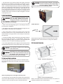
Fig. 4-1 illustrates the typical drain trap installation.
should the primary and secondary drain plug up and overow. As
expressed in our product warranty; ASPEN WILL NOT BE BILLED
FOR ANY STRUCTURAL DAMAGES CAUSE BY FAILURE TO
FOLLOW THIS INSTALLATION REQUIREMENT. The drains from
the auxiliary drain pan must be installed according to the local build-
ing codes.
Fig 4-1. Typical drain line trap set up

2
# 123173
5A. Horizontal Only Installation
ü The drain pans have a primary (white) and auxiliary (red) drain
connections. If the auxiliary line is required, it should be run spec-
trally from the primary drain line and terminated in a highly visible lo-
cation. Condensate disposal through auxiliary line indicates that the
primary line is plugged and needs cleaning. If a secondary drain line
will not be provided plug the secondary drain. Drain plugs are NOT
to be reused without plumbers tape. Drain line connection should
be nger tightened, then turned no more than one complete turn as
needed to ensure a rm connection. DO NOT overtighten connection
or damage may occur.
5. Coil Installation
ü Clean coil ns with degreasing agent or mild detergent and rinse
ns clean prior to installation.
ü The refrigerant line sizes should be selected according to the rec-
ommendations of the outdoor unit manufacturer.
ü Care must be taken to ensure all connection joints are burr-free
and clean. Failure to do so may increase chances of a leak. It is
recommended to use a pipe cutter to remove the spun closed end of
the suction line.
ü To reduce air leakage, rubber grommets may be present where the
lines pass through the coil case. To avoid damage, remove grom-
mets prior to brazing by sliding over the lines. Use a quenching cloth
or allow the lines to cool before reinstalling the grommets.
ü Use of wet rags/quenching cloth is highly recommended to prevent
weld-related damages to the casing and Schrader valve (if present).
Coil should be installed on the discharge
side of the furnace
CAUTION
!
Some Aspen coils may include a Schrader
valve on the suction manifold. Ensure that
the Schrader valve and valve core (where
present) are protected from heat to prevent leakage.
CAUTION
!
The coil is manufactured with dry nitro-
gen pre-charge. Release the pressure
through the Schrader valve test port pri-
or to installation. If holding pressure is not present, return
coil to distributor for exchange.
!
WARNING
Refer to Furnace/Air Handler manufacturer literature for specic coil
installation guidelines and recommendations.
Duct work must be installed in accordance
with the local building codes. Aspen Mfg is
will not be liable for damages caused due
by nonconformance to local building codes.
CAUTION
!
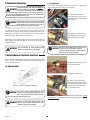
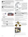
Fig 5B-1. Horizontal Left Application
Fig 5B-2. Horizontal Right Application
A dual drain pan (pan within a pan) is used for condensate collec-
tion. Condensate drain ports are located on both left and right sides
of the unit.
Primary
Auxiliary
Note: The primary drain is the higher of the two ports.
A condensate trap, as shown MUST be installed on the primary drain
line to ensure proper drainage of the condensate. Drain lines should
maintain a 1/4” per foot drop for proper condensate drain ow.
Airow Direction
Airow enters through the inlet of the coil and exits at the outlet,
entering the interior of the enclosure for routing to the attached
ductwork.
5B. Horizontal Orientation

3
# 123173
Note: Photos are for basic illustration purposes only. Actual equip-
ment conguration may differ from that shown.
7. Metering Devices/Liquid Line Conection
Aspen coils are available with two kinds of metering devices a) ow-
rator or b) TXV. The following instructions are separated into sec-
tions by metering device.
Use Piston sizes recommended by the
outdoor unit manufacturer whenever pos-
sible. The piston should be sized accord-
ing to the capacity of the outdoor unit.
CAUTION
!
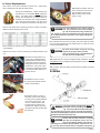
Fig 7A-1. Flowrator assembly components
Failure to install the proper piston can
lead to poor system performance and
possible compressor damage.
!
WARNING
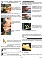
I. Installation
I-1. Disassemble owrator
body using two wrenches and
unscrewing with a counterclock-
wise motion.
7A. Flowrator Coils
1. Ensure suction line connection joints are burr-free and clean.
Failure to do so may increase chances of a leak and introduce con-
taminants to the system. It is recommended to use a pipe cutter to
remove the spun closed end of the suction line.
Do not attempt to touch brazed joints
while hot. Severe burns may result.
!
WARNING
6. Suction Line Connection
2. Swedge (or use a eld supplied coupler) and braze the eld sup-
plied refrigerant suction line tubing to the coil stub using approved
industry practices.
Some Aspen coils may include a Schrader
valve on the suction manifold. Ensure that
the Schrader valve and valve core (where
present) are protected from heat to prevent leakage.
CAUTION
!
The sensing bulb and TXV body MUST be
protected from overheating during braz-
ing. The sensing bulb and TXV body must
be covered using a quench cloth or wet cloth when brazing.
Pointing the brazing ame away from the valve and sensing
bulb provide partial protection only.
!
WARNING
Be aware of the Teon O-ring. Be sure to
replace the O-ring to attain a proper
seal. (The Teon O-ring is located between
the two halves of the owrator)
CAUTION
!
I-2. Replace the Teon O-ring
(located between the halves).
Discard Schrader if present.
O-ring
I-4. Braze the stub-out portion to the liquid line and let cool.
I-3. Slide the attachment nut onto
the liquid line stub out.
I-6. Tighten the nut to a torque of approximately 10-30 ft-lbs. Do NOT
overtighten the nut. Overtightening will impede the piston movement
during operation.
I-5. Taking care that the white
Teon seal is still in place inside
the owrater body, rmly seat the
stub and screw the attachment
nut to owrater body.

4
# 123173
During some installations, a piston change may
be required. If so, the installer MUST change the
piston. Use piston sizes recommended by the
outdoor unit manufacturer. If a sizing chart is not
available, use the piston size chart provided be-
low to size the required piston. The size of the
piston is stamped on the piston body (Fig 7A-2).
II. Piston Replacement
Fig 7A-2
Use the chart below when matching coil with an outdoor unit with a
different nominal capacity than the coil.
Note: Photos are for basic illustration purposes only. Actual equip-
ment conguration may differ from that shown.
II-4. Slide the 13/16” nut over
the lineset and separate the two
halves of the owrator.
Be aware of the Teon O-ring. Be sure to
replace the O-ring to attain a proper
seal. (The Teon O-ring is located between
the two halves of the owrator)
CAUTION
!
Pay close attention to the piston orienta-
tion. The pointed end of the piston MUST
go into the distributor body, towards the
coil. Failure to ensure this orientation will cause the piston
to be bypassed during operation which might damage the
outdoor unit.
CAUTION
!
II-8. Tighten the nut to a torque of approximately 10-30 ft-lbs. Do NOT
overtighten the nut. Overtightening will impede the piston movement
during operation.
II-9. If present, slide the rubber grommet back to position to prevent
air leakage.
II-6. Replace the piston with one
of the correct size. Do not force
the new piston into the body.
Make sure the piston moves
freely in body.
II-1. Evacuate the system as per manufacturer guidelines and rec-
ommendations
II-2. Turn the 13/16” nut once to release any residual pressure in the
coil.
II-3. After ensuring that the coil
is free of any residual pressure,
disassemble the owrator body
completely using two wrenches.
Take great care not to distort the
feeder tubes. The wrench used
to clasp the nut should be turned
in counter-clockwise direction to
unscrew the nut.
II-5. Pull the piston out using a
small wire or pick. Verify the pis-
ton size (size is typically stamped
on the body of the piston - Fig
7A-2). If a different piston size
is required by the outdoor unit
manufacturer, replace the piston
using the small wire provided with
the piston kit.
II-7. Assemble the two halves correctly and ensure that the Teon
O-ring is present between the two halves (See I-5). Slide the 13/16”
nut onto the distributor body.
7B. TXV Coils
Ensure that the TXV selected is compat-
ible with the refrigerant used in the out-
door system (R22 or R410A). TXV caps are
painted green for R22 or pink for R410A. In absence of col-
or, the caps will be marked with the compatible refrigerant.
CAUTION
!
The sensing bulb and TXV body MUST be
protected from overheating during braz-
ing. The sensing bulb and TXV body must
be covered using a quench cloth or wet cloth when brazing.
Pointing the brazing ame away from the valve and sensing
bulb provide partial protection only.
!
WARNING
Fig 7B-1. Components of a typical TXV assembly

5
# 123173
The valves should be sized according to
the capacity of the outdoor unit. Failure to
install the right valve can lead to poor per-
formance and possible compressor damage.
CAUTION
!
Ensure that the TXV bulb is in direct con-
tact with the suction/vapor line. Gap be-
tween the bulb and tube should be avoid-
ed. Failure to do so will impair the proper functioning of the
TXV valve.
CAUTION
!
If the TXV sensing bulb is mounted verti-
cally; the capillary MUST be directed up-
wards. The bulb must be mounted on the
wall opposite to that being directly hit by the refrigerant and
oil leaving the distributor tubes.
CAUTION
!
I. TXV Bulb Horizontal Mounting
II. TXV Bulb Vertical Mounting
The orientation and location of the TXV bulb has a major inuence
on the system performance.
It is recommended that the TXV bulb be installed parallel to the
ground (on a horizontal plane). The bulb position should be at
2 o’clock or 10 o’clock. Fig. 7B-2 shows the recommended position
for the TXV bulb installation in the horizontal plane.
The TXV sensing bulb SHOULD be mounted on the suction line ap-
proximately 6” from the TXV or coil housing using the metal clamp
provided. In order to obtain a good temperature reading and correct
superheat control, the TXV sensing bulb must conform to ALL of the
following criteria:
1. The sensing bulb MUST be in direct and continuous
contact with the suction line.
2. The sensing bulb should be mounted horizontally on
the suction line.
3. The sensing bulb MUST be mounted at the 2 o’clock or
10 o’clock position on the circumference of the suction line.
4. The sensing bulb MUST be insulated from outside air.
A properly mounted sensing bulb will prevent false readings caused
by liquid refrigerant that may have formed inside the suction/vapor
line. Insulation will protect the sensing bulb from false readings due
to contact with warm air.
Fig 7B-3. Recommended location
for vertical TXV bulb mount
As recommended in Section
7B-I, the TXV sensing bulb
should be mounted in a hori-
zontal plane in relation to the
suction/vapor line. However,
some installation congura-
tions may require that the
sensing bulb be mounted ver-
tically. In this instance, place
the bulb opposite the piping
wall being hit by refrigerant
and oil leaving the distributor
tubes, and with capillary tubes
directed upwards as shown in
Fig. 7B-3.
III-1. Inspect the TXV box to conrm that the valve is compatible
with the refrigerant in the system.
Male
(Inlet)
Female
(Outlet)
III-2. Remove the valve from
the box and note the loca-
tion of the inlet side (threaded
male port) and the outlet side
(female swivel nut port).
Note: Photos are for basic illustration purposes only. Actual equip-
ment conguration may differ from that shown.
III. Field-Installed TXV Retrot
When installing an expansion valve, it is not necessary to slide the
coil out of the housing.
For disassembly and piston removal refer to section 7A-I.
III-5. Braze the stub-out portion to the liquid line and let cool.
III-4. Slide the attachment nut onto the liquid line stub out.
(See 7A, I-3)
Fig 7B-2. Recommended location for horizontal TXV bulb mount
Bulb position at
2 o’clock or
10 o’clock

6
# 123173
1. Following outdoor unit manufacturer instructions and recommen-
dations, charge the system with dry nitrogen to a maximum pressure
of 150 PSIG.
3. If any leaks or are discovered, relieve system pressure and repair
leaks. Repeat steps 1-3.
4. With no leaks or weak connections present, evacuate the system
and charge as per the outdoor unit manufacturer instructions and
specications.
Do not attempt to touch brazed joints
while hot. Severe burns may result.
!
WARNING
O-ring
III-6. Remove the additional Tef-
lon O-ring seal from the box and
place on the shoulder just inside
the TXV inlet port. Screw the nut
attached to the stub-out portion of
the owrator body onto the inlet
port of the TXV.
A. Remove the valve stem from
the Schrader port mounted on the
suction line.
B. Screw are nut on TXV equal-
ization tube on to the Schrader
valve stem.
III-7. Tighten all connections taking care to use proper back up.
III-9a. Some Aspen coils come with a Schrader valve on the suction
line. If a Schrader port is present:
III-9b. In some cases, a suction line Schrader port may not be pres-
ent. If a Schrader port is NOT present:
Using a non-bleed expansion valve may re-
quire the use of a hard-start kit. Follow the
outdoor unit manufacturer’s guidelines.
CAUTION
!
When handling or manipulating the equal-
izer tube, take great care not to kink or
make extreme bends in the tubing.
CAUTION
!
III-8. Remove the valve identication sticker from the valve and
place it adjacent to the Aspen model number on unit name plate.
9. Leak Check
2. Check all brazed and screw-
on line connections by applying a
soap solution to the joint. A leak
will produce bubbles in the soap
solution.
A. Install a eld-supplied braze-on Schrader
valve like that shown on the suction line near the
intended sensing bulb mounting location. Follow
valve manufacturer instructions and recommen-
dations for installation.
B. Attach equalizer tube to valve as described in
section III-9a above.
III-10. Mount the sensing bulb as described in section 7B-I or 7B-II.
8. Connecting Refrigerant Lines
1. Release nitrogen holding charge by depressing the Shrader Valve
at the liquid line connection. If no gas releases from the coil, contact
distributor regarding potential leak.
2. Cut off Shrader Valve tting at
the liquid line connection. Use a
tubing cutter for this step. Clean
the burr from the cut tubing to
reduce the chance of future
leaks. Connect the liquid line to
the tubing at the indoor unit.
3. Use a tubing cutter to remove
the spun end from the suction
line connection at the air han-
dler. Clean the burr from the cut
tubing to reduce the chance of
future leaks.
4. To avoid heat damage to grommets where present, remove these
prior to brazing by sliding them over the refrigerant lines and out of
the way.
5. Check to determine if the
evaporator coil has a Shrader
tting on the suction manifold.
If yes, remove the valve core
to prevent heat damage during
brazing. Replace the valve core
once the piping has cooled.
6. Flow nitrogen through the piping when brazing.
7. Braze both refrigerant line connections using proper brazing pro-
cedures.
8. When all line connections are brazed, perform a proper system
evacuation procedure per the outdoor unit manufacturer instructions.
9. Seal the penetration openings where the lineset piping enters the
cabinet.

7
# 123173
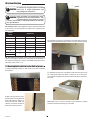
1. Remove shipping brackets on both ends of coil cabinet. Bracket
shown below.
2. Slide coil up to furnace (note:
bottom ange on coil cabinet will
slide under furnace, anges on
furnace should slide inside coil
cabinet) Coil cabinet should be
ush to back side of furnace.
For applications where the coil cabinet is the same height as the fur-
nace use the supplied Z bracket to attach to furnace as shown below.
For applications where the coil cabinet is taller than the furnace use
an L shaped ller bracket to attach to furnace to coil, as shown be-
low.( Bracket is supplied with CB coils with the 8th option code selec-
tion -034)
Note: Make sure to seal all connection joints. Method of sealing
should be performed according to local codes.
2A. Flowrator coils: Add refrigerant until the superheat measured
at the outdoor unit suction/vapor line matches the superheat from
the chart below.
An improperly charged system will likely
cause loss in system performance and
may damage the compressor.
CAUTION
!
Refer to outdoor unit manufacturer charg-
ing guidelines and recommendations. The
recommendations given below are general
in nature and are NOT to supersede outdoor unit manufac-
turer specications.
CAUTION
!
11. Mounting Dedicated Horizontal Coil to Furnace
10. System Charging
Front Side View
Top View of Cabinet
2B. TXV coils: Add refrigerant until the subcooling measured at the
outdoor unit liquid line matches the subcooling recommendation of
the outdoor manufacturer. If chart is unavailable charge the unit to a
subcooling value of 8ºF +/- 1ºF.
Outdoor
Temp
Superheat
°F D.B. Min Nom Max
65 30 35 40
70 26 30 34
75 21 25 29
80 17 20 23
85 12 15 18
90 8 10 12
95
4 5 7
100

8
# 123173
373 Atascocita Rd.
Humble, TX 77396
Phone: 281.441.6500
Toll Free: 800.423.9007
Fax: 281.441.6510
www.aspenmfg.com
# 123173
© Copyright 2017 Aspen Manufacturing. All Rights Reserved
Revised 10/06/2017. Subject to change without notice and without incurring obligation.
-
 1
1
-
 2
2
-
 3
3
-
 4
4
-
 5
5
-
 6
6
-
 7
7
-
 8
8


Aspen Manufacturing CB42E4G210T034 Installation guide
- Type
- Installation guide
- This manual is also suitable for
Ask a question and I''ll find the answer in the document
Finding information in a document is now easier with AI
Related papers
Other documents
-
COMFORT-AIRE MCG24TA2M Installation guide
-
COMFORT-AIRE MCG60P21E Installation, Operation & Maintenance Manual
-
Aspen DA Series Uncased Upflow-Downflow Aluminum Coils Installation guide
-
COMFORT-AIRE HWCG48X0A-CY Operating instructions
-
COMFORT-AIRE HWCG23T0A-CY Operating instructions
-
Carrier CSPHP6012ALA Installation guide
-
Amana CAUFA3626C6 User manual
-
Trane 4PXADU48BS3HAA Installation guide
-
-
Broan HSA1QD Installation guide