Page is loading ...

Low Temperature Incubator
Model
IJ 100
Instruction Manual
- First Edition -
Yamato Scientific Co. LTD.
Thank you for purchasing " Low Temperature
Incubator, IJ100 " of Yamato Scientific Co.,
Ltd.
To use this unit properly, read this "Instruction
Manual" thoroughly before using this unit.
Keep this instruction manual around this unit
for referring at anytime.
WARNING!:
Carefully read and thoroughly understand the
important warning items described in this
manual before using this unit.

Contents
Cautions in Using with Safety...............................................................1
•
Explanation..................................................................................................................1
•
Table of Illustrated Symbols.........................................................................................2
•
Fundamental Matters of “WARNING!” and “CAUTION!”...............................................3
Before Using this unit............................................................................4
•
Requirements for Installation........................................................................................4
•
Change the Direction of Opening/Closing Door............................................................7
Description and Function of Each Part.................................................8
•
Main Unit......................................................................................................................8
•
Control Panel...............................................................................................................9
Operation Method.................................................................................10
•
Sequence of Operation..............................................................................................10
•
Independent overheating prevention device...............................................................12
Handling Precautions ..........................................................................13
Maintenance Method............................................................................16
•
Daily Inspection and Maintenance .............................................................................16
Setting Air Jacket (Optional accessory).............................................17
Long storage and disposal..................................................................18
•
When not using this unit for long term / When disposing............................................18
In the Event of Failure…......................................................................19
•
Safety Device and Error Code....................................................................................19
•
Trouble Shooting........................................................................................................19
After Service and Warranty..................................................................20
Specification.........................................................................................21
Wiring Diagram.....................................................................................22
Replacement Parts Table.....................................................................23
Reference..............................................................................................24
•
List of Dangerous Substances ...................................................................................24

1
Cautions in Using with Safety
Explanation
MEANING OF ILLUSTRATED SYMBOLS
Various symbols are used in this safety manual in order to use the unit without
danger of injury and damage of the unit. A list of problems caused by ignoring
the warnings and improper handling is divided as shown below.Be sure that you
understand the warnings and cautions in this manual before operating the unit.
WARNING!
If the warning is ignored, there is the danger of a problem that
may cause a serious accident or even fatality.
CAUTION!
If the caution is ignored, there is the danger of a problem that may
cause injury/damage to property or the unit itself.
Meaning of Symbols
This symbol indicates items that urge the warning (including the caution).
A detailed warning message is shown adjacent to the symbol.
This symbol indicates items that are strictly prohibited.
A detailed message is shown adjacent to the symbol with specific actions not to
perform.
This symbol indicates items that should be always performed.
A detailed message with instructions is shown adjacent to the symbol.
Illustrated Symbols

2
Cautions in Using with Safety
Table of Illustrated Symbols
Warning
Warning,
generally
Warning,
high voltage
Warning,
high temperature
Warning,
drive train
Warning,
explosive
Caution
Caution,
generally
Caution,
electrical shock
Caution,
scald
Caution,
no road heating
Caution,
not to drench
Caution,
water only
Caution,
deadly poison
Prohibit
Prohibit,
generally
Prohibit,
inflammable
Prohibit,
to disassemble
Prohibit,
to touch
Compulsion
Compulsion,
generally
Compulsion,
connect to the
grounding
terminal
Compulsion,
install on a flat
surface
Compulsion,
disconnect the
power plug
Compulsion,
periodical
inspection

3
Cautions in Using with Safety
Fundamental Matters of “WARNING!” and “CAUTION!”
WARNING!
Do not use this unit in an area where there is flammable or explosive gas
Never use this unit in an area where there is flammable or explosive gas.
This unit is not explosion-proof. An arc may be generated when the power switch is turned on or off,
and fire/explosion may result. (Refer to page24 “List of Dangerous Substances”.)
Always ground this unit
Always ground this unit on the power equipment side in order to avoid electrical shock due to a power
surge.
If a problem occurs
If smoke or strange odor should come out of this unit for some reason, turn off the power key right
away, and then turn off the circuit breaker and the main power. Immediately contact a service
technician for inspection. If this procedure is not followed, fire or electrical shock may result. Never
perform repair work yourself, since it is dangerous and not recommended.
Do not use the power cord if it is bundled or tangled
Do not use the power cord if it is bundled or tangled. If it is used in this manner, it can overheat and
fire may be caused.
Do not process, bend, wring, or stretch the power cord forcibly
Do not process, bend, wring, or stretch the power cord forcibly. Fire or electrical shock may result.
Substances that can not be used
Never use explosive substances, flammable substances and substances that include explosive or
flammable ingredients in this unit. Explosion or fire may occur.
Do not disassemble or modify this unit
Do not disassemble or modify this unit. Fire or electrical shock or failure may be caused.
CAUTION!
During a thunder storm
During a thunderstorm, turn off the power key immediately, then turn off the circuit breaker and the main
power. If this procedure is not followed, fire or electrical shock may be caused.

4
Before Using this unit
Requirements for Installation
WARNING!
1. Always ground this unit
• Connect the power plug to a receptacle with grounding connectors.
• Do not forget to ground this unit, to protect you and the unit from electrical shock in case of
power surge. Choose a receptacle with grounding connectors as often as possible.
• Do not connect the grounding wire to a gas pipe, or by means of a lightning rod or telephone
line. A fire or electrical shock will occur.
2. Choose a proper place for installation
• Do not install this unit in a place where:
♦ Rough or dirty surface.
♦ Flammable gas or corrosive gas is generated.
♦ Ambient temperature exceeds 35°C.
♦ Ambient temperature fluctuates violently.
♦ There is direct sunlight.
♦ There is excessive humidity and dust.
♦ There is a constant vibration.
• Install this unit on a stable place with the space as shown below. Furthermore, make a space
30cm or more above this unit.
Main Unit
More than
15cm
More than
15cm
More than 15cm
Front side
3. Do not use this unit in an area where there is flammable or explosive gas
• Never use this unit in an area
where there is flammable or
explosive gas. This unit is not
explosion-proof. An arc may
be generated when the power
switch is turned ON or OFF,
and fire/explosion may result.
(To know about flammable or
explosive gas, refer to
page24 “List of Dangerous
Substances”.)

5
Before Using this unit
Requirements for Installation
4. Do not modify
• Modification of this unit is strictly prohibited.
This could cause a failure.
5. Installation on horizontal surface
• Set this unit to the flattest place. Setting this
unit on rough or slope place could cause the
vibration or noise, or cause the unexpectible
trouble or malfunction.
CAUTION!
6. Choose a correct power distribution board or receptacle
• Choose a correct power distribution board or receptacle that meets the unit’s rated electric
capacity.
Electric capacity: 100V AC 3.5A
NOTE)
There could be the case that the unit does not run even after turning ON the power. Inspect
whether the voltage of the main power is lowered than the specified value, or whether other
device(s) uses the same power line of this unit. If the phenomena might be found, change the
power line of this unit to the other power line.

6
Before Using this unit
Requirements for Installation
CAUTION!
7. Before/after installing
• It may cause injure to a person if this unit falls down or moves by the earthquake and the
impact. etc..To prevent, take measures that the unit cannot fall down, and not install to busy
place.
8. Handling of power code
• Do not entangle the power cord. This will cause overheating and possibly a fire.
• Do not bend or twist the power cord, or apply excessive tension to it. This may cause a fire
and electrical shock.
• Do not lay the power cord under a desk or chair, and do not allow it to be pinched in order to
prevent it from being damaged and to avoid a fire or electrical shock.
• Keep the power cord away from any heating equipment such as a room heater. The cord's
insulation may melt and cause a fire or electrical shock.
• If the power cord becomes damaged (wiring exposed, breakage, etc.), immediately turn off the
power at the rear of this unit and shut off the main supply power. Then contact your nearest
dealer for replacement of the power cord. Leaving it may cause a fire or electrical shock.
• Connect the power plug to the outlet which is supplied appropriate power and voltage.
9. Draining of condensation
• When the cooling device is operated, condensation may occur on the cooling surface. The
condensation is led out via the drain provided at the bottom on the rear the unit. Therefore,
be sure to set the attached drain-receiving pan.
10. Setting shelf
• Fix the two shelves (attached accessory) on the appropriate position.

7
Before Using this unit
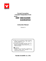
Change the Direction of Opening/Closing Door
This unit can be changed the direction of opening/closing the door easily.
The door opened/closed to the right or left can be selected according to the place where it is
installed and the convenience of operation.
The direction of opening/closing the door is set to left at the shipping from factory. If the
door should be opened/closed to the right, the direction of opening/closing the door can be
changed by the following procedure:
1. Lay down the main body backward in a way that the door unit may come above.
2. By using phillips screwdriver, remove the hinge mounting screws fixing the door in the lower
part of the main body.
3. Pull off the door downward carefully.
4. Pull off the guide pin fixing the upper part of the door, and insert it into the screw hole on the
opposite side (right side).
5. Turn the door 180 degrees, and insert it into the upper guide pin.
6. After adjusting the door position, fix the hinge in the lower part of the door.
7. Replace the main body to complete the procedure.
ヒータ
設定温度
セット
Lowtemp incubator
IJ100
1. Lay down the main body.
4. Remove the guide pin, and
move it to the right side.
2. Remove the lower hinge
and move it to the righ
t
side.
5. Turn around the door
3. Pull out the door.
6. Fix the lower hinge.

8
Description and Function of Each Part
Main Unit
Front view
Power cord
Control panel
Independent overheating
prevention device
Door handle
Specification plate
(Manufacture number)
Power switch
(Earth leakage breaker)
Plate for drainage
Exhaust of cooling fan
Cooling air inhalation
Cooling air inhalation
Rear view

9
Description and Function of Each Part
Control Panel
Main Indicator:
Mainly displays measured temperature.
Heater Lamp:
Lights up when electric power is supplied to the heater.
Trouble Indicator:
Blank in normal operation. Lights up when the device has a
trouble.
(Up/Down) Key
Use these keys when you change the parameters.
Enter Key
Use this key when you decide a modified parameter.

10
Operation Method
Sequence of Operation
Fixed Temperature Operation
1. Turn on the power.
• The main indicator shows the current internal temperature.
MEASURED TEMP
• Fixed temperature operation is started with the target of the
previously set temperature.
When the power is turned on, the controller resets automatically
to the condition immediately before the previous power-off.
Changing Temperature Setting
1. Press the Enter key.
ENTER
• The main indicator blinks the currently set temperature.
MEASURED TEMP
2. Press the key or
key until the required
value is given in the
blinking number
3. When the temperature
reaches to the required
value, press the Enter
key.
ENTER
• The blinking indicator of the temperature setting is turned on,
and the fixed temperature operation is started toward the
newly set temperature.

11
Operation Method
Sequence of Operation
Temperature Preset Function Using Method
• Temperature. Preset is the function to memorize a specified temperature. It is useful to
register any temperature used frequently during operation.
• The preset temperature can be registered any time if the power switch is ON in normal
operation. To register this, follow the procedure shown below.
• Operation continues even when the temperature preset is being registered.
1. Press the Enter key
twice.
ENTER
• The main indicator shows the temperature registered
currently.
• Then, the dot point to the left of the main indicator blinks and
indicates that the operation is in the preset temperature
registration mode.
MEASURED TEMP
NOTE) If not registered, the main indicator blinks .
Temperature Setting Method
1. Press the key or
key until the required
value is given in the
main indicator.
2. When the required value
is given, press the
Enter key.
ENTER
• The previous temperature is deleted.
• Blinking of the previously set temperature is changed to the
display for the current measurement.
Preset Temperature
Re
g
istration Mode

12
Operation Method
Independent overheating prevention device
For the safety device to prevent any over-temperature, an independent overheating prevention device
consisted of the circuits and sensors other than those for the controller is provided in addition to the
controller's automatic function (auto reset) to prevent over-temperature, thus configuring a double safety
measure.
Range of Set Temperature & Functions
This unit has two functions for preventing over-temperature; one is in the controller, and set
to automatically operate at the temperature set in the temperature regulator plus 6 when
delivered from the factory; the other is the temperature regulating dial provided in the upper
right part of this unit, which is used to set the activating temperature for over-temperature
prevention. Such a temperature setting completes a duplex function to prevent
over-temperature.
The independent overheating prevention device provided in the upper right part of this unit
sets temperatures in the range 0 -120 .
If the independent overheating prevention device is activated, the heater circuit is cut off,
and Er03 starts to blink.
If the independent overheating prevention device trips, the status is maintained until the
power is reset, while Er03 is not disabled.
If any wrong value is set for the activating temperature for over-temperature prevention,
units could fail to start, or the independent overheating prevention device could trip even
while the internal temperature is rising, or unexpected accidents including fire could be
occurred.
Using Method
Normally set this to a temperature about 10 (about 2 units in dial) higher than the
temperature set for the controller.
For the independent overheating prevention device to start at the required temperature, first
establish a stable operation at such a required temperature, and lower gradually the setting
dial of the independent overheating prevention device, and then check if the operation is
maintained with stable at the required temperature. Also set the bath temperature. To a
level higher than the temperature activating the independent overheating prevention device,
and check if the independent overheating prevention device trips at the required
temperature.
Caution
When cleaning the independent overheating prevention device or area around it, any touch
on the over-temperature prevention setting dial could change the set temperature.
Therefore, be sure to check if appropriate value is set for the temperature before starting
operation.

13
Handling Precautions
WARNING!
If a problem occurs
If smoke or strange odor should come out of this unit for some reason, turn off the power key
right away, and then turn off the circuit breaker and the main power. Immediately contact a
service technician for inspection. If this procedure is not followed, fire or electrical shock may
result. Never perform repair work yourself, since it is dangerous and not recommended.
Substances that cannot be used
Never use explosive substances, flammable substances and substances that include explosive
or flammable ingredients in this unit. Explosion or fire may occur. (Refer to page24 “List of
Dangerous Substances”.)
When the setting temperature is 35°C or less
When the setting temperature is 35°C or less, pay attention to dryness of sample. The cooling
device of this unit is operated by peltier element. It is set to operate when the setting temperature
is 35°C or less. If container for sample is open, sample may dry.
Condensation drainage
The cooling device may have condensation
during operation. It is drained through the port
on the base to the plate. Check the plate
sometime to avoid overflow.
CAUTION!
Do not step on this unit
Do not step on this unit. It will cause injury if this unit fall down or break.
Do not put anything on this unit
Do not put anything on this unit. It will cause injury if fall.
During a thunder storm
During a thunderstorm, turn off the power key immediately, then turn off the circuit breaker and
the main power. If this procedure is not followed, fire or electrical shock may be caused.
When you open and close the door
When you open and close the door, be careful not to be hit your hands or face. It may cause
injury.

14
Handling Precautions
CAUTION!
Do not use corrosive sample
Stainless steel SUS304 is used for the main hot-air path. However, it may be corroded by strong
acid etc.. Care must be taken, vinyl chloride rubber may be corroded by some kind of solvent, ex
alkaline, oil, halogen etc.
Setting sample
•
••
•
Do not put sample more than 5kg on the shelf provided. When you use some samples, keep
space between each of them.
• Temperature control may lose accuracy if many samples are set. Set sample making room
more than 30% of the shelf in order to keep accuracy of temperature.
It can be cooled to 0°C(minimum)by the product when the room temperature is 20°C and there
is no load. The lowest temperature may change by quantity of sample.
Use under proper temperature range
Operational temperature range of this unit is 0 to 60 . Never set the temperature out of that.
Do not put sample on the internal base
If sample is put directly on the base, device performance will be disturbed. Furthermore, internal
temperature will abnormally rise and it will cause trouble. Never put sample on the base. Fix the
shelf on the metal fittings then set sample on it.

15
Handling Precautions
CAUTION!
Recovery of power failure
When power is supplied after a power failure, the device automatically starts operation again with
the same state as just before the power failure. It is danger that the device starts unattached
operation after a power failure. We recommend for you to turn off the switch of this unit if a
power failure occurs during operation.
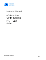
Do not pile up the units
Do not pile up the units like the figure.
This unit is not designed for that using.
ヒー タ
設定 温度
セット
Lowtemp incubator
IJ100
ヒータ
設定温度
セット
Lowtemp incubator
IJ100
Do not put things on the top.
Don't put things on the top like a figure.
Cooling ability declines, and proper
control can't be done any more.
IJ100
After installing
It may cause injure to a person if this unit falls down or moves by the earthquake and the impact.
etc.. To prevent, take measures that the unit cannot fall down.

16
Maintenance Method
Daily Inspection and Maintenance
WARNING!
• Disconnect the power cable from the power source when doing an inspection or maintenance
unless needed.
• Perform the daily inspection and maintenance after returning the temperature of this unit to the
normal one.
• Do not disassemble this unit.
CAUTION!
Main unit maintenance
• Use a well-drained soft cloth to wipe dirt on this
unit. Do not use benzene, thinner or cleanser for
wiping. Do not scrub this unit. Deformation,
deterioration or color change may result in.
Monthly maintenance
• Check the earth leakage breaker function.
1. Connect the power cord.
2. Turn the breaker on.
3. Push the red test switch by a ballpoint pen etc.
4. If there is no problem, the earth leakage breaker will be turned off.
Cleaning of Heat radiate fin
• Clogging radiate fin causes its performance decreased and also
breakdown.
• Keep periodical cleaning depends on how the operating
environment or time is.
1.Lose 4 of upper shelf board screws and take the shelf off.
2.Take off the fan lead wire and 4 of fan screws.
3.Clean the surface of radiate fin with vacuum cleaner after take off
the fin.
Fix them as it was following 3 to 1 order.
PRECAUTIONS: Pay attention not to crush the fin during cleaning.
For any questions, contact the dealer who you purchased this unit from, or the nearest sales
division in our company.
Heat radiate fin
Fin stop screw

17
Setting Air Jacket (Optional accessory)
1. Set the shelf at the lowest stage in a way that the side with margin may come innermost.
2. Set this on the shelf of the air jacket, and push it in.
3. Pus the air jacket inward until it hits the depth.
Set the shelf on the
lowest stage.
Enter this while adjusting i
t
closely to the edge of the
inner bath.

18
Long storage and disposal
When not using this unit for long term / When disposing
CAUTION!
When not using this unit for long term…
• Turn off the power and disconnect the power cord.
WARNING!
When disposing…
• Keep out of reach of children.
• Treat as large trash.
Environmental protection should be considered
We request you to disassemble this unit as possible and recycle the reusable parts considering to
the environmental protection. The feature components of this unit and materials used are
listed below.
Component Name Material
Main Components of Exterior
Casing Steel plate, melamine resin baking finish
Interior Stainless steel plate SUS 304
Air jacket (optional accessory) Aluminum, Neoprene rubber packing
Production plates PET resin film
Main Components of Cooling System
Heat absorb fin Aluminum
Heat radiate fin Copper, Lead solder
Heat radiate cover Steel plate, melamine resin baking finish
Parts attaching plate Steel plate, melamine resin baking finish
Main Components of Electric System
Heater Mica heater, Aluminum, Grass coating wire
Fan Aluminum, Copper wire and other composites
Circuit boards Composites of board, condenser, resistor, transformer, etc.
Power cord, Wiring material, etc. Wiring material of synthetic rubber coating and resin coating
/