Page is loading ...

AirC Control System
Operation instructions
M-AirCM-B1905
ENGLISH

Copyright © 2019 Munters Europe AB
Original instructions

Table of Contents
1. Introduction ....................................................................................................................... 5
1.1. Copyright ................................................................................................................ 5
1.2. About this manual ................................................................................................... 5
2. Control system ................................................................................................................... 6
2.1. General .................................................................................................................. 6
2.2. Humidity control alternatives .................................................................................... 6
2.2.1. Humidity setpoint .......................................................................................... 6
2.2.2. External setpoint .......................................................................................... 6
2.3. Loop controllers ...................................................................................................... 7
2.4. Sensors .................................................................................................................. 8
2.5. Variable frequency drive .......................................................................................... 8
3. User interface .................................................................................................................... 9
3.1. General .................................................................................................................. 9
3.1.1. Start/stop from control system panel .............................................................. 9
3.1.2. Start Page .................................................................................................... 9
3.1.3. Login ......................................................................................................... 10
3.1.4. Main Index ................................................................................................. 10
3.2. Status ................................................................................................................... 11
3.3. Humidity ............................................................................................................... 12
3.3.1. Humidity controller ...................................................................................... 13
3.4. Alarming ............................................................................................................... 14
3.4.1. Alarm types ................................................................................................ 14
3.4.2. Alarm reset ................................................................................................ 14
3.4.3. Alarm menu ............................................................................................... 14
3.4.4. Alarm settings ............................................................................................ 15
3.4.5. Humidity deviation ...................................................................................... 15
3.4.6. Temperature deviation ................................................................................ 15
3.5. Settings ................................................................................................................ 16
3.5.1. Operating mode ......................................................................................... 16
3.5.2. Sensors ..................................................................................................... 17
3.5.3. Remote ...................................................................................................... 17
3.5.4. Communication .......................................................................................... 18
3.5.5. Service ...................................................................................................... 18
3.5.6. HMI settings ............................................................................................... 18
3.5.7. Version ...................................................................................................... 18
3.5.8. Time & Date ............................................................................................... 18
4. Fault tracing ..................................................................................................................... 19
AirC Control System
3


1. Introduction
1.1. Copyright
The contents of this manual can be changed without prior notice.
NOTE
This manual contains information which is protected by copyright laws. It is not allowed
to reproduce or transmit any part of this manual without written consent from Munters.
Munters Europe AB, P.O. Box 1150, SE-16426 KISTA Sweden
1.2. About this manual
This supplementary manual contains important information and guidelines for the operation of the con-
trol system in the delivered dehumidifier. It must be used together with the User manual for the dehu-
midifier to make a complete documentation.
Details about the dehumidifier is available in the User manual. Do not operate the dehumidifier without
reading also the User manual.
Important user information such as intended use and safety information is also available in the User
manual for the dehumidifier.
NOTE
Some of the options described are not available for all types of dehumidifiers.
AirC Control System
5

2. Control system
2.1. General
This section provides an overview of the setup of the advanced built-in microprocessor control system.
The microprocessor and related components have already been set up at the factory for your particular
application with the exception of the means to communicate the required input to the microprocessor.
On delivery, the control system is preset with standard settings, which can be adjusted on site during
installation and commissioning.
The microprocessor monitors outside ambient conditions and space conditions. It can then automatical-
ly energize dehumidification to maintain desired space conditions.
The unit can optionally be monitored and turned on by a Building Management System (BMS) using a
Modbus communication protocol. The Munters AirC controller has support for Modbus RTU through
2/3-wired RS-485 interface and Modbus TCP/IP through Ethernet.
Optionally, the individual functions can be controlled directly by an outside source. A thermostat/humidi-
stat or a BMS is used to give signals to turn on the unit.
Where this method of control is used, the microprocessor still monitors and protects the internal func-
tions.
The Munters AirC control system consists of the controller, HMI and several sensors. The controller is
powered by a 24 VAC transformer.
There are four different access levels:
• Level 0: Viewing of all operational settings and values.
• Level 1: Operator login.
• Level 2: Service login.
• Level 3: System configuration.
2.2. Humidity control alternatives
There are two possibilities for humidity control. The selected option is set up when the unit is config-
ured.
2.2.1. Humidity setpoint
The unit is controlled by an internal, adjustable setpoint which can be in one of three different formats:
• percent relative humidity (%RH)
• calculated dew point (temperature)
• calculated absolute humidity (g/kg)
The setpoint can be set from the HMI, through Modbus communication or by an external analog input.
The analog input can be configured as 0-20 mA, 4-20 mA or 0-10 V.
2.2.2. External setpoint
The reactivation heater is directly controlled by an external analog signal, 0-20 mA, 4-20 mA or 0-10 V.
In this way, the dehumidification capacity of the unit is controlled between 0 and 100 %. The incoming
signal is converted to a setpoint for heater control.
AirC Control System
6

2.3. Loop controllers
The control system loop controllers work to maintain setpoints for humidity and the reactivation temper-
ature.
Hysteresis limits can be set for humidity to allow variation around the setpoint value within specified val-
ues before the unit is turned on or off.
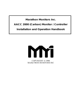
In the figure below, the indicated values refer to:
%RH Relative humidity
SP Setpoint
H+ Hysteresis upper limit
H- Hysteresis lower limit
Figure 1. Hysteresis
%RH
SP
H+
H-
If the humidity exceeds the hysteresis upper limit (Hyst Start), the dehumidifier will start and begin to
regulate to the setpoint.
The regulation will continue as long as the humidity value is above the hysteresis lower limit (Hyst
Stop). The dehumidifier will stop only when the humidity value falls below the hysteresis lower limit.
It will start again the next time the value exceeds the upper limit.
AirC Control System
7

2.4. Sensors
The following are examples of sensors that can be used to give information input to the controller.
• Reactivation temperature
• Wet air temperature
• Return or room temperature
• Return or room humidity
• Rotor rotation
• Reactivation filter pressure switch
• Process filter pressure switch
2.5. Variable frequency drive
Variable frequency drives (VFD) are used to control electric motor speed. They replace the motor con-
tactors and overload relays and provide a soft start for the motor. If the VFD detects a problem such as
high amperage, low voltage etc. it shuts the motor down to protect it and indicates a fault condition.
AirC Control System
8

3. User interface
3.1. General
3.1.1. Start/stop from control system panel
Press the start/stop button in the upper right corner to operate the unit.
• From Off, press once to go to Automatic mode, with sensor control.
• From Off or Automatic, press and hold for more than 3 seconds to go to Manual mode, 100% capaci-
ty dehumidification.
• From Automatic or Manual, press once to go to Off.
3.1.2. Start Page
The start page displays the following information:
• Humidity
• Temperature
• Reactivation temperature
• Operation mode
• Unit status
• Alarm status, alarms and informations
Press
or to go to Main Index.
AirC Control System
9

3.1.3. Login
User login password is 1111.
Password enter
Press
and to select the position.
Press
and to change the digit.
Press to confirm the correct PIN-code.
Press to go to the Start page.
3.1.4. Main Index
Select the icon for the desired menu and press .
NOTE
See the unit specific Report document for default settings.
AirC Control System
10

3.2. Status
Select the icon and press .
No login is required.
NOTE
Menu contents can vary depending on configuration.
Item Values Unit
Operating mode Start Up Delay*Alarm*Off*Automatic*Manual
Unit status Off*Off-Alarm*Waiting*Standby*Starting*Run-
ning*Stopping
Operating type Sensor*Full capacity*External heater control
Remote start On*Off
Relative humidity 0.0... 100.0 %RH
Dewpoint -60.0... +60.0 °C
Absolute humidity 0.0... 20.0 g/kg
Humidity setpoint 0.0... 100.0 %RH
Dewpoint setpoint -60.0... +60.0 °C
Floating setpoint Sensor value + offset °C
Humidity setpoint 0.0... 20.0 g/kg
Humidity setpoint (re-
mote)
0.0... 100.0 %RH
Dewpoint setpoint (re-
mote)
-60.0... +60.0 °C
Humidity setpoint (re-
mote)
0.0... 20.0 g/kg
Temperature -64.0... 200.0 °C
React temperature -64.0... 200.0 °C
Wet air temperature -64.0... 200.0 °C
Surface temperature -64.0... 200.0 °C
AirC Control System
11

Item Values Unit
Ext heater signal 0.0... 100.0 %
Calculated heater set-
point
0... 150 °C
React max tempera-
ture
-64.0... 200.0 °C
Heater output 0... 100 %
React fan On*Off
Process fan On*Off
Rotor On*Off
Time left for service 0... 32000 Hours
Time left for service 0... 1000 Days
Log out
3.3. Humidity
Select the icon and press .
User password or higher is required.
NOTE
Menu contents can vary depending on configuration.
Item Values Unit
Relative humidity 0.0... 100.0 %RH
Dewpoint -60.0... +60.0 °C
Absolute humidity 0.0... 20.0 g/kg
Humidity setpoint 0.0... 100.0 %RH
Dewpoint setpoint -60... +60 °C
Humidity setpoint 0.0... 20.0 g/kg
AirC Control System
12

Item Values Unit
Humidity setpoint (re-
mote)
0.0... 100.0 %RH
Dewpoint setpoint (re-
mote)
-60... +60 °C
Humidity setpoint (re-
mote)
0.0... 20.0 g/kg
Surface temperature -64.0... 200.0 °C
Floating setpoint Sensor value + offset °C
Floating setpoint off-
set
-10.0... +10.0 °C
Humidity hysteresis
start
-10.0... +10.0 %RH
Humidity hysteresis
stop
-10.0... +10.0 %RH
Dewpoint hysteresis
start
-10.0... +10.0 °C
Dewpoint hysteresis
stop
-10.0... +10.0 °C
Humidity hysteresis
start
-10.0... +10.0 g/kg
Humidity hysteresis
stop
-10.0... +10.0 g/kg
Remote start Off*On
Ext. heater signal 0.0... 100.0 %
Start limit 0.0... 100.0 %
Relative humidity 0.0... 100.0 %RH
Force limit start 0... 100 %RH
Force limit hyst. -10.0... 0.0 %RH
Humidity controller >
Operating type Sensor*Full capacity*External heater control
Log out
3.3.1. Humidity controller
Item Values Unit
Controller output 0... 100 %
Humidity P-factor 0.00... 20.00
Humidity I-time 0... 3600 sec
Humidity D-time 0... 3600 sec
Humidity sample rate 1... 60 sec
Humidity startup value 0... 100 %
AirC Control System
13

3.4. Alarming
3.4.1. Alarm types
The control system can give two different types of notifications:
• Alarm - stops the whole unit. Needs to be manually reset.
• Information - warning or indication of service need.
3.4.2. Alarm reset
Access the alarming menu with the HMI buttons.
Alarm list is showing all active alarms.
Reset all active alarms after correction: Select Acknowledge All Alarms > Yes and press ENTER.
User or higher login is required.
3.4.3. Alarm menu
Select the icon and press
.
No login is required.
Select list of active alarms or alarm history list, latest alarm first.
Acknowledge all alarms and Alarm settings require User or higher login.
Select Acknowledge to reset active alarms after correction.
AirC Control System
14

3.4.4. Alarm settings
NOTE
Menu contents can vary depending on configuration.
Item Values Unit
Humidity deviation >
Temperature deviation >
React filter clogged, delay 0... 3600 sec
Process filter clogged, delay 0... 3600 sec
Sensor fault react temp, delay 0... 300 sec
Sensor fault wet air temp, delay 0... 300 sec
Sensor fault surface temp, delay 0... 300 sec
Sensor fault humidity sensor 1, delay 0... 300 sec
Sensor fault humidity sensor 2, delay 0... 300 sec
Sensor fault temp sensor 1, delay 0... 300 sec
Sensor fault temp sensor 2, delay 0... 300 sec
Process fan fault, delay 0... 60 sec
React fan fault, delay 0... 60 sec
Rotor fault, delay 0... 60 sec
Rotor stopped, delay 0... 3600 sec
Heater fault, delay 0... 60 sec
Long cooling time, delay 0... 3600 sec
Clear alarm history Cancel*Reset
Log out
3.4.5. Humidity deviation
Item Values Unit
Humidity deviation type Disabled*High limit*Low
limit*Both
Delay 0... 300 min
High limit 0.0... 100.0 %RH
Low limit -100.0... 0.0 %RH
3.4.6. Temperature deviation
Item Values Unit
Temperature deviation type Disabled*High limit*Low
limit*Both
Delay 0... 300 min
High limit -100.0... 100.0 °C
Low limit -100.0... 100.0 °C
AirC Control System
15

3.5. Settings
Select the icon and press .
NOTE
Menu contents can vary depending on configuration.
Operating mode >
Sensors >
Remote >
Communication >
Service >
HMI settings >
Version >
Time & Date >
3.5.1. Operating mode
Fan mode >
Timer >
Fan mode
Item Values Unit
Process fan mode On demand*Continuous*Intermit
Intermit interval 1... 120 min
Intermit run time 1... 30 min
AirC Control System
16

Timer
Item Values Unit
Timer Disabled*Enabled
Timer status Off*On
Start time 00:00 hh:mm
Stop time 00:00 hh:mm
3.5.2. Sensors
Item Values Unit
Operating type Sensor*Full capacity*External heater control
Control type Relative*Dewpoint calc*Absolute calc
Humidity sensor 1
type
Disabled*0-10V*0-20mA*4-20mA*Modbus
Humidity sensor 1 min 0... 100 %RH
Humidity sensor 1
max
0... 100 %RH
Humidity sensor 2
type
Disabled*0-10V*0-20mA*4-20mA*Modbus
Humidity sensor 2 min 0... 100 %RH
Humidity sensor 2
max
0... 100 %RH
Control sensor Sensor 1*Sensor 2*Average*Minimum*Maxi-
mum
Temp sensor 1 type Disabled*0-10V*0-20mA*4-20mA*Modbus
Temp sensor 1 min -80... 200 °C
Temp sensor 1 max -80... 200 °C
Temp sensor 2 type Disabled*0-10V*0-20mA*4-20mA*Modbus
Temp sensor 2 min -80... 200 °C
Temp sensor 2 max -80... 200 °C
Temp control sensor Sensor 1*Sensor 2*Average*Minimum*Maxi-
mum
Restart
3.5.3. Remote
Item Values Unit
External start Disabled*Enabled
Humidity control type Sensor*Full capacity*External heater control
External heater con-
trol type
Disabled*0-10V*0-20mA*4-20mA
Remote setpoint type Disabled*0-10V*0-20mA*4-20mA
Remote setpoint min -100... 100 %RH /
°C / g/kg
Remote setpoint max -100... 100 %RH /
°C / g/kg
Restart
AirC Control System
17

3.5.4. Communication
TCP/IP
Item Values Unit
IP address
Netmask
Gateway
Use DHCP Active*Passive
Restart
Modbus
Item Values Unit
Slave ID 1... 247
Baud rate 9600*19200*38400
Data + Stop bits 8+1*8+2
Parity None*Even*Odd
Termination Active*Passive
Restart
3.5.5. Service
Only for service engineers.
Corresponding login required.
3.5.6. HMI settings
Item Values Unit
Start view Simple*Advanced
Screen saver Yes*No
Screen saver delay 1... 60 min
Auto logout delay 1... 60 min
3.5.7. Version
Item
Unit type
Fabrication number
Software version
3.5.8. Time & Date
Item
Set date
Set time
AirC Control System
18

4. Fault tracing
NOTE
Other alarm indications are possible. Consult Munters service in these cases.
Fault symptom Indication Possible cause Corrective action
The unit has
stopped.
The display win-
dow is not lit.
Power supply failure. Check the supply to the unit.
A fuse and/or circuit breaker
has tripped.
Investigate the cause of the
fault and rectify. Reset the
fuse and circuit breaker.
If the fault re-occurs, contact
Munters service.
The unit is in AU-
TO mode and
has stopped.
The display win-
dow is lit.
Dehumidification is not re-
quired.
Operation mode is STAND-
BY
Make sure that the current
humidity level is lower than
the setpoint.
Set the setpoint lower than
the actual humidity value and
see if the unit starts.
Make sure that the the hu-
midity sensor value is cor-
rect.
Remote start not connected.
Operation mode is WAITING.
Make sure that the wiring for
the remote start function is
correct.
Make sure that the input is
bridged.
The unit has
stopped.
The red alarm
lamp on the con-
trol panel is blink-
ing.
The following text
is shown on the
display:
Process fan fault Low power supply Check flows, fan motor and
circuit breaker.
Remedy any faults, reset the
circuit breaker.
React fan fault
Rotor fault Drive motor overheating; ro-
tor runs with difficulty.
Check the motor, drive and
the rotor seals. Reset the cir-
cuit breaker.
Rotor stopped Drive belt error. Check the tension and condi-
tion of the drive belt. Check
the rotor rotation sensor.
AirC Control System
19

Fault symptom Indication Possible cause Corrective action
Heater fault The air flow is too low. One
of the high temperature cut-
outs has tripped, either due
to an obstruction in the reac-
tivation airflow or because
the reactivation airflow has
been set too low.
Make sure that the airflow is
correct, see the User manual
for the unit.
Reset the motor circuit
breaker.
Reactivation heater error. Reset the fuse and circuit
breaker. If the fault re-occurs,
contact Munters service.
Sensor fault Re-
act Temperature
Temperature is out of the
sensor limits.
Investigate the sensor func-
tion.
Sensor fault Wet
Air Temperature
Sensor fault Sur-
face Temperature
Sensor fault Tem-
perature Sensor
Sensor fault Hu-
midity Sensor
Humidity is out of the sensor
limits.
Yellow informa-
tion symbol on
the screen.
The following text
is shown on the
display:
React filter clog-
ged
Inlet filter is clogged Inspect and replace filter if
necessary
Process filter
clogged
Time for service Service interval counter has
reached the preset service
time.
Contact Munters to book a
service visit.
Sensor Fault Hu-
midity Sensor 1
Relative humidity sensor 1 is
out of the sensor limits
Investigate the sensor func-
tion.
Sensor Fault Hu-
midity Sensor 2
Relative humidity sensor 2 is
out of the sensor limits
Sensor Fault
Temperature 1
Temperature sensor 1 is out
of the sensor limits
Sensor Fault
Temperature 2
Temperature sensor 2 is out
of the sensor limits
Too long cooling
time
The cooling temperature isn't
reached within set time
Check the air flow and the
heater.
Humidity devia-
tion
Humidity measurement devi-
ates from the humidity set-
point more than the preset
limits
Reset the alarm.
Temperature de-
viation
Temperature measurement is
not between the preset limits
The unit is run-
ning but is not re-
ducing the humid-
ity.
Humidity devia-
tion
Reactivation and process air-
flows do not correspond to
the rated airflows.
Measure and adjust the reac-
tivation and process airflows,
see the User manual for the
unit.
AirC Control System
20
/